Nanosecond colloidal quantum dot lasers
for sensing
B. Guilhabert,1∗C. Foucher,1A-M. Haughey,1E. Mutlugun,2,3,4Y. Gao,2J. Herrnsdorf,1H.D. Sun,5H.V. Demir,2,3M.D. Dawson1and N.
Laurand1
1Institute of Photonics, University of Strathclyde, Glasgow G4 0NW, UK 2Luminous!, Centre of Excellence for Semiconductor lighting and Displays, School of Electrical and Electronics Engineering, School of Physical and Mathematical Sciences,
Nanyang Technological University, 639798, Singapore
3Department of Electrical and Electronics Engineering, Department of Physics and UNAM -Institute of Material Science and Nanotechnology, Bilkent, Ankara, Turkey 4Electrical-Electronics Engineering, Abdullah Gul University, Kayseri, Turkey 5Division of Physics and Applied Physics, Centre for Disruptive Photonic Technologies (CDPT), School of Physical and Mathematical Sciences, Nanyang Technological University,
637371, Singapore ∗[email protected]
Abstract: Low-threshold, gain switched colloidal quantum dot (CQD) distributed-feedback lasers operating in the nanosecond regime are reported and proposed for sensing applications for the first time to the authors’ knowledge. The lasers are based on a mechanically-flexible polymeric, second order grating structure overcoated with a thin-film of CQD/PMMA composite. The threshold fluence of the resulting lasers is as low as 0.5 mJ/cm2 for a 610 nm emission and the typical linewidth is below 0.3 nm. The emission wavelength of the lasers can be set at the design stage and laser operation between 605 nm and 616 nm, while using the exact same CQD gain material, is shown. In addition, the potential of such CQD lasers for refractive index sensing in solution is demonstrated by immersion in water.
© 2014 Optical Society of America
OCIS codes:(250.5590) Quantum-well, -wire and -dot devices; (140.3490) Lasers, distributed-feedback; (280.4788) Optical sensing and sensors.
References and links
1. Q. Sun, Y. Wang, L. S. Li, D. Wang, T. Zhu, J. Xu, C. Yang, and Y. Li, “Bright, multicoloured light-emitting diodes based on quantum dots,” Nature Photon. 1, 717–722 (2007).
2. T. H. Kim, K. S. Cho, E. K. Lee, S. J. Lee, J. Chae, J. W. Kim, D. H. Kim, J. Y. Kwon, G. Amaratunga, S. Y. Lee, B. L. Choi, Y. Kuk, J. M. Kim, and K. Kim, “Full-colour quantum dot displays fabricated by transfer printing,” Nature Photon. 5, 176–182 (2011).
3. S. Nizamoglu, G. Zengin, and H. V. Demir, “Color-converting combinations of nanocrystals emitters for warm-white light generation with high color rendering index,” Appl. Phys. Lett. 92, 031102 (2008).
4. S. Chanyawadee, P. G. Lagoudakis, R. T. Harley, M. D. B. Charlton, D. V. Talapin, H. W. Huang, and C. H. Lin, “Increased color-conversion efficiency in hybrid light-emitting diodes utilizing non-radiative energy transfer,” Adv. Mater. 22, 602–606 (2009).
5. V. I. Klimov, A. A. Mikhailovsky, S. Xu, A. Malko, J. A. Hollingsworth, C. A. Leatherdale, H. J. Eisler, and M. G. Bawendi, “Quantization of multiparticle auger rates in semiconductor quantum dots,” Science 287, 1011 (2000).
6. V. Klimov, A. A. Mikhailovsky, S. Xu, A. Malko, J. A. Hollingsworth, C. A. Leatherdale, H. J. Eisler, and M. G. Bawendi, “Optical gain and stimulated emission of nanocrystal quantum dots,” Science 290, 314 (2000). 7. A. V. Malko, A. A. Mikhailovsky, M. A. Petruska, J. A. Hollingsworth, H. Htoon, M. G. Bawendi, and V. I.
Klimov, “From amplified spontaneous emission to microring lasing using nanocrystal quantum dot solids,” Appl. Phys. Lett. 81, 1303 (2002).
8. S. Hoogland, V. Sukhovatkin, I. Howard, S. Cauchi, L. Levina, and E. H. Sargent, “A solution-processed 1.53µm quantum dot laser with temperature-invariant emission wavelength,” Opt. Express 14, 3273–3281 (2006). 9. J. Schafer, J. P. Mondia, R. Sharma, Z. H. Lu, A. S. Susha, A. L. Rogach, and L. J. Wang, “Quantum dot
microdrop laser,” Nano Lett. 8, 1709–1712 (2008).
10. V. M. Menon, M. Luberto, N. V. Valappil, and S. Chatterjee, “Lasing from InGaP quantum dots in a spin-coated flexible microcavity,” Opt. Express 16, 19535–19540 (2008).
11. C. Dang, J. Lee, C. Breen, J. S. Steckel, S. Coe-Sullivan, and A. Nurmikko, “Red, green and blue lasing enabled by single-exciton gain in colloidal quantum dot films,” Nature Nanotechnology 7, 335–339 (2012).
12. Y. Chen, B. Guilhabert, J. Herrnsdorf, Y. Zhang, A. R. Mackintosh, R. A. Pethrick, E. Gu, N. Laurand, and M. D. Dawson, “Flexible distributed-feedback colloidal quantum dot laser,” Appl. Phys. Lett. 99, 241103 (2011). 13. F. Todescato, I. Fortunati, S. Gardin, E. Garbin, E. Collini, R. Bozio, J. J. Jasieniak, G. D. Giustina, G. Brusatin,
S. Toffanin, and R. Signorini, “Soft-lithographed up-converted distributed feedback visible lasers based on CdSe-CdZnS-ZnS quantum dots,” Adv. Func. Mater. 22, 337–344 (2012).
14. V. C. Sundar, H. J. Eisler, T. deng, Y. Chan, and L. T. amd M G. Bawendi, “Soft-lithographically embossed multilayered distributed feedback nanocrystal lasers,” Adv. Mater. 16, 2137–2141 (2004).
15. A. Rose, Z. Zhu, C. F. Madigan, T. M. Swager, and V. Bulovic, “Sensitivity gains in chemosensing by lasing action in organic polymers,” Nature 434, 876–879 (2005).
16. Y. Yang, G. A. Turnbull, and I. D. W. Samuel, “Sensitive explosive vapor detection with polyfluorene lasers,” Adv. Funct. Mater. 20, 2093–2097 (2010).
17. Y. Tan, C. Ge, A. Chu, M. Lu, W. Goldshlag, C. S. Huang, A. Pokhriyal, S. George, and B. T. Cunningham, “Plastic-based distributed feedback laser biosensors in microplate format,” IEEE Sensors J. 12, 1174–1180 (2012).
18. C. Vannahme, M. C. Leung, F. Richter, C. L. C. Smith, P. G. Hermannsson, and A. Kristensen, “Nanoimprinted distributed feedback lasers comprising TiO2tin films: design and guidelines for high performance sensing,” Laser Photonics Rev. 7, 1–7 (2013).
19. E. Mutlugun, P. L. Hernandez-Martinez, C. Eroglu, Y. Coskun, T. Erdem, V. K. Sharma, E. Unal, S. K. Panda, S. G. Hickey, N. Gaponik, and H. V. A. Eychmller, “Large-are (over 50cm x 50cm) freestanding films of colloidal InP–ZnS quantum dots,” Nano Lett. 12, 3986–3993 (2012).
20. H. Mattoussi, J. M. Mauro, E. R. Goldman, G. P. Anderson, V. C. Sundar, F. V. Mikulec, and M. G. Bawendi, “Self-assembly of CdSe–ZnS quantum dot bioconjugates using an enginneered recombinant protein,” JACS 122, 12142–12150 (2000).
21. D. R. Larson, W. R. Zipfel, R. M. Williams, S. W. Clark, M. P. Bruchez, F. W. Wise, and W. W. Webb, “Water-soluble quantum dots for multiphoton fluorescence imaging in vivo,” Science 300, 1434–1436 (2003). 22. Y. Boucher, A. Deryagin, V. Kuchinskii, and G. Sokolovskii, “Near-threshold spectral and modal characterisitics
of a curved-grating quantum well distributed feedback,” Nanotechnology 14, 615–618 (2003).
23. A. M. Haughey, B. Guilhabert, A. L. Kanibolotsky, P. J. Skabara, G. A. Burley, M. D. Dawson, and N. Laurand, “An organic semiconductor laser based on star-shaped truxene-core oligomers for refractive index sensing,” Sen-sors and Actuators B: Chemical 185, 132–139 (2013).
1. Introduction
Colloidal quantum dots (CQDs) are nanometre-scale light emitters based on inorganic semiconductors, usually capped with organic surfactants to avoid aggregation. They are characterized by high photoluminescence quantum efficiency, broad absorption spectra, narrow emission bandwidths and further benefit from a controllable emission wavelength through size tuning. These characteristics, combined with the compatibility of CQDs with solution-processing techniques, make them a very attractive class of material for the realization of photonic devices including next generation displays [1, 2] and hybrid light-emitting diodes [3, 4]. The use of CQDs as laser materials is also an active field of research and has its origin in the initial demonstration of stimulated emission in a film of neat CdSe/ZnS CQDs 13 years ago [5, 6]. Since then, a number of studies on the dynamics of optical amplification in CQDs as
well as device demonstrations have followed including, among the latter, reports of whispering gallery mode lasers [7, 8, 9], vertical cavity surface emitting lasers [10, 11] and distributed feedback (DFB) lasers [12, 13, 14]. However, except in a limited number of cases such laser demonstrations have used ultrafast (10s of fs to a few ps) optical pulse excitation. While this is appropriate for photophysical studies and acceptable for initial development of the technology, operation with such short pulses has limited applicability because it necessitates the use of bulky and expensive pump lasers. To enable practical implementation of CQD lasers, operation with nanosecond or longer pulse duration is necessary. If low-threshold operation in such a regime can be achieved, it will then be possible to envisage pumping CQD laser systems with compact Q-switched solid-state lasers and possibly, for sufficiently low threshold, with laser diodes. The result will be a reduction in the footprint and cost of the CQD laser technology, bringing it closer to applications.
Herein, we report “hybrid plastic” CdSe/ZnS CQD lasers, i.e. made from an inorganic gain material in combination with a polymer cavity, operating in the nanosecond regime when gain-switched with 5 ns-long pump pulses. One identified barrier to operation in such a temporal regime when using CQDs is the effect of Auger recombination, which basically limits the optical gain lifetime [5]. Circumventing or minimizing this problem necessitates optimization of the gain medium (e.g. using a high-density of CQDs [6]) and/or of the cavity (e.g. with a low-loss optical cavity [9]). In our work, CQD lasers with a few nanosecond-pulse duration are made possible by utilizing a planar distributed feedback cavity that includes a high surface quality thin film made of an optimized CQD-composite. Importantly, the planar thin film architecture of DFB lasers enables low-threshold oscillation thanks to a simple and efficient optical excitation of the gain medium as well as an adequate laser mode confinement. The resulting lasers have, to our knowledge, the lowest threshold for such a pulse duration (as low as 0.5 mJ/cm2, 100 kW /cm2), making them suitable for pumping with compact solid-state lasers. The DFB structure chosen here also enables emission wavelength versatility at the design stage through fine tuning of the cavity parameters: our lasers are shown to operate over a 11-nm spectral window in this way, while using the same CQD gain material. Furthermore, for ease-of-implementation, our DFB lasers are designed for vertical emission and, by way of example for applications, we demonstrate their potential for sensing.
Optically-pumped DFB lasers represent attractive platforms for optical sensing; for example, organic DFB lasers are being researched for “sniffing” explosives [15, 16] and for the specific, high-sensitivity detection of analytes in biological solutions, e.g. biomarkers, with related uses in the biological and medical sciences [17]. A “plastic” sensor device having some amount of flexibility/bendability can be beneficial here, e.g., facilitating integration with existing labware. In addition, this technology offers the potential for high performance sensing within compact or lab-on-chip systems [18]. We foresee that CQDs represent an attractive alternative to dyes and organic semiconductors as a gain material replacement in DFB laser sensing platforms. CQDs are suited for optical-pumping arrangement because photons with energies higher than the bandgap will be absorbed, thereby relaxing tolerances on the pump wavelength. Under comparable fluence, CQDs are also more photostable than organic materials and should lead to more reliable lasers. As stated before, CQDs are compatible with solution-processing and can therefore be incorporated in plastic, flexible devices [19]. Finally, specific and highly sensitive detection requires adequate surface functionalization of the DFB laser. CQD DFB laser sensors will benefit from the available library of surface-functionalization chemistry developed for the current main use of CQDs i.e. fluorescent labels for bio-imaging [20, 21]. Despite all their attractiveness, CQD DFB laser sensors will only be viable if the overall system can be made relatively compact. Once again, this necessitates low threshold CQD lasers operating in the nanosecond or longer pulse regime. This present work represents a first step in that direction.
In the following, the design structure of our DFB lasers is explained and details on sample fabrication as well as a description of the experimental set-ups are given in section 2. Optical characterization of thin films of CQD dispersed in poly(methyl methacrylate)(PMMA), which are used as gain material in our lasers, and their capability to sustain stimulated emission are presented in section 3.1. The experimental demonstration of laser operation under optical pumping in the nanosecond-regime is then reported and discussed in section 3.2. Finally, in section 3.3, proof-of-principle refractive index sensing is demonstrated by immersing lasers in water and monitoring the shift in the emission wavelength. This basic capability demonstration paves the way for further studies of the application of CQD lasers to (bio-) sensing.
2. Device structure, materials and methods 2.1. Laser structure
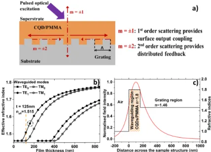
The lasers reported in this paper are based on a DFB cavity. The structure consists of a nano-patterned polymeric substrate overcoated with a thin film of CQD/PMMA composite. The superstrate, i.e., the medium above the gain layer, is either air or water (as explored in section 3.3). The nanostructure on the surface of the substrate is a 1-dimensional second order grating for the desired wavelength of operation (in the 600-620 nm spectral region here). Some of the light generated in the CQD/PMMA thin film upon optical excitation is then guided in the film and interacts with the grating. If the film provides optical gain, then optical feedback generated by the second order of diffraction gives rise to laser oscillation, while the first order of diffraction leads to a vertical emission (i.e., normal direction to the film) of the laser output (Fig. 1(a)). The overall structure is designed so that the laser oscillates in a single transverse mode (TE0). This single mode design has been derived on the basis of the refractive indices of the CQD/PMMA system (n∼1.8) and of the polymeric substrate material (1.46). Figure 1(b) shows the dispersion curve of the first few possible modes, represented as the modal effective refractive index plotted versus the film thickness. The laser wavelength is given by the Bragg wavelength and is for a second order grating:λbragg= ne f f× Λ, where ne f f is the effective refractive index of the propagating mode in the slab waveguide formed by the gain and the grating materials andΛ the periodicity of the grating. The thickness of the film is chosen here to be around 130 and 160 nm for gratings with a 390 and 400 nm periodicity, respectively, in order to match the 611 nm wavelength of maximum gain of the CQD films (see section 3.1). In that range of thickness only the TE0mode can oscillate. This idealized structure can be slightly altered in order to obtain different emission wavelengths. The normalised TE0transverse mode profile is represented in Fig. 1(c) for a structure with a film thickness of 160 nm. Its overlap with the CQD-film (the gain region) is 35%, thereby enabling efficient amplification and hence low-threshold operation.
2.2. Materials and sample preparation
The CQDs used in the following study are based on CdSe as core material surrounded with a ZnS shell. These CQDs were obtained commercially (Lumidots from Sigma-Aldrich Ltd.) initially dispersed in toluene at a concentration of 5 mg/mL. The solution has a photolumines-cence (PL) emission centred at 590 nm as specified by the datasheet with a full width at half the maximum (FWHM) of∼40 nm owing the size distribution of these nanocrystals within the solution. To obtain high-quality thin films, the CQDs were blended with PMMA for an optimum CQD/PMMA weight ratio (w/r) of 50/1.6. Powder of PMMA (molecular weight 120,000), toluene and chloroform were also bought from Sigma-Aldrich Ltd. The solvents were further purified through a 0.2µm PTFE filter to reduce possible contamination from
Fig. 1. a) Schematic of a DFB laser based on a second order grating, b) the effective refrac-tive index of the modes plotted against the thickness of a film of refracrefrac-tive index 1.8. For thicknesses between 130 nm and 160 nm, only the TE0mode can oscillate, c) Normalised
TE0mode profile for a film thickness of 160 nm matching the propagation condition
indi-cated in b) by the circle (ne f f∼1.566).
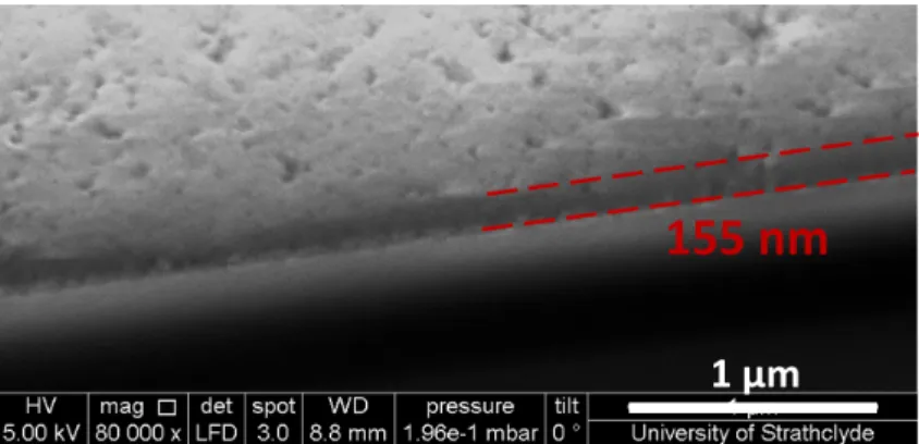
storage. The blending of the CQDs into a PMMA solution was carried out in air and at room temperature and ambient humidity level. First a solution of PMMA in chloroform/toluene was prepared using adequate amount of PMMA powder and an equal amount of chloroform and toluene. The solution was thoroughly mixed using a vortexer and a sonication bath. Then, 1 mg of CQDs in solution were dried out from the toluene content using a membrane vacuum pump. An adequate volume of PMMA solution was then added to the dried CQDs followed by mixing and sonication bath treatment to ensure their full re-dispersion within the new solution. The study of stimulated emission relies on the coating of a cleaned glass slide (n∼1.45) by a thin film of CQD/PMMA material, subsequently annealed in air on a hotplate at 30◦C for 10 min. The cleaning procedure of the glass slide was carried out by subsequent baths in acetone, methanol and deionized water under sonification. Additionally, polymer substrates (NOA85 n∼1.46) were also used to form films of CQD/PMMA. Afterwards, the samples were cleaved using a diamond-tip pen. The surfaces of typical samples were inspected by atomic force microscope giving surface root mean square roughness of 5.6 nm and 6 nm over 20µm × 20 µm areas, respectively, for silica and polymer substrates. A representative film edge scanning electron microscope micrograph of the samples is given in Fig. 2. The thickness of the composite film was estimated to be around 155 nm, which matches the design guidelines shown in Fig. 1.
The DFB cavities were made by templating a silica master containing a one dimensional, second order diffraction grating (with periods of 390 nm or 400 nm and 50 nm modulation depth) with a liquid optical adhesive, which conforms to the master, hardens in the presence of ultraviolet (UV) flooding and enables straightforward release from the master. The optical adhesive was an acrylate-based Norland Products material with a refractive index of∼1.46 (wavelength in the visible not specified) and was supported by a commercial acetate sheet.
Fig. 2. Scanning electron microscopy images showing the edge of a representative cleaved film of CQD/PMMA composite on a Si/SiO2substrate.
A first short exposure (30 s, at∼26.5 mJ/cm2) under UV was realized through the acetate sheet, the acrylate polymer film was then released from the silica master and a final UV cure followed to bring the full curing dose to 3.5 J/cm2. To fabricate the DFB lasers, CQD/PMMA was spin-coated onto the acrylate polymer grating to form a film of the desired thickness. The film was then annealed in air on a hotplate at 30◦C for 10 min.
2.3. Experimental setups
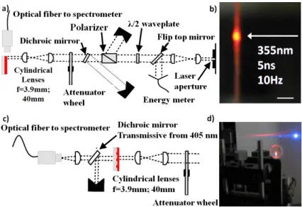
Prior to laser demonstration, thin films of CQD/PMMA on flat substrates were characterized in terms of PL and were assessed for their capabilities to sustain stimulated emission (through detection of amplified spontaneous emission, ASE). The PL spectra were recorded using a Jobin-Yvon TRIAX spectrometer under continuous wave excitation with a 374-nm-emitting laser diode either focused on the sample with a 60× magnification microscope objective for top emission PL (spot size of∼2µm) or focused in a stripe on the side of the sample for edge emission PL (stripe size∼3.5 mm × 0.2 mm). The collection was realized through the same microscope objective. The studies carried out for stimulated emission and DFB lasers were both carried out with a pulsed ultraviolet laser light at a 355-nm wavelength, with 5-ns pulse duration and a 10-Hz repetition rate. Control of the pump energy delivered to the samples was achieved by rotating aλ/2 waveplate followed by a polarizer and an attenuator wheel, while monitoring the value with an energy meter. In both cases, the optical beam was shaped into a collimated stripe of 2.9 mm× 0.3 mm FWHM. The sample emission was collected by a 50-µm-core optical fiber, which was connected to a CCD-spectrometer with respective spectral resolution of 2.5 nm for stimulated emission measurement and 0.13 nm for the DFB lasers. In the case of the stimulated emission studies, emission from the sample edge was collected by the optical fiber (Fig. 3(a)). In the case of the DFB lasers, the emission normal to the device surface was collected, focussed into the optical fiber and the residual pump beam was filtered out with a dichroic mirror. Figure 3(b) is an optical image of the edge of a CQD/PMMA film as seen by the optical fiber under the stimulated emission experiment. Figure 3(c) gives a schematic of the optical setup. Figure 3(d) shows a DFB laser under optical pumping with its fan-shaped emission (red) and the residual non-absorbed pump beam (ultraviolet).
Fig. 3. a) Optical pumping setup for amplified spontaneous emission, b) edge of the film under nanosecond excitation in the stimulated emission regime as seen by the collecting optical fiber (scale bar is 0.4 mm), c) schematic of DFB laser characterisation, d) DFB laser under optical pumping (dichroic mirror removed) (scale bar is 10 mm).
3. Experimental results and discussion
3.1. Photoluminescence and amplified spontaneous emission
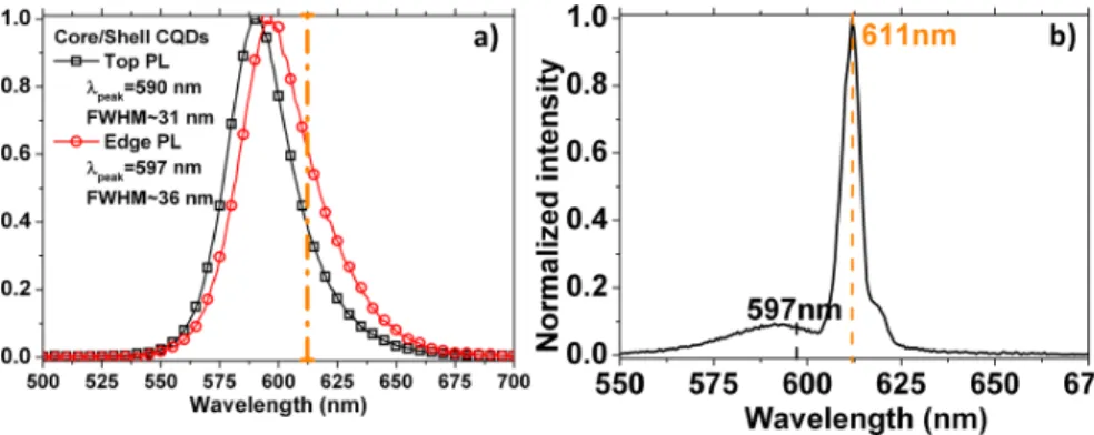
The top and edge PL spectra of CQD films excited in the UV at 371 nm were first measured. The CQDs were at a concentration of 50 mg/mL, dispersed in PMMA solution at 1.6 mg/mL (50/1.6 w/r) and spin-coated on a glass substrate. The top emission PL of the film was recorded and shows that the emission of core/shell CQDs within a PMMA matrix peaks at a wavelength of 590 nm in accordance with the stated value in the data sheet (Fig. 4(a)). The edge PL of the sample is red-shifted by 7 nm (to 597 nm) with respect to the top PL. This is caused by the re-absorption effects of the intrinsic emission as it propagates in the film due to the relatively small Stokes shift (∼20 nm) of the CQDs. In addition, PL quantum yield (PLQY) was measured using an 8-inch integrating sphere and a continuous wave pump source emitting at 450 nm. The resulting PLQY for the aforementioned film of spin-coated CQD/PMMA nanocomposite is 15%.
The evolution of the edge emission from a film under nanosecond optical excitation was investigated using the setup of Fig. 3(a). The spectral shape is seen to significantly change above a certain excitation value (ASE threshold or transparency value) with a narrower peak developing and dominating the PL as the excitation is further increased. Figure 4(b) shows such an ASE spectrum of the core/shell CQDs as recorded at a pumping fluence several times higher than the transparency value. The ASE peak develops around 611 nm with a FWHM of ∼4.4 nm as fitted with a Gaussian curve (fit details not given). The peak value of the ASE is red-shifted compared to the edge PL peak as measured in the edge configuration PL (597 nm, Fig. 4(a). This behavior is typical of core/shell CQDs systems and is attributed to photo-induced absorption phenomena within the CQDs and/or possible bi-exciton binding energy [6]. These results indicate that the CQD/PMMA film can sustain stimulated emission. Hence it can be used as laser gain region.
Fig. 4. a) Top and edge micro-photoluminescence spectra under 371 nm optical excitation of core/shell CQDs dispersed at a concentration of 50 mg/mL in a PMMA solution at 1.6 mg/mL. The sample was processed by spin-coating on a silica substrate. b) Stimulated emission spectrum of the previous film under nanosecond optical pumping. The dashed line in both figures represents the peak wavelength of the stimulated emission spectrum.
Fig. 5. a) Transfer function of the ASE from CQDs/PMMA composite samples spin-coated on glass. These data show different CQD/PMMA w/r combination and how it affects their thresholds. b) Further details on the spectral emission of the ASE peaks for different com-position of materials.
Interestingly, a variation in the composition of the CQD/PMMA composite is reflected in the ASE behavior of similarly processed films and on similar substrates (e.g., amorphous glass in this case). As shown in Fig. 5(a), the ASE for a composite with a lower loading of PMMA (1.6 mg/mL, 50/1.6 w/r) has a threshold about 3-fold smaller at 1 mJ/cm2 in comparison to nanocomposite with 16.6 mg/mL PMMA (50/16.6 w/r). In parallel, the stimulated emission peaks at different wavelengths for these two composites are shown in Fig. 5(b). The most red-shifted ASE peak (611 nm) corresponds to the sample with the highest loading of CQDs. The difference in the stimulated emission spectra is attributed to a higher volume fraction of active material in the spin-coated films with low amount of PMMA. Re-absorption phenomena are then more prominent and affect the ASE development. However, there are also more CQDs participating in the amplification process, thus leading to lower thresholds.
3.2. Distributed feedback lasers demonstrations
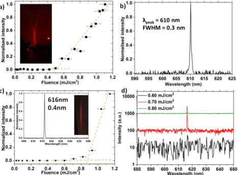
Figure 6(a) shows the transfer function of a typical DFB laser made with a grating periodicity Λ=390 nm and the optimized CQD/PMMA thin-film described previously as the gain layer. An established laser regime with a 0.50-mJ/cm2 threshold is measured for an emission at 610 nm as depicted in Fig. 6(a) and (b), respectively. The spatial distribution of the intensity of the emitted laser beam, pictured in the inset of Fig. 6(a), follows the expected fan-shape typical of a one-dimensional vertical emitting DFB laser. Similar results are obtained for a 400-nm-periodicity DFB laser (Fig. 6(c)). In that case, the threshold is 0.85 mJ/cm2. One can notice a transition region near but below threshold (pump fluence between 0.60 mJ/cm2and 0.85 mJ/cm2) where the increase in intensity is not linear as opposed to the established regime (fluences≥0.85 mJ/cm2). A closer inspection of the spectrum evolution is given in Fig. 6(d) (in logarithmic scale). Stimulated emission with a narrow spectrum is already taking place for pumping fluence between 0.60 and 0.70 mJ/cm2. The resulting “soft” threshold is sometimes observed in DFB lasers made of high-gain thin films and is an indication that a significant amount of spontaneous emission is coupled into the laser mode [22].
Fig. 6. DFB laser demonstrations made using a polymer grating of refractive index 1.46 with core/shell CQDs at a concentration of 50 mg/mL in a PMMA host matrix at 1.6 mg/mL (50/1.6 w/r) with periodicity ofΛ=390 nm (a and b) and Λ=400 nm (c and d). a) and c) are the power transfer functions and b) and d) are the emission spectra of the DFB lasers.
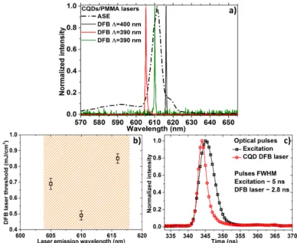
The emission wavelength of our lasers can be set at the design stage by fine-tuning the cavity parameters such as grating periodicity and/or the gain material thickness. Figure 7(a) shows the emission spectra above threshold for 3 lasers made this way, all based on CQD/PMMA gain material. The ASE spectrum corresponding to the equivalent gain film is also displayed for information. Emission is thus shown over a 11 nm range from 605 nm to 616 nm. The threshold fluences for the 3 lasers are presented in Fig. 7(b) and are respectively 0.70, 0.50 and 0.85 mJ/cm2 for emission wavelengths of 605, 610 and 616 nm. As could be expected,
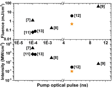
the lowest threshold fluence is found for the oscillation wavelength closest to the maximum of the peak of the stimulated emission spectrum. Figure 7(c) shows the recorded laser pulse from the optical excitation and a CQD DFB laser addressed with a fluence several times the threshold, respectively. These pulses were recorded using a 1-ns-rising time fast photodiode connected to a 500-MHz oscilloscope (equivalent rising time of 0.7 ns). As stated previously, the optical pump delivers pulses of∼5 ns FWHM; in comparison, the DFB laser emits optical pulses∼2.8-ns-long. Lastly, Fig. 8 summarizes the threshold fluences (closed symbols) and power density level (opened symbols) of different published reports of CQD lasers including whispering gallery modes [7, 8, 9], vertical cavity surface emitting lasers [11] and DFB [12, 13] compared to those of the lasers reported here. It is thus shown that this work represents state-of-the-art CQD lasers with a threshold close to 100 kW /cm2.
Fig. 7. a) Discrete tuning demonstration of the distributed feedback lasers based on CQD/PMMA gain layer by varying its film thickness or the grating period (390 and 400 nm). The ASE spectrum is plotted alongside to guide the reader for the maximum of the gain spectrum. b) Summary of the measured threshold to the lasing wavelength. The highlighted region is the 1/e2of the stimulated emission spectrum in the saturated regime. c) Optical pulse duration of the pump and CQD DFB laser.
3.3. Refractive index sensing
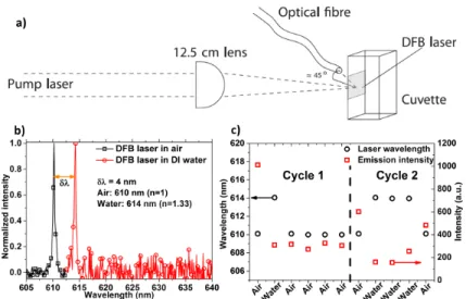
In the previous demonstrations, all results presented were obtained in air, without a cladding layer added on top of the gain material. Following the concept already established by several groups, including ours, in the domain of dye-doped and organic semiconductors DFB laser sensors, we demonstrate in this section the capability of our CQD lasers to operate in a liquid environment and to sense changes in refractive index. The basic principle is based on the fact that a change in the refractive index of the upper cladding medium (the superstrate) induces a modification of the modal effective index and thus leads, following the Bragg equation, to a shift of the DFB laser emission wavelength. It is possible to relate the change of refractive
Fig. 8. Comparison of reported laser thresholds for devices based on CQDs as the gain material expressed in terms of fluence (top section) and power density (bottom section) against the pump pulse duration. Data shown above represent: VCSEL (diamonds), WGM (triangles), DFB lasers (circles) and this work (stars).
index of the top cladding with the laser emission shift, thus enabling sensing capabilities [23]. Here we introduce the same concept but using CQD lasers instead of organic lasers. Water is used in this initial demonstration because i) it forms the base for many biological buffers and ii) it is a solvent these CQDs will not disperse in. In addition PMMA, by its hydrophobic nature, should help in making the sensor robust by ensuring that water does not swell the gain layer. Figure 9(a) details the experimental apparatus to realize sensing using the DFB lasers. A DFB laser is incorporated in a glass cuvette so that the gain material is exposed to its content. The laser is pumped, and the emission is collected, through the backside. Spectra are measured with the same fiber-coupled spectrometer used in the previous experiments. Figure 9(b) gives the results for the DFB laser in contact with air and water; the emission at 610 nm is in air (n=1) and the red-shifted emission at 614 nm is when the laser is in contact with deionised water (n∼1.33). At the same time, there is a drop in intensity by approximatively 70% when the laser is immersed in water as shown by the level of noise in the spectrum. The drop is attributed to an increase of the threshold. Possible reasons for this are still under investigation. Nevertheless, it was verified that this intensity is not detrimental to the sensing function. Figure 9(c) shows 2 cycles of water refractive index sensing with the same CQD DFB device probed at 2 different locations subsequently. Initially in air for the cycle 1, the DFB emits at 610 nm; in water, the emitted wavelength shifts to 614 nm. Alternation of air and water confirm identical shifts throughout the cycles without variations between each measurement (spaced in time by about 1 min). This shows that despite the variation of intensity, the DFB laser wavelength shift is not affected when pumped at a constant fluence. This important result demonstrates the CQD lasers can operate in a polar solvent and are suitable for sensing.
Fig. 9. a) Schematic of refractive index sensing of liquid medium using CQD/PMMA DFB lasers, b) bulk refractive index sensing results of deionised water (n≈1.33), c) wavelength and emission intensity of a DFB laser cycled between air and water media.
4. Conclusion
We have reported on the design and fabrication of DFB lasers made with CQDs as gain materials dispersed in a PMMA matrix to obtain high quality films. Stimulated emission and single transverse mode DFB lasers are demonstrated under 5 ns pulsed excitation at 355 nm for the first time to the authors’ knowledge. DFB lasers with oscillation thresholds as low as 0.50 mJ/cm2 were achieved for 610 nm emission with a FWHM linewidth below 0.3 nm. Optical pumping of such plastic CQD devices with compact solid-state lasers is therefore already possible. Laser emission over 11 nm, from 605 to 616 nm, is also shown by tuning the cavity parameters, e.g., gain material thickness and/or the periodicity of the DFB grating. Finally, the first step towards the usage of CQD DFB lasers in a “real-world” application was taken with the demonstration of laser operation in a liquid environment. A 4 nm red-shift of the DFB laser emission was detected upon immersion in water. Overall, this study demonstrates the potential of CQD lasers for future applications.
Acknowledgments
The help of Dr. P. Edwards from the Physics Department of the University of Strathclyde for scanning electron microscopy is gratefully acknowledged. This work was supported under the EPSRC projects EP/J021962/1, EP/I029141/1 and EP/K004670/1. HVD, HDS, EM and YG also gratefully acknowledge support from Singapore National Research Foundation under the project NRF-CRP-6-2010-02 and NRF-RF-2009-09. HVD also wishes to acknowledge ESF-EURYI and WBA-Turkish National Academy of Sciences.