I
I”
212 IEEE TRANSACTIONS ON CIRCUITS AND SYSTEMS-I: FUNDAMENTAL THEORY AND APPLICATIONS, VOL. 40, NO. 4, APRIL 1993
for some E
>
0. Let K EW”
be defined as K % = k for all i E { 1 , . ..
,
n}. Define the following change of variables:w ( t ) =
iqt)
+
K. (19)Then U J satisfies
We show that the FDE in (20) satisfies assumptions H - 1. H - 2, H - 3, and H - 5 in [15]. It is easy to verify that G(2r;)
5
0 and G( 0)2
0. Therefore, assumption H - 3 is satisfied. AssumptionH - 1 is satisfied because G- is globally Lipschitzian [15, remark 41.
H - 2 is satisfied because
A
has nonnegative off-diagonal elements and AT has nonnegative elements. To show that H - 5 is satisfied, let<,
q EW;
be such that5
q and#
q. Leti
be an index such that f ( q t - ti) -f(<;
- K ) has the largest value. It is clear that we can choose i such that q2 - (t>
0. ThenGt(E) - Gt(7/) 1 = ‘ V Z
-
E ,
+
C(.i
+
mt,(i(<]
- K ) - f ( q , - K ) ) 3 = 1 n2
r/i - <z+
( j ( +
- K ) -j ( ~ t
-2
111 - Ei>
0.(i
+
z i r ) q , = l (21) Where we have used the assumption thatE;==,
-(d
+
2
0for all i . Therefore, H
-
5 is satisfied.By [15, lemma 31, for all initial conditions in C r ’ znl the trajectory of (20) will converge to one equilibrium point. This means that for all initial conditions in CkpK’ all trajectory of (2) will converge to an unique equilibrium point. By definition of k , all trajectories will eventually enter [ - K , K ] . Therefore, for any trajectory E( t ) , there exists T
>
0 such that $T(.) E CL-“. and the unique equilibrium The property of having a globally asymptotically stable equilibrium point allows such a CNN to be used as a pattern classifier or encoder [ 1 11 in the sense that there is a nonlinear map that relates the steady- state output to the input independent of the initial conditions. One could also view these C N N ’ s as solving nonlinear equations in the sense that given any initial condition, the CNN will converge to the unique solution of a set of nonlinear algebraic equations with the set of equations being solved depending on the input.point is globally asymptotically stable.
IV. CONCLUSIONS
Simple and useful stability conditions have been presented in this paper for the case when the templates are dominant nonlinear and delay -type.
REFERENCES
L. 0. Chua and L. Yang, “Cellular neural networks: Theory,” IEEE Trans. Circuits Syst., vol. 35, pp. 1257-1272, 1988.
L. 0. Chua and L. Yang, “Cellular neural networks: Applications,” IEEE Trans. Circuits Syst., vol. 3 5 , pp. 1273-1290, 1988.
Proc. 1990 IEEE Int. Workshop on Cellular Neural Networks and Their Applications 1990.
T. Roska and L. 0. Chua, “Cellular neural networks with nonlinear and delay-type template elements,” in Proc. IEEE Int. Workshop on Cellular Neural Networks and Their Applications, pp. 12-25, 1990.
W. Heiligenberg and T. Roska, “On biological sensory information processing principles relevant to dual computing CNN’s,” Rep. DNS-4- 1992, Dual and Neural Comp. Sys. Res. Lab., Comp. Aut. Inst., Hung. Acad. of Sci., Budapest, Mar. 1992.
L. 0. Chua and T. Roska, “Stability of a class of nonreciprocal cellular neural networks,” IEEE Trans. Circuits Syst., vol. 37, pp. 1520-1527,
1990.
L. 0. Chua and C. W. Wu, “On the universe of stable cellular neural networks,” Int. .I.Circuir Theory and Applications, vol. 20, 1992. T. Roska, C. W. Wu, M. Balsi, and L. 0. Chua, “Stability and dynamics of delay-type general and cellular neural networks,” IEEE Trans. Circuits Syst.-I, vol. 39, pp. 487490, June 1992.
-, “Stability and dynamics of delay-type and nonlinear cellular neu- ral networks,” ERL Memorandum UCB/ERL M91/110, Univ. California, Berkeley, 199 1.
P. P. Civalleri, M. Gilli, and L. Pandolfi, “On stability of cellular neural networks with delay,” Tech. Rep., Politecnico di Torino, 1992. D. G. Kelly, “Stability in contractive nonlinear neural networks,” IEEE Trans. Biomedical Eng., vol. 37, pp. 231-242, Mar. 1990.
J. K. Hale, Theory of Functional Diflerential Equations, vol. 3 of Applied Mathematical Sciences.
T. Roska, “Some qualitative aspects of neural computing circuits,” in Proc. IEEE Int. Symp. Circuits Syst., pp. 751-754, 1988.
T. Roska, J. Himori, E. Labos, K. Lotz, L. Orz6, J. Takics, P. Venetianer, 2. Vidnyinszky, and A. Zarindy, “The CNN model in the visual pathway-part 11: The amacrine cell in the modified retina model, simple LGN effects, and motion related illusions,” Tech. Rep. DNS-9.1992, Comp. Aut. Inst. Hung. Acad. Sci., Budapest, 1992. Y, Ohta, “Qualitative analysis of nonlinear quasi-monotone dynamical systems described by functional-differential equations,” IEEE Trans. Circuits Syst., vol. CAS-28, pp. 138-144, Feb. 1981.
New York: Springer-Verlag. 1977.
Biquadratic Transconductance Switched-Capacitor Filters
Mehmet Ali Tan
Abstract- Switched-capacitor (SC) filters yield efficient implemen-
tations in integrated form. However, they employ op-amps, each of
which must be designed for a given filter separately. Furthermore, SC
filters are not tunable. This work presents a new type of sampled data filters consisting of transconductance elements, switches and capacitors, called transconductor switched capacitor (TSC) filters. Transconductance elements do not degrade their performance within a wide frequency range and tunable ones are available.
I. 1NTRODUCTlON
In many real-time signal processing applications, analog sampled data filters are suitable because of the speed and the silicon area saved from analog-to-digital and digital-to-analog conversion hardware. The improvements in switched-capacitor ( S C ) filters have almost reached a saturation [I]. SC filters are not tunable. Accordingly, the precision of the coefficients can be increased only by increasing the area consumed by the capacitors. Furthermore, the finite op-amp gain- bandwidth degrades the performance of SC filters at relatively high frequencies [2]. The op-amps in SC filters must be compensated for stability purposes since they are always used in continuous feedback Manuscript received December 2, 1991 ; revised November 17, 1992. This The author is with the Department of Electrical 5; Electronics Engineering, IEEE Log Number 9208190.
paper was recommended by Associate Editor D. J. Allstot. Bilkent University, Bilkent 06533, Ankara, Turkey.
IEEE TRANSACTIONS ON CIRCUITS A N D SYSTEMS-I: FUNDAMENTAL THEORY AND APPLICATIONS, VOL. 40, NO. 4, APRIL 1993
Fig. 1. (a) TSC integrator circuit and (b) its signal flow graph.
and must be optimized individually for given loading capacitance in order to save silicon real-estate.
This discussion suggests that transconductance elements are more suitable as active building blocks in CMOS technology. As a matter of fact, the op-amp implemented in CMOS technology behaves as a dif- ferential transconductor amplifier. Tunable and versatile transconduc- tance elements are readily available [ 3 ] . However, Transconductance- C [4] or OTA-C [ 5 ] filters require small transconductance parameters or large capacitances which are almost infeasible for monolithic realizations in medium and low frequency range such as from the voice band to several hundred kilohertz. The switched-current filters
[6] need accurate current mirror circuits because the filter coefficients are set by the current mirror ratios.
In order to some of the difficulties posed by other filter classes and capture the advantages they possess, this work introduces the transconductance switched-capacitor (TSC) filters. The TSC filters have the opportunity of using the tunable transconductances available. Furthermore, in comparison with the op-amps in SC filters, they do not need any compensation because continuous capacitive feedback does not exist in TSC filters. The filter coefficients of a TSC filter are set by the transconductance parameters, capacitor values, the clock period, and the clock pulse width.
The synthesis of TSC filters is presented based on the signal flow graph approach. The basic TSC circuits are introduced in Section 11. The synthesis of TSC circuits is explained in Section 111. A bandpass filter example is presented in Section IV.
11. BASIC BUILD~NC BLOCKS
The basic building blocks for the TSC ladder filters are summing discrete integrator and voltage summing circuit. All the basic circuits contain transconductance elements. A transconductance element can be modeled by a voltage controlled current source with the parameter
.Y,,~. ,Y,,~ may be negative and can be obtained from the transconduc- tance with positive ,Y?,~ by a voltage inverter its input. The switches are controlled by a nonoverlapping two-phase clock with a period
T . The pulse width for the phase 01 is T . This waveform can be
generated easily by a monostable circuit. The pulse width r can be tuned by varying the time constant of the monostable circuit. The input and output signals are assumed to be sampled at the end of 0,.
_ -
g o
(b)
Fig. 2. (a) TSC summing circuit and (b) its signal Row graph.
213
Fig. 3. A signal flow graph realizing H ( z ) given in (3).
Integrator Circuit
In the transconductor SC integrator circuit shown in Fig. l(a), the integrator capacitor is charged by the output currents of the transconductors y,,,,, and g n l p in a rate which is proportional to the piecewise-constant input signals I;, and 1; during d1. By solving the simple first order differential equation valid during dl for the initial condition remained from the previous period, and taking the z-transform of the difference equation obtained, the input-output relationship of the integrator in the z-domain can be easily derived as
The {I,, transconductances and the capacitor C s t o are, respectively, used to form a voltage buffer and hold the final value of the capacitor
C,,,, at the output on the next 01 phase. Hence, their values do not have any significant effect on the transfer function and therefore are not important. The only requirement upon them is that the voltage of
C+to should be able to rise during ol. Accordingly, C s t o / g , ,
<<
T-Tcondition must be satisfied. A small capacitance value may be sufficient for this purpose. A signal flow graph of the integrator circuit can be easily derived from ( 1 ) as shown in Fig. I(b).
Summing Circuit
Fig. 2(a) realizes the signed summation of two inputs as
It can be easily shown that the transconductance circuit shown in
by simply writing a node equation for the output node and using the definition of transconductance elements.
0 h
%
2
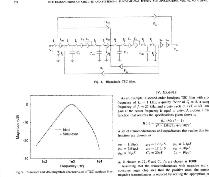
a, -10 U 3 C (5, c .- -20Fig. 4. Biquadratic TSC filter.
IV. EXAMPLE
As an example, a second-order bandpass TSC filter with a center frequency of fo = 1 kHz, a quality factor of Q = 2, a sampling frequency of f(. = 25 kHz, and a duty cycle of
TIT
= 5%, and the gain at the center frequency is equal to unity. A z-domain transfer function that realizes the specifications given above is0 . 1 4 8 9 ( ~ ' - 1) z' - 1.&4272
+
0.7022'H ( z ) = (4)
(3)
By using well-known Mason's gain formula, it can be easily verified that the signal flow graph presented in Fig. 3 realizes H ( z ) in (3). Note that the signal flow graph of Fig. 3 is composed of two types of subgraphs, one of which is integrator signal flow graph given in Fig. 1 and the other of which is the signal flow graph of the summing circuit given in Fig. 2. By appropriately interconnecting the subcircuits corresponding to the signal flow graph branches by appropriate element values based on the basic TSC circuits shown in Fig. 1 and Fig. 2, the resulting transconductor switched capacitor circuit is obtained as shown in Fig. 4.
v.
CONCLUSIONA new class of sampled data filters, called TSC's filters, has been presented. The synthesis of TSC filters is explained based
on a signal flow graph realizing the general z-domain biquadratic transfer function. TSC filters employ transconductance elements as active devices that are readily available in various technologies and easily implemented and more suitable than op-amps in a CMOS
technology. Because the building blocks are not involved in any continuous feedback any frequency compensation is not necessary for the stability purposes. The filter coefficients are determined by the clock pulse width and the transconductances, both of which can be tuned, and the integrator capacitors. This method can be easily generalized to the higher order filters.
275
REFERENCES
R. Schaumann, K. R. Laker, and M. S. Ghausi, Design ofAnalog Filters: Passive, Active RC and Switched-Capacifor. Englewood Cliffs, NJ: Prentice-Hall, 1990.
K. Martin and A. S. Sedra, “Effects of the op-amp finite gain and band- width on the performance of switched-capacitor filters,” IEEE Trans. Circuifs Syst., vol. CAS-28, pp. 822-829, August 1981.
C. S. Park and R. Schaumann, “A high-frequency CMOS linear transconductance element,” IEEE Trans. Circuits Sysf., vol. CAS-33,
R. Schaumann and M. A. Tan, “Continuous-time filter,” in C. Toumazou,
F. J. Lidgey, and D. G. Haigh, eds., Analogue IC Design: The Current- Mode Approach, ch. 9, pp. 371-386. London: Peter Perenigus, 1990. E. SBnchez-Sinencio, R. L. Geiger, and H. Nevarez-Lozano, “Generation of continuous-time two integrator loop OTA filter structures,” IEEE Trans. Circuifs Sysf., vol. 35, pp, 936946, Aug. 1988.
J. B. Hughes, “Switched-current filters,” in C. Toumazou, F. J. Lidgey, and D. G. Haigh, eds., Analogue IC Design: The Current-Mode Ap- proach, ch. 11, pp. 415450.
H. Khorramabadi and P. R. Gray, “High-frequency CMOS continuous- time filters,” IEEE J. Solid-Stare Circuits, vol. SC-19, pp. 939-948, Dec. 1984.
C. S. Park and R. Schaumann, “Design of a 4 MHz analog inte- grated CMOS Transconductance-C bandpass filter,” IEEE J. Solid-Sfate Circuifs, vol. SC-23, pp. 987-996, Aug. 1988.
pp. 1132-1 138, 1986.
London: IEE, 1990.
Feedback Analysis of Transimpedance
Operational Amplifier Circuits
Erik Bruun
Abstract-The transimpedance or current feedback operational ampli- fier (CFB op-amp) is reviewed and compared to a conventional voltage mode op-amp using an analysis emphasizing the basic feedback charac- teristics of the circuit. With this approach the paradox of the constant bandwidth obtained from CFB op-amps is explained. It is demonstrated in a simple manner that the constant gain-bandwidth product of the conventional op-amp and the constant bandwidth of the CFB op-amp are both in accordance with basic feedback theory and that the differences between the traditional op-amp and the CFB op-amp are due to different ways of controlling the closed-loop gain. For the traditional op-amp the closed-loop gain is altered by altering the loop gain whereas the closed- loop gain in a CFB op-amp configuration is altered by altering the input attenuation to the feedback loop while maintaining a constant-loop gain.
I. INTRODUCTION
The transimpedance or current feedback operational amplifier (CFB op-amp) as introduced by Nelson and Evans [ I ] has been available as a monolithic op-amp for a number of years. One of the most prominent features of this amplifier is the constant bandwidth, independent of the closed-loop voltage gain in a feedback configuration. This characteristic has been treated in the literature as a property almost violating traditional feedback theory that prescribes Manuscript received September 3 , 1992; revised January 6, 1993. This paper E. Bruun is with the Electronics Institute, Building 349, Technical Univer- IEEE Log Number 9208194.
was recommended by Associate Editor B. S. Song. sity of Denmark, DK-2800 Lyngby, Denmark.
that an amplifier with feedback has a constant product of closed- loop gain and bandwidth [2], [3]. Hence, an analysis of the CFB
amplifier with reference to familiar concepts in feedback theory seems appropriate.
11. THE VOLTAGE MODE OPERATIONAL AMPLIFIER Fig. 1 shows a traditional voltage mode op-amp in both an inverting and a noninverting feedback configuration. Assuming that the op- amp differential voltage gain is &(S) we find the signal flow graphs
shown in Fig. 2. From these we find the closed loop A ( s ) and the
loop gain T ( s ) :
For the inverting amplifier we note that
(3)
For the noninverting amplifier we find
Assuming that A d ( S ) = & / ( 1
+
s / d C ) we find the closed-loop gain and bandwidth relations2 ~ B l l . ~ = d C ( 1 - )J&) (7) and
27rGBTT7 = ~ d ~ ~ l o . (8) For the noninverting amplifier of Fig. l(b) with o = 1 the latter expression shows that the product of gain G and bandwidth BW’ is constant and equal to the unity gain bandwidth A O L J ~ / ~ K for the op-amp. For the inverting amplifier (8) shows that the product of gain and bandwidth is actually not constant as a is dependent on the closed-loop gain. Assuming ;lo
>>
1 we note that the low frequency gain is G = - o / B = - R 2 / R 1 implying that (8) for the inverting configuration results in(9) Only for IGI
>>
1 does this equation express a constant gain- bandwidth product.An important property of feedback is that it reduces distortion, sensitivity to component variations, etc., with a factor of F ( s ) = 1
+
T ( s). For the configurations based on voltage mode operational amplifiers we findObviously, F ( s ) is dependent on the gain G and hence the improve- ments in distortion, sensitivity, etc., are strongly dependent on G (approximately inversely proportional to G).