operation bandwidth of DCS1800 and PCS1900 bands. This makes the proposed antenna cover the frequency bands of GSM900, DCS1800, and PCS1900 simultaneously.
The radiation characteristics of the presented antenna have also been studied. Figures 4 and 5 show the simulated radiation patterns of the flexible antenna at the central frequency of GSM/DCS/PCS bands in E-plane and H-plane, respectively. It can be seen that the radiation patterns in H-plane is omni-directional, and the radiation patterns in E-plane is nearly omni-directional although there exists some aberrance. In addition, the gain and total efficiency of the proposed antenna and the antenna without the metallic rod are plotted in Figures 6 and 7, respectively. One can see that the peak gain and total efficiency of the proposed antenna can meet the demands required by mobile applications. Moreover, one can also conclude that the metallic rod introduced in the antenna design can also improve the gain and efficiency of the flexible antenna in the GSM/DCS/PCS bands.
4. CONCLUSIONS
A compact flexible PIFA with a rolled radiating arm and a metallic rod for GSM/DCS/PCS operation is proposed and studied. The
PCS resonant mode is excited by the metallic rod that works as the parasitic element of the proposed antenna; and most importantly, the antenna construction stability is obviously improved by this metallic rod. The antenna prototype was fabricated and measured. Good agreement between the measurement and simulation has been observed. Compared with the antenna design [3], the pro-posed antenna is more suitable for use in portable communication devices because of its construction stability and wider bandwidth in the high band.
REFERENCES
1. Y.-X. Guo, I. Ang, and M.Y.W. Chia, Compact internal multiband antennas for mobile handsets, IEEE Antennas Wireless Propag Lett 2 (2003), 143–146.
2. H.-T. Chen, K.-L. Wong, and T.-W. Chiou, PIFA with a meandered and folded patch for the dual-band mobile phone application, IEEE Trans Antennas Propag 51 (2003), 2468 –2471.
3. F.-R. Hsiao, T.-W. Chiou, and K.-L. Wong, Dual-frequency planar inverted-F antenna with a rolled radiating arm for GSM/DCS operation, Microwave Opt Technol Lett 38 (2003), 25–27.
4. J. Jung, H. Lee, and Y. Lim, Broadband flexible meander line antenna with vertical lines, Microwave Opt Technol Lett 49 (2007), 1984 –1987. 5. W.-C. Liu and C.-F. Hsu, Flexible CPW-fed double meandered mono-pole antenna for dual-band WLAN operation, Microwave Opt Technol Lett 48 (2006), 1529 –1532.
6. CST-Microwave Studio, Computer Simulation Technology, Darmstadt, Germany, 2008.
© 2009 Wiley Periodicals, Inc.
METAMATERIAL SLABS AND
REALIZATION OF ALL-TYPE FILTER
CHARACTERISTICS: NUMERICAL AND
ANALYTICAL INVESTIGATIONS
Sibel C¸ ı˙men,1Gonca C¸ akir,1and Levent Sevgı˙2
1Electronics and Communication Engineering Department, Kocaeli
University, Kocaeli, Turkey; Corresponding author: [email protected]
2Electronics and Communication Engineering Department, Dog˘uçs
University, Zeamet Sok. No.21, Acıbadem/Kadıko¨y, I˙stanbul, Turkey
Received 31 July 2008
ABSTRACT: Studies towards understanding and the use of metamaterials
(MTM) have risen in electromagnetic engineering. This article presents analytical and numerical investigations of filter characteristics of MTMs in two-dimension (2D). Numerical investigations are based on finite difference time domain (FDTD) simulations, analytical formulations belong to a plane wave excitation of multi-slab structures. It is shown that a three layer struc-ture with different combinations of MTMs and non-MTMs may be used to realize all four types of filter characteristics. © 2009 Wiley Periodicals, Inc.
Microwave Opt Technol Lett 51: 894 – 899, 2009; Published online in Wiley InterScience (www.interscience.wiley.com). DOI 10.1002/mop. 24196
Key words: metamaterial; double negative; double positive; left
handed; multilayered slabs; S-parameters; finite-difference time-domain method; FDTD; microwave filters; low pass filter; band pass filter; high pass filter; band stop filter
1. INTRODUCTION
Metamaterials (MTMs) have attracted much attention recently because of their potential applications. Materials with simulta-neously negative permittivity and permeability over a certain fre-Figure 6 Antenna gain of the proposed antenna and the antenna without
rod. [Color figure can be viewed in the online issue, which is available at www.interscience.wiley.com]
Figure 7 Total efficiency of the proposed antenna and the antenna without rod. [Color figure can be viewed in the online issue, which is available at www.interscience.wiley.com]
quency band (which are also called left-handed materials—LHM, or double negative (DNG) materials) were first studied by Vese-lago [1]. Electric and magnetic fields, and the wavevector of an electromagnetic (EM) plane wave in such materials form a left-handed system. One of the earliest and important applications of MTMs is the perfect lens [2]. The MTMs introduce peculiar yet interesting properties such as negative refraction, reversed Doppler effect, and reversed Cerenkov radiation, etc, [3].
There have also been great efforts on the numerical modeling of MTMs. Studies on numerical MTM modeling may be grouped into two. The first group use mathematical models (expressions) for dispersive materials (e.g., [2]), but the other try obtain MTM response with an array of split ring resonators (SRRs) and arrays of metallic wires [4]. The finite-difference time-domain (FDTD) method has been widely used in the numerical modeling of EM wave—MTM interaction [3–12].
This article focuses on the extraction of filter characteristics of two dimensional (2D), infinite-extend multi-layer DNG and DPS slabs analytically as well as numerically. The virtual tool MGL-2D [13] which can be used to investigate broad range of EM problems with DPS materials was modified to include DNG materials (i.e., 2D dispersive FDTD code was developed) [14]. The virtual MTM-FDTD tool presented in [14] can be used to visualize EM wave-MTM interactions for various wave-MTM geometries and in different frequency ranges. It can also be used to record these interactions as video clips in the time domain. The SLAB-MTM is a modified version of MTM-FDTD [15, 16] and can be used to obtain reflec-tion and transmission characteristics for various multi-layer DPS-DNG slabs. In SLAB-MTM, infinite-extend DPS and DPS-DNG slabs are modeled using periodic boundary conditions (PBC) in the transverse domain. The TExtype solutions with the field compo-nents Ex, Ey, and Hzare considered [note that the problem reduces
to a plane-wave excitation with two orthogonal field components Ey and Hz in the transverse yz-domain propagating along ⫾ x
directions; Ex ⫽ 0 (see Fig. 2)]. Numerical results belong to
SLAB-MTM simulations. Analytical formulations are taken from [17]. A canonical three-layer slab with different combinations of DPS-DNG characteristics is used to realize all four type (band pass, band stop, high pass, and low pass) filters.
2. FDTD-BASED MODELING AND THE SLAB-MTM
The FDTD method is versatile, robust, and has been widely used for the modeling of EM wave interactions with various frequency dispersive materials. To model EM wave, MTM interaction the dispersive FDTD equations are needed. Among a few, auxiliary differential equation (ADE) proposed in [18] is used here. There-fore the 2D TE-type MTM-FDTD [13] virtual tool is coded with ADE-FDTD equations (the whole set of 2D ADE-FDTD equations are listed in Table 2 of [14].
An example of EM wave—MTM slab interaction is shown in Figure 1. In Figure 1(a), the front panel of the MTM-FDTD and a scenario with two DNG blocs, located one apart from the other, and a Gaussian beam type continuous wave (CW) excitation are shown during the FDTD simulations. The figure belongs to early time response just before the beam hits the first DNG block. Two instants from late time response are given in Figure 1(b). On the top, negative reflections from both vertical boundaries of the first DNG block is shown. On the bottom, the snapshot belongs to late time response after the Gaussian beam interacts with both DNG blocks.
The front panel of SLAB-MTM used in this article is exactly the same with the MTM-FDTD virtual tool. The modifications included in the SLAB-MTM are as described in Figure 2. To
extract S-parameters of multi-layer DPS and/or DNG slabs in 2D, one need to locate infinite-extend layers vertically and send the pulsed plane wave from one end. These are achieved by the application of PBC as the top and bottom terminations as shown in the figure. The left and right terminations are left as PML blocks as in MTM-FDTD virtual tool. The S-parameter extraction proce-dure is based on sending the pulsed plane wave from left, running the dispersive FDTD simulations, recording reflected and trans-mitted time signals at the two observation points (Obs-1 and Obs-2 in Fig. 2), and applying off-line discrete or fast Fourier transform (DFT or FFT).
The simulation window in the SLAB-MTM tool is, by default, a 800⫻ 400 cell space, terminated by 20-cell PML layers from the left and right. The top right is the Simulation block. The buttons START, PAUSE, and STOP can be used to run, pause, and terminate the time domain FDTD simulations. The progress of the simulation is also shown on this block. The beauty and strength of Figure 1 The 2D MTM-FDTD virtual tool and EM wave—MTM inter-action with two rectangular DNG blocks in the time domain; (a) The formation of a CW Gaussian beam (early time response), (b) two late-time snapshots showing negative reflections in both DNG blocks. [Color figure can be viewed in the online issue, which is available at www.inter-science.wiley.com]
the SLAB-MTM is that the whole or any part of the simulation can be recorded and video clips can be prepared.
The DNG parameters for each DNG slab are chosen as in Lorentz model [14]:
D共兲 ⫽ 共兲 E共兲 ⫽ 0关⬁⫹e共兲兴E共兲 (1)
B共兲 ⫽ 共兲 H共兲 ⫽ 0关⬁⫹m共兲兴H共兲. (2)
with electric and magnetic susceptibilities specified as
e,m⫽
冘
k bk ␣k⫹ i 䡠 2 䡠␦k冉
k冊
⫺冉
k冊
2 (3)where bkiskorkis the constants for eor m, respectively,
which may or may not be the same.
This multi-slab geometry may be assumed as a two-port circuit, and reflection/transmission characteristics can be obtained via the calculation of S-parameters. Electric field values at port 1 and 2 are equal to E1共t兲 ⫽ E1⫹共t兲 ⫹ E1⫺共t兲 and E2共t兲 ⫽ E2⫹共t兲 ⫹ E2⫺共t兲 where terms with plus and minus signs represent incident and reflected waves, respectively. The reflection coefficient is then directly equal to R共 f 兲 ⫽ S11共 f 兲 ⫽ E1⫺共 f 兲/E1⫹共 f 兲 because
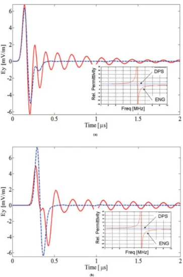
E2⫹共 f 兲 ⫽ 0 (PML termination at both ends). Similarly, the trans-mission coefficient is calculated as T( f )⫽ S21( f )⫽ E2⫺( f )/E1⫹(f) because E1⫺共 f 兲 ⫽ 0 is satisfied. This necessitates running the FDTD simulations twice without and with the geometry present between the two observation points [E1⫹共t兲 is directly recorded at port 1 if there the geometry is not present]. All field values are recorded in the time domain, and their frequency domain values are obtained via off-line DFT or FFT. Figures 3(a) and 3(b) present time signals recorded during SLAB-MTM of a single layer at observation points Obs-1 and Obs-2, and dashed and solid lines represent ENG and DPS materials, respectively. The ENG material has resonance characteristics around 6 GHz. Away from this resonance region both ENG and DPS materials haver⫽ 2 and
r ⫽ 1 . Highly oscillatory nature of the ENG (in general, DNG)
material in this time behavior shows that much longer FDTD simulation durations are required in the S-parameter extraction process.
3. MULTILAYERED SLABS AND ANALYTICAL REPRESENTATIONS
The configuration space of the problem considered is pictured in Figure 2. Here, a plane wave on the left and multi layer slabs with boundaries at x ⫽ d1, x ⫽ d2, . . . , and x ⫽ dtare shown. The
first (n ⫽ 0) and the last (t ⫽ n ⫹ 1) regions are horizontally semi-infinite DPS materials and may be assumed as the input and output ports of this two-port system. The permittivity and perme-ability in each region are denoted bylandl(l⫽ 1,2, . . . , n).
The plane wave is represented by the Hzfield coming from the left. The DPS and DNG materials are characterized with their permit-tivities and permeabilities ( ⬎ 0, ⬎ 0) and ( ⬍ 0, ⬍ 0), respectively. The incident magnetic field Hzis assumed to have
unit amplitude.
There are multiple reflections and transmissions inside each layer and n ⫹ 1 boundaries which give rise to (2n ⫹ 2) equations. In regions 0 and t, only reflection and transmission coefficients, respectively, are required. Because each layer has neighboring relations with only two other layers on its left and right, the matrix system with these (2n⫹ 2) equations form a tri-diagonal system. The solution of this tri-diagonal system yields the total reflection coefficient (for a multi-layer slab) as [17]
Figure 2 The scenario of the 2D SLAB-MTM virtual tool. The disper-sive FDTD space is terminated by PML blocks on the left and right ends. PBC blocks are used on the bottom and top ends. A plane wave is sent from the left onto a multi-layer DPS-DNG structure. [Color figure can be viewed in the online issue, which is available at www.interscience.wiley.com]
Figure 3 Ey vs. time of a plane wave hitting single DNG and DPS layers; (a) at port-1, (b) at port-2. [Color figure can be viewed in the online issue, which is available at www.interscience.wiley.com]
R⫽e i2k0d1 R0,1 ⫹ 关1 ⫺ 共1/R0,1 2 兲兴ei2共k1⫹k0兲d1兩 共1/R0,1兲ei2k1 d1 ⫹ ei2k1d2 R1,2 ⫹关1 ⫺ 共1/R1,22 兲兴ei2共k2⫹k1兲d2兩 共1/R1,2兲ei2k2d2 ⫹ . . . ⫹ ei2kn⫺1dn Rn⫺1,n ⫹关1 ⫺ 共1/Rn2⫺1,n兲兴ei2共kn⫹kn⫺1兲dn兩 共1/Rn⫺1,n兲ei2kndn ⫹ Rn,te i2kndn⫹1 (4)
where Rl,l⫹1is the local reflection coefficient between the boundary
of two neighboring slabs (slab l and l⫹1) and given as
Rl,l⫹1⫽ 1⫺l,l⫹1 1⫹l,l⫹1, l,l⫹1⫽ lkl⫹1 l⫹1kl . (5)
For the three-layer canonical structure (n ⫽ 3 ) discussed in this article the reflection coefficient can be calculated from
R⫽e i2k0d1 R0,1 ⫹ 1 ⫺ 共1/R0,12 兲ei2共k1⫹k0兲d1 共1/R0,1兲ei2k1 d1⫹d i2k1d2 R1,2 ⫹ 关1 ⫺ 共1/R1,22 兲兴ei2共k2⫹k1兲d2 共1/R1,2兲ei2k2 d2⫹e i2k2d3 R2,3 ⫹ 关1 ⫺ 共1/R2,3 2 兲兴ei2共k3⫹k2兲d3 共1/R2,3兲ei2k3 d3⫹ R 3,4䡠 ei2k3 d4 . (6)
The transmission coefficient needs the solution of matrix equation in the form of T⫽ Vញ4,0
冋
1 R册
; Vញ4,0⫽ Vញ4,3䡠 Vញ3,2䡠 Vញ2,1䡠 Vញ1,0 (7) Vញl⫹l,l⫽ 1 2关1 ⫹l⫹1,l兴冋
e⫺i共kl⫹1⫺kl兲dl⫹1 R l⫹1,le⫺i共kl⫹1⫹kl兲dl⫹1 Rl⫹1,lei共kl⫹1⫹kl兲dl⫹1 ei共kl⫹1⫺kl兲dl⫹1册
. (8)Equations (6)–(8) can be used to calculate reflection/transmission coefficients of both DPS and DNG slabs, as well as their different combinations [5, 10, 15, 16].
4. THREE-LAYER DPS-DNG SLABS AND FILTER CHARACTERISTICS
ENG materials act as a low pass filter (LPF) or a notch-type filter depending on its material parameters, but DNG materials yield a
band stop characteristics if frequency characteristics of its permit-tivity and permeability are not the same (共 f 兲 ⫽共 f 兲 ). These two materials can be used to realize all four types of filters. Although this could be also achieved by at least two slabs, a three-layer with different DNG-DPS combinations is preferred in this study be-cause of their full symmetry and better frequency characteristics. First application belongs to a band pass filter (BPF) as shown in Figure 4. The combination of three slabs is also given in the Figure 4 Reflection and transmission characteristics of the three-layer
BPF structure (solid: analytical; dashed: FDTD). The combination is DNG-ENG-DPS. [Color figure can be viewed in the online issue, which is available at www.interscience.wiley.com]
TABLE 1 Parameter Values for BPF Slabs (Source Bandwidth Bⴝ 10 MHz) (w)/ (w) DNG ENG DPS (w) (w) (w) (w) (w) (w) ⬁/⬁ 1 1 1 1 2 1 k/k 3 3 4 0 0 0 ␣k 0 0.227 2.78 0 0 0 ␦k 0 0 0 0 0 0 wk[MHz] 0.7⫻ B 0.7⫻ B 0.7⫻ B 0 0 0
Figure 5 Reflection and transmission characteristics of the three-layer BSF structure (solid: analytical; dashed: FDTD). The combination is DNG-DPS-DNG. [Color figure can be viewed in the online issue, which is available at www.interscience.wiley.com]
figure. Here, the layers are organized as DNG-ENG-DPS slabs having the same thickness. The parameters of this example are listed in Table 1.The parameters are chosen in a way that the first DNG slab has a stop band characteristic in 0 –2 MHz frequency region. The cut-off frequency of the second ENG slab is around 7 MHz. The combination of these two yields BPF characteristics between 2 and 7 MHz. The third DPS layer is used to minimize ripples around the transition frequencies. Solid and dashed lines belong to analytical and numerical results, respectively. As ob-served, there is a very good agreement between analytical and numerical simulations.
Second application belongs to a band stop filter (BSF) example and is given in Figure 5. Although BSF characteristics may also be obtained with a single DNG slab, a DNG-DPS-DNG combination is used to improve BSF characteristics. The permittivity and
permeability of both DNG slabs are chosen in a way to yield resonance effects around 2 MHz and 7 MHz. The parameter values of this example are shown in Table 2. Again, solid and dashed lines belong to analytical and numerical results, respectively, and the good agreement between the results is clearly shown.
The next application belongs to a high pass filter (HPF) structure as shown in Figure 6. Here, a DNG slab is located between two DPS layers. The parameters are listed in Table 3. The lower resonance frequency of the DNG material is reduced to zero, the upper resonance is set to 4 MHz, and HPF charac-teristic is obtained with a cut-off frequency around 4 MHz. The parameters of the two DPS layers at the left and right are optimized to obtain a clear HPF characteristic. As observed from Figure 6, the HPF characteristics are smooth and the results are in a good agreement.
The last application belongs to a LPF structure. As shown in Figure 7, this characteristic is obtained from an ENG-DPS-DNG combination. As mentioned, a single ENG slab yields a LPF characteristic but ripples are quite high and out of band attenuation is quite low. To overcome these, a combination of ENG-DPS-DNG is chosen with the parameters listed in Table 4. As observed in Figure 7, analytical and numerical results are in a good agreement, and the LPF characteristic is quite smooth.
5. CONCLUSION
Filter characteristics of MTMs are investigated analytically and numerically in 2D. Any type filter characteristics can be obtained using a generic three-layer structure with different combinations of DNG and DPS materials. The results obtained in 2D can directly TABLE 2 Parameter Values for BSF Slabs (Source
Bandwidth Bⴝ 10 MHz) (w)/ (w) DNG-1 DPS DNG-2 (w) (w) (w) (w) (w) (w) ⬁/⬁ 1 1 3 1 1 1 k/k 5 5 0 0 5 5 ␣k 0.227 2.78 0 0 0.227 2.78 ␦k 0 0 0 0 0 0 wk[MHz] 0.7⫻ B 0.7 ⫻ B 0 0 0.7⫻ B 0.7 ⫻ B
Figure 6 Reflection and transmission characteristics of the three-layer HPF structure (solid: analytical; dashed: FDTD). The combination is DPS-DNG-DPS. [Color figure can be viewed in the online issue, which is available at www.interscience.wiley.com]
TABLE 3 Parameter Values for HPF Slabs (Source Bandwidth Bⴝ 10 MHz) (w)/ (w) DPS-1 DNG DPS-2 (w) (w) (w) (w) (w) (w) ⬁/⬁ 2 1 1 1 2 1 k/k 0 0 14 4 0 0 ␣k 0 0 0 0.908 0 0 ␦k 0 0 0 0 0 0 wk[MHz] 0 0 0.7⫻ B 0.7⫻ B 0 0
Figure 7 Reflection and transmission characteristics of the three-layer LPF structure (solid: analytical; dashed: FDTD). The combination is ENG-DPS-DNG. [Color figure can be viewed in the online issue, which is available at www.interscience.wiley.com]
TABLE 4 Parameter Values for LPF Slabs (Source Bandwidth Bⴝ 10 MHz) (w)/ (w) ENG DPS DNG (w) (w) (w) (w) (w) (w) ⬁/⬁ 1 1 2 1 1 1 k/k 2 0 0 0 4 8 ␣k 2.78 0 0 0 0.908 4.59 ␦k 0 0 0 0 0 0 wk[MHz] 0.7⫻ B 0 0 0 0.7⫻ B 0.7⫻ B
be used in realization of 3D microwave circuits, for example, microstrip line antennas, filters, couplers, power dividers, etc.
REFERENCES
1. V.G. Veslago, The electrodynamics of substances with simultaneously negative value of å and ì, Sov Phys Usp 10 (1968), 509.
2. J.B. Pendry, Negative refraction makes a perfect lens, Phys Rev Lett 85 (2000), 3966.
3. R.W. Ziolkowski and E. Heyman, Wave propagation in media having negative permittivity and permeability, Phys Rev E 64 (2001). 4. D.R. Smith, W.J. Padilla, D.C. Vier, S.C. Nemat-Nasser, and S.
Schultz, Composite medium with simultaneously negative permeabil-ity and permittivpermeabil-ity, Phys Rev Lett 84 (2001), 4184 – 4187. 5. P.F. Loschialpo, D.L. Smith, D.W. Forester, F.J. Rach-Ford, and J.
Schelleng, Electromagnetic waves focused by a negative-index planar lens, Phys Rev E 67 (2003), 025602.
6. M.W. Feise, Y.S. Kivshar, Sub-wavelength imaging with a left-handed material flat lens, Phys Lett A 334 (2005), 326.
7. J.J. Chen, T.M. Grzegorczyk, B.I. Wu, and J.A. Kong, Limitation of FDTD in simulation of a perfect lens imaging system, Opt Express 13 (2005), 10840 –10845.
8. Y. Zhao, P. Belov, and Y. Hao Accurate modeling of left-handed metamaterials using the FDTD method with spatial averaging at the boundaries, J Opt A Pure Appl Opt 9 (2007), 468 – 475.
9. D.R. Smith, D. Schurig, M. Rosenbluth, S. Schultz, S.A. Ramakrishna, and J.B. Pendry, Limitations on subdiffraction imaging with a negative refractive index slab, Appl Phys Lett 82 (2003), 1506 –1508. 10. D.R. Smith, D.C. Vier, T. Koschny, and C.M. Soukoulis,
Electromag-netic parameter retrieval from inhomogeneous metamaterials, Phys Rev E 71 (2005), 036617.
11. H. Mosallaei, FDTD-PLRC technique for modeling of anisotropic-dispersive media and metamaterial devices, IEEE Trans EMC 49 (2007), 649 – 660.
12. C. Sabah and S. Uc¸kun, Electromagnetic wave propagation through frequency-dispersive and lossy double-negative slab, Opt Electron Rev 15 (2007), 133–143.
13. G. C¸ akır, M. C¸ akır, and L. Sevgi, A multipurpose FDTD-based two dimensional electromagnetic virtual tool, IEEE Antennas Propag Mag 48 (2006), 142–151.
14. M. C¸ akır, G. C¸ akır, and L. Sevgi, A two-dimensional FDTD-based virtual metamaterial—Wave interaction visualization tool, IEEE An-tennas Propag Mag 50 (2008), 166 –175.
15. S. Gu¨ndu¨z, M. C¸ akır, G. C¸ akır, and L. Sevgi, Metamaterials and FDTD-based numerical modeling studies, In: ELECO 2007, Bursa, Turkey, September 6 –10, 2007.
16. S. C¸ imen, G. C¸ aky´r, and L. Sevgi, Analytical and numerical calcula-tions of S-parameters in multilayer DPS-DNG junccalcula-tions, In: EMC Zurich 2009, 20th International Zurich symposium on electromagnetic compatibility, Switzerland, January 12–16, 2009.
17. J.A. Kong, Electromagnetic wave theory, EMW Publishing, Cam-bridge, 2000.
18. T. Kashiwa, and I. Fukai, A treatment by FDTD method of dispersive characteristics associated with electronic polarization, Microwave Opt Tech Lett 3 (1990), 203–205.
© 2009 Wiley Periodicals, Inc.
GENERALIZED FAST, SLOW, STOP,
AND STORE LIGHT OPTICALLY WITHIN
A NANORING RESONATOR
N. Pornsuwancharoen1and P. P. Yupapin2
1Department of Electronics, Faculty of Industry and Technology,
Rajamangala University of Technology Isan, Sakonnakon 47160, Thailand
2Advanced Research Center for Photonics, Faculty of Science, King
Mongkut’s Institute of Technology Ladkrabang, Bangkok 10520, Thailand; Corresponding author: [email protected]
Received 7 August 2008
ABSTRACT: We propose a remarkably simple system of an all optical
system that can be used to fast, slow, stop, and store light coherently. The proposed system consist two micro and a nanoring resonators that can be integrated into a single system, which can be used to overcome the problem of bandwidth delay constraints with small group velocities. The large bandwidth is generated by a soliton pulse within a Kerr type nonlinear medium where an all optical adiabatic and reversible pulse bandwidth compression can be performed. The balance between disper-sion and nonlinear lengths of the soliton pulse exhibits the soliton be-havior known as self-phase modulation, which introduces the optical output (i.e., gain) constant, which means that light pulse can be trapped, that is, stopped coherently within the nanowaveguide. The time independent optical gain is stored within the nanoring device, which is available for read only memory use. The memory time of 1 ps is achieved. © 2009 Wiley
Periodicals, Inc. Microwave Opt Technol Lett 51: 899 –902, 2009; Published online in Wiley InterScience (www.interscience.wiley.com). DOI 10.1002/mop.24194
Key words: stop light; store light; optical memory; quantum memory
1. INTRODUCTION
Light is a basic operator that can be involved in many areas of research in science and technology, which have shown in various applications. One of the interesting applications is that the high speed computer, that is, quantum computer which can be reversely processed. However, the problem remains when the memory for quantum computer is required, where the ability to drastically slow down the propagation speed of light, and to coherently stop and store optical pulses, holds the key to ultimate control of light and has profound implication for optical communications [1] and quantum information processing [2, 3]. There are two major ap-proaches, using either electronics or optical resonant, however, most of the system impose severe constraints. One of the recent works was reported, where the general analysis for the criteria to stop and store light coherently using array micro cavities (waveguides) was proposed by Yanik and Fan [4, 5]. They have shown that light could be stopped and stored coherently under adiabatic condition with all optical system. However, the system is still complicated, which is difficult to make the realistic imple-mentation. Therefore, the searching for the suitable devices and technologies are still required. Recently, the use of a chaotic soliton to form a fast light generation within a tiny device known as a microring resonator (waveguide) has been reported by Yu-papin et al. [6]. They have shown that the large bandwidth can be compressed coherently with a small group velocity. In practice, there are such devices have been fabricated and used [7–10] in various applications. In this article, we show that the large band-width of light pulse is generated and compressed within the non-linear micro and nanoring system. The selected (tuned) pulse is coherently stopped and stored within the nanoring device. In applications, we can use the tuned light pulse to perform the
![Figure 7 Total efficiency of the proposed antenna and the antenna without rod. [Color figure can be viewed in the online issue, which is available at www.interscience.wiley.com]](https://thumb-eu.123doks.com/thumbv2/9libnet/4060645.57607/1.918.84.442.44.304/figure-efficiency-proposed-antenna-antenna-figure-available-interscience.webp)
![TABLE 1 Parameter Values for BPF Slabs (Source Bandwidth B ⴝ 10 MHz) (w)/ (w) DNG ENG DPS (w) (w) (w) (w) (w) (w) ⬁ / ⬁ 1 1 1 1 2 1 k / k 3 3 4 0 0 0 ␣ k 0 0.227 2.78 0 0 0 ␦ k 0 0 0 0 0 0 w k [MHz] 0.7 ⫻ B 0.7 ⫻ B 0.7 ⫻ B 0 0 0](https://thumb-eu.123doks.com/thumbv2/9libnet/4060645.57607/4.918.83.443.46.312/table-parameter-values-bpf-slabs-source-bandwidth-dps.webp)

