ISSN 1303-6009
© 2016 Ankara University Communications Faculty of Sciences University of Ankara Series A2-A3: Physical Sciences and Engineering REAL-TIME GEOLOCATION TRACKING AND GEOFENCING USING GPRS+GPS TECHNOLOGIES WITH SIM908 SHIELD OVER ARDUINO
Erkan MERAL, Mehmet Serdar GÜZEL
Ankara University, Institute of Sciences, Department of Computer Engineering E-mail: [email protected],
Ankara University, Institute of Sciences, Department of Computer Engineering E-mail: [email protected]
(Received: March 12, 2016; Accepted: December 10, 2016) ABSTRACT
Global Positioning System (GPS) is a satellite network that sends some encoded data regularly and it makes possible finding any location on the Earth by employing measurements between satellites and receiver [1]. The satellites of GPS spread radio signals consistently. Receivers of GPS take these signals. This project presents a system that processes data, which are taken from GPS with an electronic circuit, and shows on a map the real-time location via a web site [4]. In addition to this process, the system supplies geofencing opportunity. For the geofencing operation, a point is marked as a center and a geofencing limit is determined. When the distance from the point is larger than the geofencing limit, an alarm will be occured. The system, proposed within this project, supplies a real-time geolocation tracking application with some tolerance. This fault tolerance depends on some factors like air condition or number of linked GPS satellites. Several experiments were achieved to prove the effectiveness of the proposed system that results are encouraging and motivate authors for further studies.
KEYWORDS: Geolocation Tracking, GPS, GPRS, GSM, SIM908, Geofencing, Arduino Uno, Google Maps
1. INTRODUCTION
The GPRS+GPS Quad-band Module Shield for Arduino includes the SimCom SIM908 module which uses both GPRS and GPS technologies. This allows it to be used for real-time tracking applications [4-8]
The idea is simple: Read coordinates from the GPS (longitude and latitude) and send them via HTTP to a web server. Then use a browser to load the PHP web page, which uses Google Maps to show the location in real time [4]. With showing the location if the determined geofencing limit is
achieved, an short message service (SMS) will be sent to a cell phone from the receiver circuit. All of these steps are explained and detailed in section 2. Within the scope of this study, several academic papers were studied. Due to the fact that the GPS tracking systems are widely used in many areas, those papers propose solutions for different problems. For example, one of them is about anti-theft tracking system [6], whereas the other one is about travelling [7]. One of the recent studies proposes a system for sheep grazing [8]. All of them employ GPS technologies for different purposes. According to the corresponding studies, it can be stated that the GPS based solutions are widely used for solving different problems.
2. METHOD
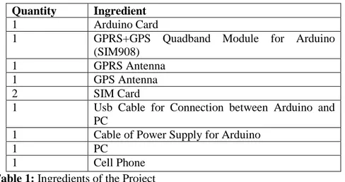
Quantity Ingredient
1 Arduino Card
1 GPRS+GPS Quadband Module for Arduino
(SIM908)
1 GPRS Antenna
1 GPS Antenna
2 SIM Card
1 Usb Cable for Connection between Arduino and PC
1 Cable of Power Supply for Arduino
1 PC
1 Cell Phone
Table 1: Ingredients of the Project
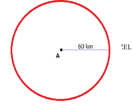
List of the equipments used for this Project is shown on the Table 1. Before explaining, the steps of the Project the flowchart logic of the GPS are detailed. Let us assume that that a person got lost in a location. Other person said that he saw the lost person 60 kilometers from away from city ‘A’. According to this knowledge, the person can be on a point that 60 kilometers away from the city ‘A’ shown as the circle in Figure 1.
Figure 1: Points of 60 kilometers away from city A
Another person said that the lost person might be 80 away from the city ‘B’. In this situation the person can be on one point of intersect points of the circles, as illustrated in Figure 2.
Figure 2: Points of 60 kilometers away from city A and 80 kilometers away
from city B
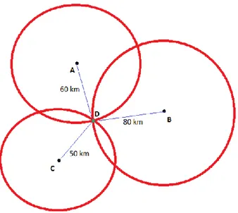
Finally, another person said that the lost person was 50 kilometers away from the city ‘C’. Gathering this information allows us to estimate that the lost person can be on the only point ‘D’ as illustrated in Figure 3.
Figure 3: Point D of 60 kilometers away from city A, 80 kilometers away
from city B and 50 kilometers away from city C
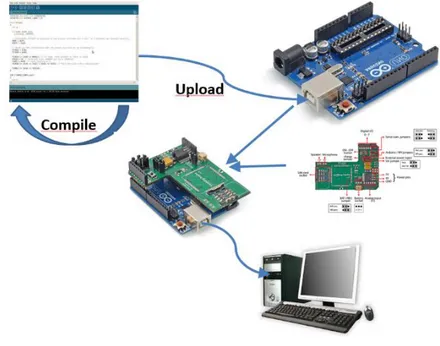
The working procedure of GPS systems is detailed as the above scenario. Namely, GPS determines the location when it links up at least three GPS satellites. Afterwards, the steps of the proposed system are shown in Figure 4.
Firstly, as shown in Figure 4, the receiver circuit reads the coordinates from GPS. Here, an integrated system, including an Arduino card and one SIM908 shield are used as the receiver. After the receiver circuit reads the coordinates, the embedded software in the circuit is executed. Afterwards, the data of location is sent to a PHP web page using GPRS and the location of the receiver is estimated and shown on the Google Maps. On the other hand, for the location of the receiver, a geofencing limit is determined. If this limit is achieved, the receiver will send an SMS to a cell phone using GSM in order to inform the user. The integrated circuit used as receiver includes a software. This software is implemented for the Arduino Card. The steps of the creation of the integrated circuit, uploading the code and its execution are illustrated in Figure 5.
Figure 5: Preparation Flowchart of the Receiver Circuit
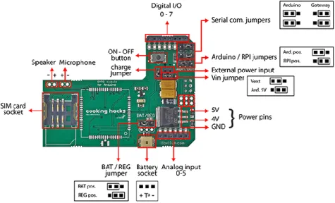
Firstly, the SIM908 shield is illustrated in Figure 6. Here, elements of the shield have more than one possible placement on the circuit as it is shown in the corresponding figure.
Figure 6: SIM908 module connector side
Because the shield will be connected with an Arduino card, Arduino/RPI jumpers are placed with respect to the Arduino’s position. If connection of the Arduino/RPI jumpers is wrong, the shield can be damaged [4].Become with integration of shield and Arduino card, combined circuit can supply the power from a PC or a battery connected with Arduino.In this Project, the power is supplied from Arduino card and because of this Serial com., jumpers are placed with respect to the position of Arduino card. Accordingly, Vin jumper is Ard. 5V position, BAT/REG jumper is at Reg position and charge jumper is removed from the shield. Finally, the sim card is placed into the sim card socket. The pin code of the sim card is identified before via a telephone. This step is done and the pin code is determined as “3344”.
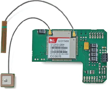
The GPS antenna is placed on GPS u.fl connector and the GPRS antenna is placed on GPRS u.fl connector, as illustrated in Figure 7.
Figure 7: SIM908 module chip side
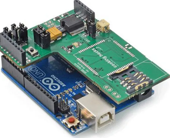
Now the shield is ready for integration. However, before the integration, the code should be uploaded to the Arduino card. To upload the code, including AT commands and copied to Arduino editor, a USB cable is used to connect the Arduino card with PC. When the USB connection is done, the used PC serial port is added to “Serial Port” list in “Tools” menu of editor and this port should be selected from list.Now the code is tested if it is true or not. “Verify” button in shortcuts, which compiles the code, is clicked and if “Done Compiling” is shown, it means that the code is compiled successfully.With clicking the “Upload” button, the code is uploaded to Arduino card and if “Done Uploading” is shown, it means that the code is uploaded to card successfully.After these operations, the integration of shield and Arduino card can be installed and configured successfully as shown in Figure 8.
Figure 8: Integrated Circuit
By means of placing legs to corresponding female sockets, the shield and Arduino card integration are completed. When it is finished successfully, the green led is lighted.A serial port terminal should be used for monitoring to processing of the Arduino code and doing some configuration settings. This can be “Hyperterminal” (for Windows Operating System) or “Arduino IDE Serial Monitor” that can be accessed from Arduino editor too. Because of easy accessing, the second one “Serial Monitor” is preferred. This is opened with clicking on the right top button “Serial Monitor” on the screen [3].
On Serial Monitor screen, baud value is chosen as optimum value “115200” from the right bottom list. Also this value is indicated in the code. Because of using the “Serial Monitor”, “Both NL and CR” option that supplies to send AT commands should be chosen. When these configuration settings are completed, outputs of the code are shown on the Serial Monitor. If the “Restart” button is pushed on the Arduino card the code is restarted with the last configuration settings. The code, after some global variables are initialized, firstly starts with setup() function. When this function is completed, loop() function is processed and the code is finished. get_GPS() function is called for receiving information from GPS and later sendHTTP() function is called in the loop() function. With this function the information that are received from GPS via get_GPS() function are sent to web server (in this step using the GPRS). These information are used for showing the location in the PHP code. Before all of the showing, distance from the center
point is calculated and when the geofencing limit is achieved, the warning message is sent to cell phone.
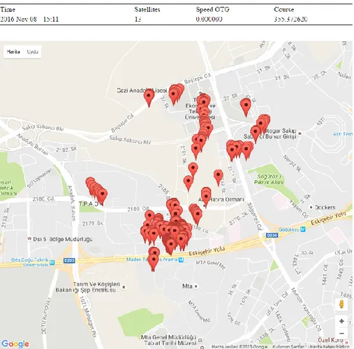
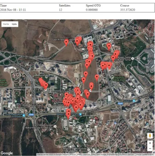
Latitude, longitude, altitude, date, satellites, speedOTG, course data are sent to the web server. When the geofencing limit is achieved, the message is send that includes the information about the achieved geofencing limit and the URL link of the web site, showing the location on the Google Maps. On the other hand, PHP codes are typed in “demo_sim908.php” that is placed in “www” folder is that is placed in the wamp server installation folder. For using Jquery commands in the PHP, “jquery-1.10.1.min.js” called as Jquery library is added in the same directory with the PHP file. Within PHP code, the information, received from GPS is added into a text file and they are read from same file and used to show location on the map. As a result, the corresponding code “http://localhost/demo_sim908.php” is called in a browser installed on a PC that includes an Apache server that shows the real time location of required places using Google Maps (as seen in Figures 9 and 10).
Figure 10: Showing the location on the Google Maps as satellite format.
3. RESULTS AND DISCUSSIONS
There are many GPS receiver devices using for real-time geolocation tracking. Because of the SIM908 shield contains GPS, GRPS and GSM, it is used as the receiver. For processing the data received from GPS, showing location on the web via map, supplying power and connection to a PC, an Arduino card is used. We saw if the configuration settings are done deficiently, the receiver does not work. In fact, all of settings are parts
of a method for receiving data from GPS. The Arduino card is a tool for analyzing the data and communication of a PC, so it presents an user interface. On the other hand, we tried to process the integration circuit on different air conditions and saw changing time for fixing GPS and receiving data. Even the time is limited, if the GPS and GPRS antennas see to air directly. As it is seen, real-time tracking requires several parameters. If these factors considered and the system is redeveloped according to these paramaters. The result will be better than the current study. In addition to these, results reveal that the proposed circuit does not estimate the perfect results that generate some error and tolerance, what is the tolerance depends on? We discuss the differences from the true values for the location and the values taken from the circuit.
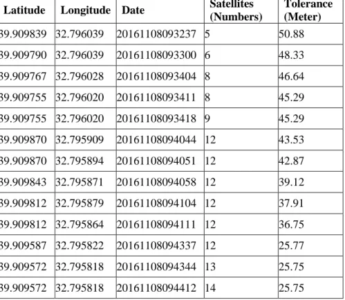
The true coordinate values for a test location is shown as follows:
Latitude: 39.9096142, Longitude: 32.7955208 Latitude Longitude Date Satellites
(Numbers) Tolerance (Meter) 39.909839 32.796039 20161108093237 5 50.88 39.909790 32.796039 20161108093300 6 48.33 39.909767 32.796028 20161108093404 8 46.64 39.909755 32.796020 20161108093411 8 45.29 39.909755 32.796020 20161108093418 9 45.29 39.909870 32.795909 20161108094044 12 43.53 39.909870 32.795894 20161108094051 12 42.87 39.909843 32.795871 20161108094058 12 39.12 39.909812 32.795879 20161108094104 12 37.91 39.909812 32.795864 20161108094111 12 36.75 39.909587 32.795822 20161108094337 12 25.77 39.909572 32.795818 20161108094344 13 25.75 39.909572 32.795818 20161108094412 14 25.75
As shown in Table 2, the coordinate values are changed depending on the time. The important parameters should be taken from the device are latitude and longitude. In fact, one more parameter is very important as well which the number of satellites connected by the proposed device. For determining exact location, it is necessary that the device is linked up with at least 3 satellites. Table 2 proves that if the satellite numbers increase estimated coordinate values will approach to the exact value gradually. However, the satellites includes the numbers 8, 9 and 12 breaks the judgement and can be considered as exceptions. For 8 and 9, the tolerance is steady. Furthermore, linking up with 12 satellites decreases the overall fault tolerance with respect to the time.
Figure 11: The changes of coordinate values taken from the device
Figure 11 is illustrated using the data displayed in Table 2 that shows us the corresponding relation as aforementioned. The tracking system was developed with trial and error approach. For instance, in this system, the integrated circuit originally supplies power from PC via Arduino card. Geofencing was added into the system manually. Because the system does not have any components about geofencing. Therefore, these developments can be updated depending on the necessities of which purpose of the device is used. 0 10 20 30 40 50 60 5 6 8 8 9 12 12 12 12 12 12 13 14 D istan ce f ro m O ri gi n al Posi ti o n ( me te r)
Linked up Satellite Number Original Position: Latitude: 39.9096142, Longitude: 32.7955208
REFERENCES
[1] Hernández Pajares, M., José Miguel Juan Zornoza, Jaime Sanz Subirana, GPS Data Processing: Code and Phase : Algorithms, Techniques and Recipes, Centre de Publicacions del Campus Nord, UPC, 2005.
[2] Shanghai SIMCom Wireless Solutions Ltd., SIM908_AT Command Manual_V1.02, 2011.
[3] Margolis, Michael, Arduino Cookbook, 2011.
[4] www.cooking-hack.com, web site:
“http://www.cooking-hacks.com/documentation/tutorials/geolocation -tracker-gprs-gps-geoposition-sim908-arduino-raspberry-pi”
[5] http://m2msupport.net/ web site: “http://m2msup port.net/m2msupport/gps-data-on-m2m-modules/”
[6] Monti, G., Corchia, L., De Benedetto, E., & Tarricone, L., Wearable logo-antenna for GPS-GSM-based tracking systems. IET Microwaves, Antennas & Propagation, 1332-1338. (2016).
[7] Beeco, J., & Hallo, J., GPS Tracking of Visitor Use: Factors Influencing Visitor Spatial Behavior on a Complex Trail System. Journal of Park & Recreation Administration Summer, 43-61. (2014). [8] Larraz Giménez, V., & Fantova Puyalto, E., Using GPS devices to track
herds of grazing sheep. Albéitar (175) Zaragoza: Grupo Asis Biomedia, S.L., 6-7, (2014).