EVALUATION OF REINFORCING BARS RATIO EFFECTS ON
SCC BEAM-COLUMN JOINT PERFORMANCE
Hamid FARROKH GHATTE
*Received: 05.07.2019; revised: 05.09.2019; accepted: 21.09.2019
Abstract: Beam-column joints require a high ductility during the unexpected loadings that necessitate the
need for ductile concrete in such unprotected locations. Alternatively, self-compacting concrete (SCC) is a sort of concrete which has generated tremendous interest throughout the last decades in order to reach a ductile structural elements during the seismic actions. Specific properties of this type of concrete include high performance, high resistance against segregation and needless to internal or external vibration in order to compact. In the seismic regions, ductility is one of the most important factors in the design of reinforced concrete (RC) members, especially structural joints flexural performance; it is due to the enhance in the capability of plastic deformability. This paper describes load-displacement behavior of experimental and theoretical analysis of four SCC beam-column joints with different percentage of the ratio of the reinforcing bars (ρ). In the theoretical phase of this investigation three-dimensional nonlinear finite element method (FEM) model i.e., Seismostruct was used and the load-deflection diagrams were plotted to compare the test results with the numerical output. The experimental results and nonlinear FEM modeling indicate that using SCC as a workable concrete in beam-column joints of reinforced concrete structures has satisfactory performance in terms of ductility and energy dissipations.
Keywords: Beam-column joint, Ductility, FEM, Load-deflection, Self-compacting concrete
Kendiliğinden Yerleşen Betonla Yapılan Kolon-Kiriş Birleşimlerinde Donatı Oranı Etkisinin Değerlendirilmesi
Öz: Yüksek süneklik gerektiren kolon-kiriş düğüm noktaları gibi korunmasız bölgelerde, beklenmedik yüklemeler altında, sünek betona ihtiyaç duyulmaktadır. Alternatif olarak, kendiliğinden yerleşen beton (KYB), deprem etkisi altinda elemanların daha sünek davranış gösteren bir yapıya ulaşmak için son yıllarda büyük ilgi yaratan bir beton türüdür. Bu tipteki betonların belirgin özellikleri yüksek performans, segregasyona karşı yüksek direnç ve yerleşme için iç veya dış vibrasyona ihtiyaç duyulmamasıdır. Deprem bölgelerinde, süneklik, özellikle eğilmeye maruz kalan yapısal bağlantı noktalarının performansında önemli bir faktördür ve bu davranış plastik yerdeğiştirme kapasitesindeki artıştan kaynaklanmaktadır. Bu makalede, KYB kullanılan ve farklı donatı oranlarındaki dört adet kolon-kiriş düğüm noktasının yük-yerdeğiştirme davranışının deneysel ve teorik analizleri açıklanmaktadır. Bu araştırmanın teorik aşamasında, üç boyutlu sonlu elemanlar metodu (SEM), Seismostruct doğrusal olmayan yazılımı kullanılarak, deneysel-nümerik sonuçlar karşılaştırılmış ve yük-yerdeğiştirme diyagramları çizdirilmiştir. Deneysel sonuçlar ve doğrusal olmayan SEM modeli, kolon-kiriş düğüm noktalarında işlenebilir beton olarak KYB’un kullanımının, betonarme yapılarda süneklik ve enerji yutma kapasitesi bakımından tatmin edici bir performansa sahip olduğunu göstermiştir.
Anahtar Kelimeler: Kolon- Kiriş düğüm noktası, SEM, Yük-yerdeğiştirme, Kendiliğinden yerleşen
beton, İşlenebilir beton
*
Antalya Bilim University, Faculty of Engineering, Civil Engineering Department, 07190, Antalya, Turkey. Corresponding Author: Hamid FARROKH GHATTE ([email protected] & [email protected])
1. INTRODUCTION
Self-compacting concrete (SCC) has found a great application in reinforced concrete (RC) members during the last decades. Based on merit high filling ability and excellent anti-segregation before hardening while good mechanical properties can also be achieved after hardening of concrete. However, the requirements of high volume binder and sand-to-aggregate ratio in SCC may lead to reducing in terms of the modulus of elasticity of this type of concrete as well as the anchoring strength between the concrete and surrounding steel bars. If the mixer of SCC is not reasonably optimized, the mechanical properties of SCC structures may not be satisfying. The mechanical properties of SCC have been widely investigated (
Tsonos
et al. 1993; Persson et al. 2001; Domone 2006; De Almeida et al. 2008; Valcuende et al. 2009; Desnerck et al. 2010). In terms of bond properties between rebars and SCC, an investigation was coordinated by Soleymani et al. (2013), and the results were mentioned that the bond performance of SCC is superior. The performance of structural RC members prepared with SCC has also investigated in accordance with both flexural and shear monotonic loads. (Sonebi et al. 2003; Lachemi et al. 2005; Hassan et al. 2008; Kim et al. 2010;Bedirhanoglu
et al. 2010; Soleymani et al. 2014; Dashti et al. 2017; Dhakal et al. 2018). In the case of beams made with SCC, Hassan et al. (2008) coordinated an investigation and reported that when the ratio of longitudinal bars in the beam decreased the reduction in shear capacity is significantly noticeable. An investigation presented by Kim et al. (2010) reported the mechanical properties like the influence of the aggregate size of high-strength concrete (by 70 MPa compressive strength). The results mentioned the aggregate interlock contribution in the shear capacity of high-strength concrete. In the case of numerical investigations, some studies are in the literature that reported success in simulating highly nonlinear problems also vital models for concrete and steel (Li B et al. 2009 and Dashti et al.2017).When a self-compacting reinforced concrete structure is subjected to an earthquake or to loading, its ability to deform inelastically is of importance together with its ability to carry the load. The assumed redistribution of internal moments and shears is dependent on the adequate development of plastic rotations with the resulting maximum energy-absorption capacity.
The results of the above-mentioned studies showed the importance of investigation of flexural behavior of reinforced SCC both experimentally and theoretically. The significance of this research lies to obtain a better understanding of the load-deformation performance of reinforced self-compacting concrete beam-column joints loaded to failure in terms of ductility and energy dissipation during the seismic actions. Furthermore, this work has enhanced our knowledge around the factors contributing to the ductility of beam-column connections particularly amount of reinforcing ratio not only on tension but also in compression in reinforced self-compacting concrete structures; that is, their ability to deform in the inelastic range beyond yielding, commonly referred to as “plastic hinging”. In the experimental part, four nearly full-scale reinforced SCC connections were studied in terms of bending with different amount of reinforcing details without axial load, utilizing simple beams loaded at mid-span through a stub to simulate a beam-column joint. In the analytical section of the study, an inelastic behavior of the specimens was determined by employing the realistic material models using Seismostruct (2013) as a three-dimensional finite element method (FEM) modeling nonlinear software.
2. EXPERIMENTAL PROGRAM
A total number of four reinforced beams-column joints were cast and tested based on one point load using SCC with the presented specification in Fig. 1. General view of the specimens, reinforcement details, and dimensions of the specimens are represented in Figs. 1 and 2. The
specifications of reinforcing bars, test matrix and general specification of the specimens are presented in Tables 1 and 2.
2.1 Test Specimens and Material Properties
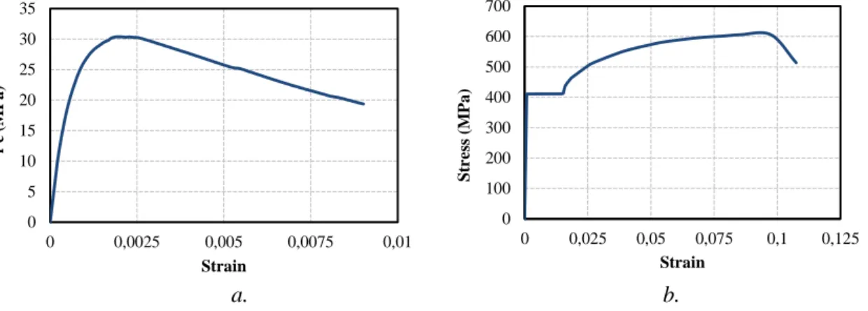
The specimens are representative of a beam-column connection in RC structures. The cross-section dimensions of all tested specimens were 150 mm x 300 mm. Stress-strain relationships of concrete (at 28 days), and reinforcing bars (longitudinal and transverse) are given in Fig. 3. Based on Fig. 3a, the compressive strength of concrete (fc) was around 30 MPa (tests were on standard cylinders of 150 mm x 300 mm dimensions). In the case of curing of the concrete, polyethylene sheets used for 28 days. Table 2 summarizes the basic specifications of reinforcements. In Table 2, fsy, fsmax and fsu are the yield, maximum and ultimate tensile stresses, whereas εsy, εsmax, and εsu are the axial tensile strains corresponding to these stresses, respectively. The clear cover was 25 mm over the transverse reinforcement. All specimens were constructed by using 90° hooked stirrups with a spacing of 150 mm throughout of the beam. The specimens consistes of tow parts, beam and stub (as a part of column) for applying the loads.
Figure 1:
Section A-A Section B-B
Figure 2:
Reinforcement details (all dimensions are in cm)
a. b.
Figure 3:
a. Concrete stress-strain relationship b. Longitudinal reinforcement stress-strain
relationship
Table 1. Mechanical features of the reinforcing bars
f sy (MPa) εsy fsmax (MPa) εsmax fsu (MPa) εsu
410 0.002 605.6 0.009 513 0.107
Table 2: Details of the specimens
0 5 10 15 20 25 30 35 0 0,0025 0,005 0,0075 0,01 f' c (M Pa ) Strain 0 100 200 300 400 500 600 700 0 0,025 0,05 0,075 0,1 0,125 S tr ess (M Pa ) Strain As /b As d (mm) d (mm) fc (MPa) Beam No. 1.61 2Φ20 0.33 1.61 2Φ20 3.8 25.8 28.0 S3 1.04 2 Φ16 0.38 1.61 2Φ20 3.6 25.8 30.8 S4 1.31 2Φ18 0.56 2.52 2Φ25 3.9 25.8 32.7 S5 1.61 2 Φ20 0.66 3.20 2Φ28 4.0 25.6 30.7 S6
2.2 Test Setup
A simply supported condition setup used for all of the specimens with one-point loads, as printed in Figs. 2 and 3. The clear span of tested beams (distance between the two supported) was kept constant by 2700 mm for all of the tests. The point loads were utilized in 18 to 26 step increments up to the fail by employing a 1450 kN hydraulic jack. A
load cell and electrical
resistance strain gauges were collected and stored by a data logger.
Fig. 2.
During the test, the vertical deflection of mid-span was measured by linear variable differential transformers (LVDT) up to failure. At the end of each step, observations, measurements, crack developments and their propagations on the beam surfaces were recorded. Fig. 4 shows the damage photographs taken at the end of the tests.3. EVALUATION OF TEST RESULTS
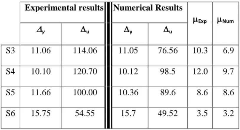
In Fig. 5 experimental load-deflection curves are presented for all of the specimens. Table 3 presents the yield deflection corresponding to the yielding of the longitudinal reinforcements in tension, y, and the ultimate deflection,u. Generally, u improves as ρ diminishes and by improving ρ’ in the section, u will diminish. It is evident that y increases as increases and it will be decreased as ρ’ increases in the section. In the case of ductility performance,
displacement ductility has been defined as a ratio of deflection at the ultimate condition to a deflection at initial yielding of tensile reinforcement. In addition, the ultimate load has been considered as the maximum amount of load that applied to the beam during the test. These are defined and shown in Table 3 and 4. Where Exp andNumare the displacement ductility ratios (= u /y) for the experimental results and numerical output respectively. Displacement ductility ratios of the tested specimens (Experimental results and numerical output) expressed the efficiency of the reinforcement ratio where by the increasing of displacement ductility
was decreased noticeably.
c. d.
Figure 4:
Crack propagations and failure of the specimens
a. S3 Specimen, b. S4 Specimen, c. S5 Specimen and d. S6 Specimen
Table 3: Displacement ductility ratios of the tested specimens (Experimental results and numerical output). All units of displacements are in mm
Experimental results Numerical Results
Exp Num y u y u S3 11.06 114.06 11.05 76.56 10.3 6.9 S4 10.10 120.70 10.12 98.5 12.0 9.7 S5 11.66 100.00 10.36 89.6 8.6 8.6 S6 15.75 54.55 15.7 49.52 3.5 3.2
Table 4: Yielding and ultimate loads of the tested specimens (Experimental results and numerical output) S3 S4 S5 S6 Experimental Load Py (kN) 82.6 84.6 131.8 188.5 Pu (kN) 96.6 118.5 138.5 178.7 Numerical Load Py (kN) 82.5 84.8 135.0 196.5 Pu (kN) 103.2 120.8 159.0 201.8
Figure 5:
Load-Deflection relationship of the specimens
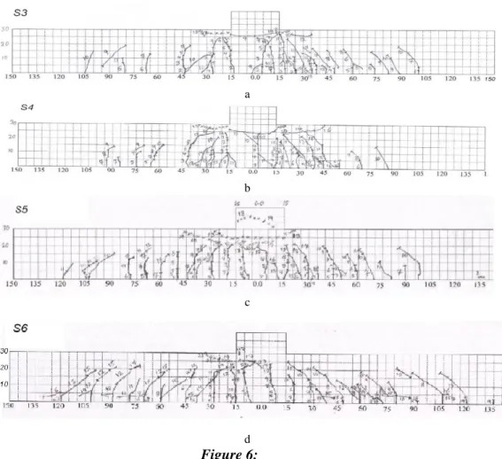
Fig. 6 shows the propagation and variation of measured crack with different widths against applied loads for all tested specimens.
a
b
c
d
Figure 6:
Crack propagation of the specimens; a) S3, b) S4, c) S5 and d) S6 Specimens
Relatively ductile performance was shown by the specimens during the test. Regarding the failure modes of the tested specimens, plastic hinges developed in beams mainly by concrete crushing at the joints. The locations of the plastic hinges were near to the column faces in the joints. The loading process has been continued to failure with large rotation at the plastic
0 25 50 75 100 125 150 175 200 0 25 50 75 100 125 150 Load (k N )
Deflection at the middle of the specimens (mm) S3 S4 S5 S6
hinging zone. The minimum ductility ratio of the specimens was at S6 mainly because of crushing and spalling of concrete in compression.
The determined energy dissipation characteristics based on the test results are compared for different reinforcement ratios in Fig. 7. As seen in this Fig. 7, the energy dissipations determined through the experimental study are mentioned that using reinforcement ratio around 50% of the balanced section amount had the best performance between the specimens in the current study (since S5 has the best performance in terms of energy dissipations among the specimens).
Figure 7:
Comparison of energy dissipation of the specimens
4. ANALYTICAL STUDY
In the analytical part, firstly, all of the specimens were modeled separately using Seismostruct (2013) software as a finite element platform that has been used by Ghatte et al. 2018 for prediction the seismic performance of full-scale reinforced concrete members. Secondly, the results of the modeled specimens have been compared with experimental results with respect to load-deflection curves. In this program, the distributed material nonlinear performance along the member is specifically presented by using a fiber modeling approach. For this purpose, the spreading of the nonlinearity of the material along the length of elements and the cross section area is explicitly presented by using a fiber modeling technique. This program is capable to determine major displacement performance and the failure load of elements accurately not only under static loading but also under dynamic loading. During the process, the program considers the geometric nonlinearities as well as material inelasticity. Inelastic displacement-based formulation of the elements is used in the analyses. Determining a large displacement performance and the collapse loads of members are the specifications of this program under the different loading. In the case of material properties, all materials were defined based on the results of material tests as presented in Fig. 3(a) and (b). For internally confined concrete, Mander et al., (1988) model was used. This model is a uniaxial nonlinear model for constant confinement. A uniaxial constitutive nonlinear hysteretic material model presented by Menegotto and Pinto (1973) has been used for reinforcements. This proposed modeling approach includes the effects of isotropic strain hardening.
Fig. 8 presents the comparisons of numerical output and experimental results for the lateral load-deflection curves. It is clear that the nonlinear analyses executed with the explained assumptions and employed models lead to accurate results with respect to estimating the response of the lateral loads.
0 200 400 600 800 1000 1200 1400 1600
1
E ner gy D is s ipat ion (k J ) S3-S6 Specimens S3 S4 S5 S6There is a negligible difference in the behavior of yielding deflection between the experimental and numerical modeling and a satisfactory difference in ultimate behavior. This can be due to the complex behavior of self-compacting concrete.
a. b.
c. d.
Figure 8:
Theoretical and experimental responses of the specimens
a. S3 Specimen, b. S4 Specimen, c. S5 Specimen and d. S6 Specimen
5. CONCLUSION
The current study presents both experimental and finite element analysis results of four nearly full-scale SCC beams-column joints utilizing simple beams loaded at mid-span through a stub to simulate a beam-column joint.
Considering the loading process to failure by excessive rotation at the location of the plastic hinging with respect to the failure modes, plastic hinges developed at the beams near to the column faces in the joints mainly by concrete crushing under the compression.
The energy dissipations determined through the experimental study are mentioned that using reinforcement ratio around 50% (S5 with ρ/ρb
= 0.56)
of the balanced section had the bestperformance between the specimens in this study.
The finite element modeling adopted by seismostruct showed agreeable compatibility in terms of the behavior of yielding deflection and ultimate condition. Additionally,
in agreement
with analytical calculations, the strengths of the specimens were significantly increased
by increasing the longitudinal reinforcement ratio.
This study brings light to the ductility enhancement and energy dissipation of beam-column joints using SCC as a workable concrete with no need to internal and external vibration, which is a pressing need, particularly during the seismic actions and natural disasters.
0 2 4 6 8 10 12 14 16 0 25 50 75 100 125 150 Load (t on)
Deflection at the middle of S3 (mm) Theoretical Experimental 0 2 4 6 8 10 12 14 16 0 25 50 75 100 125 150 Load (t on)
Deflection at the middle of S4 (mm) Theoretical Experimental 0 5 10 15 20 25 0 25 50 75 100 125 150 Load (t on)
Deflection at the middle of S5 (mm) Experimental Theoretical 0 5 10 15 20 25 0 25 50 75 100 125 150 Load (t on)
Deflection at the middle of S6 (mm) Experimental Theoretical
ACKNOWLEDGMENT
I would like to express my deep and sincere gratitude to my supervisors, Prof. Dr. A.A.Maghsoudi, Civil Eng. Dept. of Kerman University, Kerman, Iran for his detailed and constructive comments, and for his important support throughout this work.
REFERENCES
1. Ashtiani, M. S., Dhakal, R. P., & Scott, A. N. (2013). Post-yield bond behaviour of deformed bars in high-strength self-compacting concrete. Construction and Building Materials, 44, 236-248. doi: 10.1016/j.conbuildmat.2013.02.072
2. Ashtiani, M. S., Dhakal, R. P., & Scott, A. N. (2014). Seismic performance of high-strength self-compacting concrete in reinforced concrete beam-column joints. Journal of Structural Engineering, 140(5), 04014002. doi: 10.1061/(asce)st.1943-541x.0000973
3. Bedirhanoglu, I., Ilki, A., Pujol, S., & Kumbasar, N. (2010). Seismic behavior of joints built with plain bars and low-strength concrete. ACI Struct. J, 107(3), 300-310. doi: 10.1061/(asce)cc.1943-5614.0000156
4. Dashti, F., Dhakal, R. P., & Pampanin, S. (2017). Numerical modeling of rectangular reinforced concrete structural walls. Journal of Structural Engineering, 143(6), 04017031. doi: 10.1061/(ASCE)ST.1943-541X.0001729
5. De Almeida Filho, F. M., Mounir, K., & El Debs, A. L. H. (2008). Bond-slip behavior of self-compacting concrete and vibrated concrete using pull-out and beam tests. Materials and Structures, 41(6), 1073-1089. doi: 10.1617/s11527-007-9307-0
6. Desnerck, P., De Schutter, G., & Taerwe, L. (2010). Bond behaviour of reinforcing bars in self-compacting concrete: experimental determination by using beam tests. Materials and Structures, 43(1), 53-62. doi: 10.1617/s11527-010-9596-6
7. Dhakal, R., & Scott, A. C. N. (2018). Cyclic response analysis of high-strength self-compacting concrete beam-column joints: Numerical modeling and experimental validation. Bulletin of the New Zealand Society for Earthquake Engineering volume 51 issue 1 on pages 23 to 33. doi: 10.5459/bnzsee.51.1.23-33
8. Ghatte, H.F, Comert, M., Demir, C., Akbaba, M., & Ilki, A. (2018). Seismic Retrofit of Full-Scale Substandard Extended Rectangular RC Columns through CFRP Jacketing: Test Results and Design Recommendations. Journal of Composites for Construction, 23(1), 04018071. doi: 10.1061/(ASCE)CC.1943-5614.0000907
9. Hassan, A. A. A., Hossain, K. M. A., & Lachemi, M. (2008). Behavior of full-scale self-consolidating concrete beams in shear. Cement and Concrete Composites, 30(7), 588-596. doi: 10.1016/j.cemconcomp.2008.03.005
10. Kim, Y. H., Hueste, M. B. D., Trejo, D., & Cline, D. B. (2010). Shear characteristics and design for high-strength self-consolidating concrete. Journal of structural engineering, 136(8), 989-1000. doi: 10.1061/(ASCE)ST.1943-541X.0000194
11. Lachemi, M., Hossain, K. M., & Lambros, V. (2005). Shear resistance of self-consolidating concrete beams experimental investigations. Canadian journal of civil engineering, 32(6), 1103-1113. doi: 10.1139/l05-066
12. Li B, Tran CTN and Pan TC (2009). Experimental and numerical investigations on the seismic behavior of lightly reinforced concrete beam-column joints. ASCE Journal of Structural Engineering, 135(9): 1007-1018. doi: 10.1061/(ASCE)ST.1943-541X.0000040
13. Mander, J. B., Priestley, M. J., & Park, R. (1988). Theoretical stress-strain model for confined concrete. Journal of structural engineering, 114(8), 1804-1826. doi: 10.1061/(ASCE)0733-9445(1988)114:8(1804)
14. Menegotto, M., & Pinto, P. (1973). Method of Analysis for Cyclically Loaded Reinforced Concrete Plane Frames Including Changes in Geometry and Non-elastic Behavior of Elements under Combined Normal Force and Bending. Proceedings. IABSE Symposium on Resistance and Ultimate Deformability of Structures Acted on by Well-Defined Repeated Loads, International Association of Bridge and Structural Engineering, 13, pp. 15-22. Lisbon, Portugal.
15. Persson, B. (2001). A comparison between mechanical properties of self-compacting concrete and the corresponding properties of normal concrete. Cement and concrete Research, 31(2), 193-198. doi: 10.1016/S0008-8846(00)00497-X
16. SeismoStruct v6.5. (2013). A computer program for static and dynamic nonlinear analyses of framed structures. Available from http://www.seismosoft.com
17. Sonebi, M., Tamimi, A. K., & Bartos, P. J. (2003). Performance and cracking behavior of reinforced beams cast with self-consolidating concrete. Materials Journal, 100(6), 492-500. doi: 10.14359/12956
18. Tsonos, A. G., Tegos, I. A., & Penelis, G. G. (1993). Seismic resistance of type 2 exterior beam-column joints reinforced with inclined bars. Structural Journal, 89(1), 3-12. doi: 10.14359/1278
19. Valcuende, M., & Parra, C. (2009). Bond behaviour of reinforcement in self-compacting concretes. Construction and Building Materials, 23(1), 162-170. doi: 10.1016/j.conbuildmat.2008.01.007