Corresponding author: Aykan AKAR E-mail: [email protected]
Original Investigation
Published Online: 08.02.2016aykan aKaR, Erdinc CıVELEK, Tufan CanSEVER, Fatih aYDEMıR, Mehmet nur aLTınoRS
Baskent University, School of Medicine, Department of Neurosurgery, Ankara, TurkeyThe Relationship of the Vertebral Artery with Anatomical
Landmarks in the Posterior Craniovertebral Junction of
Fresh Human Cadavers in the Turkish Population
ABSTRACT
arch of the atlas to the spinous process of the axis with a heavy silk thread (20). Since then, other techniques have been developed. These include wire fixation with a midline graft (Gallie-type), wire fixation with two laminar grafts (Brooks-type), transarticular screw fixation (Magerl technique), and bilateral laminar clamps (Halifax technique) (4, 19, 20). The most recent technique involves screw fixation of the lateral mass of C1 with pedicle screws to C2—the so-called Goel technique as modified by Harms(29). The proximity of the VA, spinal cord, and C-2 ganglion and nerve root to the upper cervical spine has confirmed the difficulty of the surgery in this region.
█
INTRODUCTION
The craniovertebral junction and upper cervical spine surgery requires a three-dimensional understanding of the anatomy. Instability in the upper cervical spine can occur when any part of the components are damaged by congenital defects, neo-plasm, inflammation, or trauma including fractures of occipital condyle, atlas, axis and atlantooccipital and atlantoaxial dis-locations.
In 1910, the first description of surgical treatment with posterior approach for instability of upper cervical spine appeared in the literature. Mixter et al. reported securing the posterior
AIM: Surgical anatomy concerning the posterior craniovertebral region in fresh human cadavers was studied to provide most accurate information for the surgical approach.
MATERIAL and METHODS: In thirty-two fresh human cadavers, the distance from the posterior tubercle to the sulcus of vertebral artery (VA), the thickness and length of the third segment of VA (V3), the distance of C1/C2 facet to V3, the length, height and shape of the C2 ganglion to the neighboring structures, the distance from medial border of C1 lateral mass to dura mater, the distance of the transverse process of atlas to mastoid tip, the thickness of C1 posterior arcus were measured.
RESULTS: There were variations of sulcus of VA in 14 of 32 cadavers (43.7%), the right VA was larger in 23 cadavers (71.8%). The ganglion was found over the C1 lateral mass screw entry point in 45 of 64 ganglions (70.31%) and below the screw entry point in 19 of 64 ganglions (29.69%). The distance of the medial border of the C1 lateral mass to dural tube was 3.81±0.55 mm at the right side and 3.91±0.59 mm at the left. The thickness of C1 posterior arch was 3.73±0.75 mm at the right side and 3.75±0.77 mm at the left. The mean distance from the transverse process of C1 to the mastoid tip was 15.82±4.49 mm at the right side and 15.46±4.38 mm at the left.
CONCLUSION: This is the most comprehensive and only fresh cadaver study about this region in the literature. KEywORDS: Anatomical landmark, Craniovertebral junction, Vertebral artery
There are many important structures in this region. The current study which was performed in fresh human cadavers evaluates the morphometric characteristics of these important structures and landmarks.
█
MATERIAL and METHODS
This study was performed in the Center of Forensic Medicine. Thirty-two cadavers’ aged 18 to 65 years (mean age 43 years, 21 men and 11 women) were used. The cadavers were fresh cadavers chosen in postmortem 12 to 24 hours. Exclusion criteria in chosen cadavers were having neck trauma, gross evidence of congenital or acquired vertebral pathology and previous cervical operation. All dissections were performed by a single neurosurgeon in a private autopsy training room. A digital camera (Sony, 5.1 megapixels), and some necessary tools (tripod and light power) were placed to most proper place to take high-quality pictures during dissections.
Surgical Dissection
The cadavers were placed on the autopsy table in prone posi-tion. For each dissection, we approximated true intraopera-tive positioning by placing the head of the cadaver in flexed position. The chest was supported with 10 cm height of pad. Instead of a standard linear skin incision beginning at the level of the inion, the routine bicoronal skin incision used in autop-sy procedure was lengthened over the mastoid region until the level of the prominence of C7 spinous process (Figure 1). All symmetric structures were measured bilaterally and were used electronic digital calipers and a standard rule accurate to 0.01 mm.
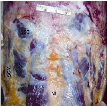
using microsurgical instruments, dissection was carried out from the skin up to the VA, dural tube and C2 ganglion, in layers. The most superficial muscle layer was composed of the trapezius, splenius capitis and semispinalis capitis muscles (Figure 2). We reflected the trapezius and splenius capitis medially, and identified the longissimus capitis and inferiorly the transverse process of Cl, one of the most important bony landmarks for VA identification (Figure 3). Muscle dissection proceeded with the goal of locating the suboccipital triangle composed of the superior and inferior oblique muscles, and the rectus capitis major muscle (Figure 3). Once it was found, we opened this triangle to reveal the VA between C1 and the occiput. Small tributaries from internal vertebral plexus and small muscular veins in the suboccipital triangle form a rich venous plexus around the VA (Figure 3). The spinous process of the 3rd cervical vertebra, the axis and the posterior arch of
the atlas were then visualized. The transverse process of C1 was identified along with the attachment of the superior and inferior oblique muscles (Figure 3). The suboccipital muscles were then removed and the entire posterior arch of the C1 was dissected subperiosteally up to the transverse processes on either side. The VA and suboccipital nerve was then dissected and VA was followed up to its dural entry point (Figures 4, 5). The bony landmarks were defined and digital photographs were taken. The course, relationships and the branches of the VA were studied and measurements were taken (Figure 6). The C2 ganglion and the spinal nerve were preserved in
their anatomic position (Figure 4) and the measurements of C2 ganglion were performed (Figures 6, 7). After removing the posterior arch of C1, the distance of the medial part of lateral mass to the dural tube was measured (Figure 8).
Figure 1: Skin incision used in dissections.
Figure 2: The superficial muscle layer photograph of a cadaveric specimen (NL: Nuchal ligament, SCM: sternocleidomastoid muscle, SC: splenius capitus muscle, SSC: semispinalis capitus muscle).
Figure 3: A photograph of a cadaveric specimen (white-thick dashed line: midline, RCMi: Rectus capitis minor muscle, RCMa: Rectus capitis major muscle, pt: posterior tubercle, Sp: spinous process of C2, OCI: inferior oblique capitis muscle, OCS: superior oblique capitis muscle, white-dashed triangle: suboccipital triangle, single asterisks: Dorsal rami of C2 root, double asterisks: vertebral artery, tp: transverse process of C1, mp: mastoid process, l: distance from transverse process of C1 to mastoid process).
Figure 4: A photograph of a cadaveric specimen (white-thick dashed line: midline, Oc: occipital bone, aom: atlantooccipital membrane, MS: medulla spinalis, C2g: C2 ganglion, single asterisks: Ventral rami of C2 root, double asterisks: Dorsal rami of C2 root, Va2: second segment of vertebral artery, Va3: third segment of vertebral artery, tp: transverse process of C1, k: the length of third segment of VA).
Figure 5: A photograph of a cadaveric specimen (white-thick dashed line: midline, va: vertebral artery, black arrow: suboccipital nerve, single asterisks: complete canal of vertebral artery sulcus).
Figure 6: A photograph of a cadaveric specimen (white-thick dashed line: midline, Oc: occipital bone, va: vertebral artery, C2g: C2 ganglion, single asterisks: medial border of vertebral artery sulcus, double asterisks: C2/C3 facet joint, g: the distance of medial border of C2 ganglion to midpoint of the dural tube, h: the distance of posterior tubercle of atlas to medial border of sulcus of vertebral artery, i: thickness of third segment of vertebral artery, j: the distance of C2 ganglion to midpoint of C2-C3 facet joint).
Measured Landmarks and Structures
For each dissection, we recorded the following measurements: 1) the distance of tubercule of atlas to medial border of VA navigating within sulcus, 2) the calibration of 3rd segment of
VA, 3) the length of 3rd segment of VA, 4) the distance of C1-C2
facet joint to 3rd segment of VA, 5) the height of C2 ganglion, 6)
the length of C2 ganglion, 7) the distance of superior border of C2 ganglion to inferior border of posterior arcus of atlas, 8) the distance of inferior border of C2 ganglion to superior border of the lamina of axis, 9) the distance of superior border of C2 ganglion to 3rd segment of VA, 10) the distance of C2 ganglion
to midpoint of C2-C3 facet joint, 11) the distance of medial border of C2 ganglion to midpoint of the dural tube, 12) the distance from medial border of C1 lateral mass to dural tube, 13) the distance of the tip of the transverse process of Atlas to mastoid tip, 14) the thickness of C1 posterior arcus (so-called pedicle thickness).
The measurements in male and female specimens and the effect of the age on the measurements for each parameter were compared with linear regression test. The values of the right and the left sides were compared with paired sample tests. Statistical significance was set at P<0.05.
█
RESULTS
The details of the measurements were listed in the Table I.
The Sulcus of VA
Variations
In 14 cadavers (43.8%), a variation of VA sulcus in C1 vertebra was seen. In 9 cadavers (28.1 %) there was semi-canal, in 7 (21.9%) there was complete canal (Figure 9). In 2 (6.3%) cadavers bilateral semi-canal, right-sided semi-canal in 4 cadavers (12.5 %), left-sided semi-canal in 1 cadavers (3.1%), right-sided complete canal in 4 cadavers (12.5%), left-sided complete canal in 1 cadavers (3.1%) and in 2 cadavers (6.3%) both semi-canal and complete canal were present. There were variations of sulcus of VA in 10 of 21 male cadavers (47.6 %) and in 4 of 11 female cadavers (36.4%). Complete canal were present in 5 male (23.8%) and in 2 female cadavers (18.2 %).
Localization of suboccipital nerve in VA sulcus
Suboccipital nerve was observed at neighboring of posteroinferior part of the vertebral artery in 32 cadavers, and at posterior part of the VA in 2 cadavers (Figure 9).
VA (third part) (V3)
In all cases, the artery was located in the transverse foramen of C1 and traveled through the suboccipital triangle. The posterior-inferior cerebellar artery did not arise from the VA segment in any specimen.
In 23 cadavers, the right VA was larger than the left one and in 9 cadavers the left side was larger (Table I). The larger side was accepted as the dominant side. In 18 cadavers, the right VA was longer than the left and in 14 cadavers the left side was longer (Table I).
Figure 8: A photograph of a cadaveric specimen (white-thick dashed line: midline, Oc: occipital bone, va: vertebral artery, MS: medulla spinalis, m: the distance from medial border of C1 lateral mass to dural tube, single asterisks: C1/C2 facet).
Figure 7: A photograph of a cadaveric specimen (white-thick dashed line: midline, Oc: occipital bone, va: vertebral artery, C2g: C2 ganglion, sp: spinous process of C2, single asterisks: C1/C2 facet, a: the distance of superior border of C2 ganglion to inferior border of posterior arcus of atlas b: the distance of superior border of C2 ganglion to 3 rd segment of vertebral artery,
c: the distance of inferior border of C2 ganglion to superior border of the lamina of axis, d: the length of C2 ganglion, e: the height of C2 ganglion, f: the distance of C1-C2 facet joint to third segment of vertebral artery).
The distance of inferior border of V3 segment to midpoint of C1-C2 facet joint
In 18 cadavers, the left side was longer than the right and in 14 cadavers the right side was longer (Table I).
C2 Ganglion
The first intervertebral space is not a real foramen as the other cervical levels because it is not limited by any bone structure posteriorly. The C2 ganglion lies with accompanying venous plexus in a large space formed posteriorly by ligamentum flavum. In our observation, at the atlantoaxial interspace the C-2 nerve exited and divided into anterior and posterior rami (Figure 4). The nerve then passed medially and inferiorly to the joint of the C-1 lateral mass. In all dissections the C-2 nerve root ganglion could be retracted downward or upward to expose the lateral mass screw entry zone (Figures 10,11). It was observed that extensive upward or downward moving of the ganglion may cause retraction of the spinal cord and this may cause spinal cord injury.
Shapes
The C2 ganglions were classified in three groups with respect to their shapes(3):
1. Spherical ganglion: The difference between height and the horizontal length of the ganglion was <1 mm.
2. Oval ganglion: The difference between height and the horizontal length of the ganglion was 1–2.5 mm.
Figure 9: A photograph of a cadaveric specimen (white-thick dashed line: midline, Oc: occipital bone, va: vertebral artery, C2g: C2 ganglion, ns: suboccipital nerve, single asterisks: semi-canal for vertebral artery, noma: major occipital nerve, black arrow: dorsal rami of C3 spinal nerve, double asterisks: branch to C3 spinal nerve).
Table I: The Measurements (mm) of the Parameters
Male Female Mean
Right Left Right Left Right Left
C1 post. tubercle- VA sulcus MB 18.90±2.48 18.53±2.00 18.00±2.40 18.00±2.06 18.60±2.44 18.25±2.03 V3 calibration 4.63±0.70 4.13±0.35 4.30±0.67 4.46±0.57 4.38±0.77 4.29±0.88 V3 length 19.28±2.36 17.88±1.36 18.98±2.56 19.98±1.96 19.08±2.47 18.66±1.45 C1/C2 facet joint-V3 11.18±1.96 11.48±1.56 11.08±1.76 11.38±1.96 11.04±1.84 11.35±1.87 C2G height 4.88±0.36 4.98±0.56 4.68±0.96 4.90±0.96 4.74±0.89 4.91±0.67 C2G length 5.85±1.01 6.18±1.06 5.78±0.96 6.05±1.16 5.77±1.02 6.06±1.08 C2G SB - C1 post. arcus IB 2.18±1.06 1.85±1.11 1.98±1.56 1.99±0.96 2.00±1.42 1.95±1.29 C2G IB - C2 lamina SB 3.68±1.86 3.50±1.61 3.65±1.96 3.45±1.65 3.62±1.95 3.48±1.60 C2G SB - V3 7.58±1.86 7.61±1.58 7.40±1.76 7.60±1.65 7.42±1.83 7.60±1.57 C2G-C2/C3 facet joint MP 16.73±2.86 16.31±2.58 16.68±2.97 16.28±2.83 16.71±2.94 16.27±2.79 C2G- dural tube MP 13.20±4.16 12.39±3.49 13.20±3.97 12.28±3.53 13.16±4.21 12.36±3.49 C1 lateral mass-dural tube 3.77±0.46 3.89±0.49 3.85±0.67 3.92±0.53 3.81±0.55 3.91±0.59 C1 transverse process tip-
mastoid tip 15.92±4.40 15.55±4.35 15.72±4.50 15.41±4.39 15.82±4.49 15.46±4.38 C1 pedicle thickness 3.80±0.76 3.78±0.79 3.70±0.77 3.72±0.73 3.73±0.75 3.75±0.77 VA: vertebral artery, G: ganglion, V3: third segment of the vertebral artery, MB: medial border, SB: superior border, IB: inferior border, MP: midpoint.
The ganglion was found over the screw entry point in 45 of 64 ganglions (70.31%) and below the screw entry point in 19 of 64 ganglions (29.69%) (11 at the right and 8 at the left) (Figures 10,11). The ganglion was covering bilaterally the screw entry point in 19 cadavers, and it was located below the screw entry point bilaterally in 6 cadavers.
C1 lateral mass screw trajectory
The measurements of distance of the medial border of the C1 lateral mass to dural tube were listed in Table I. The C1 lateral mass screw trajectory is usually 17 degrees medially and 22 degrees cranially.
C1 Posterior Arch Thickness (the thickness of so-called C1 pedicle)
The part of the posterior arch on the vertical line passing through the entry point of the lateral mass screwing was bilaterally determined. The thickness of C1 posterior arch (the distance between superior and inferior borders was measured (Table I). This distance was measured as below 3 mm in 5 cadavers (15.6%), between 3 and 4 mm in 15 cadavers (46.8%), between 4 and 5 mm in 8 cadavers (25%) and above 5 mm in 4 cadavers (12.5%).
The tip of the transverse process of C1 was located anterior, medial, and inferior to the mastoid process. The measurements of distance of the tip of C1 transverse process to the tip of the mastoid process were listed in the Table I.
3. Spindle-like ganglion: The difference between height and the horizontal length of the ganglion was 2.5 mm.
There were 17 spherical, 12 oval and 3 spindle-like ganglion at the right side and 14 spherical, 14 oval and 4 spindle-like ganglion at the left side (Table II). According to this definition, 48.4% (31 of 64) of ganglions were spherical, 40.6% (26 of 64) of ganglions were oval, and 10.9% (7 of 64) of ganglions were spindle-like. The ganglions having oval or spherical shapes could be dissected easily but retraction and dissection of the spindle-like shape having ganglions were difficult.
The localization of the ganglion according to the point of the lateral mass screwing (The midpoint of the inferior part of the lateral mass)
The localization of the ganglion was evaluated by using the lateral mass screwing point which is midpoint of the inferior part of the lateral mass in both mediolateral and cranio-caudal directions. The localizations of the ganglia were described as on, over or below the point.
Table II: Distribution of C2 Ganglion Types
Right Left Total
Spherical ganglion 17 14 31
Oval ganglion 12 14 26
Spindle-like ganglion 3 4 7
Figure 10: A photograph of a cadaveric specimen (white-thick dashed line: midline, Oc: occipital bone, va: vertebral artery, C2g: C2 ganglion, ns: suboccipital nerve, single asterisks: complete canal variation of vertebral artery sulcus, black arrow: semi-canal variation of vertebral artery sulcus, double asterisks: occipital condyle, triple asterisks: lateral mass).
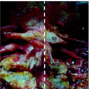
Figure 11: A photograph of a cadaveric specimen (white-thick dashed line: midline, Oc: occipital bone, black arrows: bilateral C2/C3 facet fusion anomaly, plus sign: lateral mass screw inserting point).
(12.5%), left-sided complete canal in 1 cadavers (3.1%) and both semi-canal and complete canal in 2 cadavers (6.3%). The VA, as it lies in the groove along the atlas vertebra, normally glides easily with neck movements. If this movement of the artery is restricted, intimal damage may occur leading to dissection. It was hypothesized that the presence of the arcuate foramen might cause tethering of the VA and lead to its dissection by repetitive trauma(6, 23). In the majority of cases VA occlusion does not cause ischemia, but tends to act as a source of recurrent embolism. A syndrome involving symptoms of headache, retroorbital pain, vasomotor disturbances of the face, and recurrent disturbances of vision, swallowing, and phonation was described and it was hypothesized that these symptoms were due to alternations of the blood flow within the VAs(17). Limousinet al. has reported good results in patients with this syndrome and identified cases in which the foramen arcuale was surgically fractured and a periarterial sympathectomy of the V3 performed. Although the suboccipital nerve also travels with the VA through the foramen arcuale no reported cases of symptomatic entrapment of this nerve at this site have been reported. This may be due to the fact that this nerve primarily innervates the small muscles that form the suboccipital triangle and rarely has a cutaneous branch. Ebraheim et al.suggested that dissection on the posterior aspect of the posterior ring should remain within 12 mm lateral to the midline, and dissection on the superior aspect of the posterior ring should remain within 8 mm of the midline (8). In other studies this distance was varied from 10 mm to 19.7 mm(1, 5, 26, 30). In our study, the mean distance of the VA groove from the midline on the outer cortex was found to be 18.60±2.44 mm. (right side) and 18.25±2.03 mm (left side). These results are greater than the results in the literature(1, 8, 26, 30).
In the previous studies the diameter of VA was varying from 2.3 mm to 7.4 mm(2,5). In our study, the average right VA diameter was 4.38±0.77 mm whereas that for the left VA was 4.29±0.88 mm. The larger side was accepted as the dominant side. In 23 cadavers, the right VA was larger than the left one and in 9 cadavers the left side was larger.
Cacciola et al.found the length between exit point of the VA from C1 transverse foramen to dural entry point as 32.3 mm to 43.5 mm (average 35.7 mm) (5). In our study, in 18 cadavers, the right VA was longer than the left and in 14 cadavers the left side was longer. Our results are smaller than the results presented in the study performed by Cacciola et al.
Hong et al. found anatomical variations (fenestrated VA, anomalous origin of the PICA) of the V3 in 55 cases (5.4%) in CT angiography. In our study, we did not detect these types of abnormal courses of VA (12).
The transverse process of the atlas is easily felt as the single bony prominence between the mastoid process and the angle of the jaw. Reports in the literature state that the transverse process of C1 is located approximately 15-22.5 mm inferior and posteromedial to the mastoid tip similar to our results(2, 7).
In all the quantitative measurements of different parameters, there was no statistically significant difference in the mean values between the right and the left side and no significant differences between the male and female cadavers.
█
DISCUSSION
The atlas has two thick lateral masses and these are connected behind by the long posterior arch (21). In up to 5% of the population, the posterior arch of the atlas is incomplete, and recognition of this condition before surgical exploration is important to avoid a damage of the spinal cord(9). In our study, we did not observe such a variation. Senoglu et al. concluded that most congenital anomalies of the arch of atlas are found incidentally in asymptomatic patients. They also concluded that congenital defects of the posterior arch are more common (3.35%)(28).
The posterior arch of atlas has a groove which accommodates V3 and C1 spinal nerve. The V3 (suboccipital part) extends from the foramen transversarium of the atlas vertebra to its passage through the dura mater at the foramen magnum. Cacciola et al. concluded that the C1 roots course posterior-inferior in relationship to the artery (5). In our study, suboccipital nerve was observed at neighboring of posteroinferior part of the VA in 32 cadavers, and at posterior part of the VA in 2 cadavers.
The arcuate foramen is an anatomical variant of the atlas vertebra: anterior and posterior osseous bridges or ponticles can arch over the VA, to a greater or lesser degree, transforming the arterial groove into a complete or semi-canal. Ponticles are said to occur in 3 to 15% of the population(14). A complete canal was found 1.2% in another study(8). Paraskevas et al. found the presence of a ‘‘canal for the VA’’ (CVA) in 10.23% and an incomplete CVA in 24.43% (23). The complete canal and semi-canal is more common in males (11.11% and 24.9 %) than in females (9.3% and 24.42%). In our study there were variations of sulcus of VA in 10 of 21 male cadavers (47.6%) and in 4 of 11 female cadavers (36.4%). Complete canal were present in 5 male (23.8%) and in 2 female cadavers (18.2%). Radojevic et al. saw the CVA in 3.4% of the cases and incomplete CVA in 1%, while Lamberty et al.saw the CVA in 7.58% of the cases and incomplete CVA in 6.06% (15, 25). Taitz et al.found in the Middle Eastern population an unusually high percentage of atlas bridging (57%) in comparison to other studies (31). If a posterior ponticulus is present, placing the screw too superiorly might cause VA injury.
In a study performed in formalin-fixed cadavers by Tubbs et al., they found that the foramen arcuale may compress the V3. They identified a foramen arcuale in 5% of the cadavers (33). Avci et al. concluded that the artery was completely surrounded by bone at the posterior arch of C1 in 30% of cases (2). In our study, in 14 cadavers (43.8%), a variation of VA sulcus in C1 vertebra was seen. In 9 cadavers (28.1%) there was semi-canal, in 7 (21.9%) there was complete canal. Bilateral semi-canal was present in 2 (6.3%) cadavers, right-sided semi-canal in 4 cadavers (12.5%), left-right-sided semi-canal in 1 cadaver (3.1%), right-sided complete canal in 4 cadavers
cranio-caudal directions. The localizations of the ganglia were described as on, over or below the point. The lateral mass screwing procedure commonly requires caudal retraction of the C2 dorsal root ganglion. Therefore, the localization of the ganglion is clinically important. The ganglion was found over the screw entry point in 45 of 64 ganglions (70.31%) and below the screw entry point in 19 of 64 ganglions (29.69%) (11 at the right and 8 at the left) (Figure 10). The ganglion was covering bilaterally the screw entry point in 19 cadavers, and it was located below the screw entry point bilaterally in 6 cadavers. Stabilization of the upper cervical spine may be required when treating traumatic instability, inflammatory arthropathy, degenerative disease, congenital malformation, and malignancy.
Many techniques were developed by and several variations exist(4, 11, 19). Injury to the VA during placement of a posterior C-1 screw, especially when it occurs on the dominant side, may result in very serious complications. These types of injuries include the formation of an arteriovenous fistula, occlusion, dissection of the VA, and massive bleeding(26). The risk of injury to the VA during placement of screws for atlantoaxial fixation has been calculated to be 4.1% per patient or 2.2% per screw inserted(34). These are considered to be highly associated with screw malpositioning. The risk of neurologic deficit from VA injury was 0.2% per patient or 0.1% per screw, and the mortality rate was 0.1%(34).
In C1 lateral mass screw placement, Goel et al.concluded that the preferred site of screw insertion is the center of the posterior surface of the lateral mass, just above the inferior articular facet of the atlas (10). Tan et al. described the screw fixation via posterior arch and lateral mass in atlas resembling pedicle screw fixation, so-called C1 ‘pedicle screws’. Screws inserted through the posterior arch of C1 into the lateral mass have a longer trajectory compared to lateral mass screws (32). Lee et al. concluded that the average minimal thickness of the posterior-lateral atlas was 3.95 mm. Overall, 85.2% of the 709 mature atlas specimens had a thickness greater than 3 mm, 654 (46.2%) greater than 4 mm, and 194 (13.7%) greater than 5 mm. They estimated that a minimum of 5 mm of bone thickness would be required to safely pass a 3.5-mm screw via the posterior lateral arch, without violating any of the cortical margins(16). Ebraheim et al.measured the thickness of the posterior arch at the thinnest part of groove as 4.1 ± 1.2 mm and Tan et al.measured this parameter as 4.58 ± 0.65 mm (8, 32). In our study, the thickness of C1 posterior arch was 3.73±0.75 mm at the right side and 3.75±0.77 mm at the left. This distance was measured below 3 mm in 5 cadavers (15.6%), between 3 and 4 mm in 15 cadavers (46.8%), between 4 and 5 mm in 8 cadavers (25%) and above 5 mm in 4 cadavers (12.5%).
Seal et al.concluded that the average length of the C1 lateral mass was 16.82±1.00 mm, the average width was 16.06±0.91 mm, and the average height was 15.68±0.98 mm in a study performed in formalin-fixed specimens (27). In dry samples of atlas, Tan et al. found that the transverse diameter of lateral mass and the middle height of lateral mass were 17.52±2.97mm and 13.02 ±1.18 mm (32). The distance of medial border of The axis which has large spinous process plays a principal role
in extending and stabilizing the head and neck. At C-2, there are five muscles: 1) the rectus capitis posterior major muscle; 2) the obliquus capitis inferior muscle; 3) the semispinalis cervicis muscle; 4) the multifidus muscle; and 5) the interspinalis muscle. Together, they act as a dynamic stabilizer for the cervical spine. Several authorshave emphasized the importance of reattaching the removed muscles to the C-2 spinous process as a means of preventing postoperative cervical malalignment (13, 22).
The C2 ganglion lies in the intervertebral space, which is bordered superiorly by the posterior arch of atlas, inferiorly by the lamina of axis, anteriorly by the lateral atlantoaxial joint and its fibrous capsule, and posteriorly by the anterior edge of the ligamentum flavum. The positions of the dorsal root ganglions, the shape and height of the C2 ganglion and its anatomic relations were described in previous studies(3, 18). However, they were not examined in fresh human cadavers previously.
The exploration of the large C-2 ganglion provides a wide exposure of the region. Sectioning of the C-2 ganglion may result in anesthesia in the suboccipital region. Other authors studying this region also agree that sectioning of the C-2 ganglion does not result in any significant disability(10). The retraction of the ganglion for exposure of the region may be more dangerous to the spinal cord than its sectioning. Sectioning of the C2 nerve root does not result in any related symptoms(10, 24).
During dissections and measurements, it was seen that the shape of the ganglions was not always the same. Although they differ individually, the same shaped ganglions were detected bilaterally in the same cadaver. Similar to our findings, Bilge concluded that the different shaped ganglions may be detected in the same cadaver in a study performed in human embalmed cadavers. In respect of its shapes, three types of ganglion (oval, spindle-like, and spherical) were defined as in the study performed by Bilge (3). The shapes of the ganglions were defined as in three types: 70% were oval, 20% were spindle-like, and 10% were spherical. In our study, 48.4% (31 of 64) of ganglions were spherical, 40.6% (26 of 64) of ganglions were oval, and 10.9% (7 of 64) of ganglions were spindle-like. Our observation showed that the ganglions having oval or spherical shapes could be dissected easily but retraction and dissection of the spindle-like shape having ganglions was difficult.
In our study, observations confirmed that the C2 nerve root and ganglion exit from the cord and travel out of the foramen following an almost horizontal course. All C2 ganglia were confined within the C2 foramen between the posterior arch of atlas and the lamina of the axis (Figures 4, 6, 9). Our anatomical dissections showed that the venous plexus can cover the lateral mass and C2 nerve root and ganglion. Intraoperative bleeding from these veins can limit vision to the surgical field, leading to injury of the VA, dural tube and C-2 nerve. In our study, the localization of the ganglion was evaluated by using the lateral mass screwing point which is the midpoint of the inferior part of the lateral mass in both mediolateral and
7. Dowd GC, Zeiller S, Awasthi D: Far lateral transcondylar approach: Dimensional anatomy. Neurosurgery 45:95-99, 1999
8. Ebraheim NA, Rongming X, Muhammad A, Bruce H: The Quantitative anatomy of the vertebral artery groove of the atlas and its relation to the posterior atlantoaxial approach. Spine 23(3):320-323, 1998
9. Gehweiler JA Jr, Daffner RH, Roberts L Jr: Malformations of the atlas vertebra simulating the Jefferson fracture. AJR Am J Roentgenol 140(6):1083-1086, 1983
10. Goel A, Desai KI, Muzumdar DP: Atlantoaxial fixation using plate and screw method: A report of 160 treated patients. Neurosurgery 51:1351-1357, 2002
11. Harms J, Mellcher RP: Posterior C1-2 fuson with polyaxial screw and rod fixation. Spine 26:2467-2471, 2001
12. Hong JT, Lee SW, Son BC, Sung JH, Yang SH, Kim IS, Park CK: Analysis of anatomical variations of bone and vascular structures around the posterior atlantal arch using three dimensional computed tomography angiography. J Neurosurg Spine 8:230-236, 2008
13. Iizuka H, Shimizu T, Tateno K, Toda N, Shimada H, Takagishi K: Extensor musculature of the cervical spine after laminoplasty: Morphologic evaluation by coronal view of the magnetic resonance image. Spine 26: 2220-2226, 2001
14. Köhler H, Zimmer F: Vertebral column. In: Schmidt and Schmidt (eds), Borderlands of normal and early pathological findings in skeletal radiography. New York: Thieme Medical Publishers, 1993
15. Lamberty B, Zivanovic S: The retroarticular vertebral artery ring of the atlas and its significance. Acta Anat (Basel) 85:113-122, 1973
16. Lee MJ, Cassinelli E, Riew KD: The feasibility of inserting atlas lateral mass screws via the posterior arch. Spine 31(24):2798-2801, 2006
17. Limousin CA: Foramen arcuale and syndrome of Barre-Lieou. Its surgical treatment. Int Orthop 4:19-23, 1980
18. Lu J, Ebraheim NA: Anatomic considerations of C2 nerve root ganglion. Spine 23(6):649-652, 1998
19. Magerl F, Seeman PS: Stable posterior fusion of the atlas and axis by transarticular screw fixation. In: Kehr P, Weidner A, (eds), Cervical Spine. Berlin: Springer-Verlag, 1986: 322-327 20. Mixter SJ, Osgood RB: Traumatic lesions of the atlas and axis.
Ann Surg 51:193-207, 1910
21. Naderi S, Cakmakcı H, Acar F, Arman C, Mertol T, Arda MN: Anatomical and computed tomographic analysis of C1 vertebra. Clin Neurol Neurosurg 105:245-248, 2003
22. Nolan JP Jr, Sherk HH: Biomechanical evaluation of the extensor musculature of the cervical spine. Spine 13:9-11,1988
23. Paraskevas G, Papaziogas B, Tsonidis C, Kapetanos G: Gross morphology of the bridges over the vertebral artery groove on the atlas. Surg Radiol Anat 27:129-136, 2005
24. Payer M, Luzi M, Tessitore E: Posterior atlanto-axial fixation with polyaxial C1 lateral mass screws and C2 pars screws. Acta Neurochir 151:223-229, 2009
lateral mass to the dura is clinically important. This measure was not mentioned before in a study in the literature. In our study, the mean value was 3.81±0.55 mm at the right side and 3.91±0.59 mm at the left.
The anatomy of the osseous groove on the superior surface of posterior arch has been studied by various authors; however, the relation of the VA to the C1-C2 facet joint has not been addressed. This distance is important due to close proximity to the C1 lateral mass screw entry point. In our study, the mean distance was 11.04±1.84 mm at the right side and 11.35±1.87 mm at the left. In 18 cadavers, the left side was longer than the right and in 14 cadavers the right side was longer.
In our opinion, the percutaneous ablation of the C2 ganglion in cervicogenic pain and occipital neuralgia may be useful. Therefore, the measurements related to distance of the C2 ganglion to the some landmarks given here are planned to be discussed in another study.
In the posterior approach, detailed anatomical information related to important structures are essential to carry out the operation in more radical manner and in low risk. The current study revealed some surgical landmarks, measurements and, variations for the operations of posterior part of upper cervical spine.
All studies in the literature performed about this subject were conducted upon formalin fixed cadavers or cervical spine that are processed with chemicals. Formalin-fixed techniques render the soft tissue structures, such as ligament, muscle and adipose tissue. Therefore, identification of the structures is more difficult. In contrast to other studies related to this subject, the current study was performed in fresh cadavers; therefore we believe that the data given here are more accurate and helpful for surgery.
█
REFERENCES
1. An HS, Simpson JM: Spinal instrumentation of the cervical spine. In: An HS, Simpson JM (eds), Surgery of the Cervical Spine. London: Martin Dunitz, 1994: 379-400
2. Avci E, Kocaogullar Y, Fossett D: Vertebral artery landmarks for the far-lateral transcondylar approach: An anatomic study. Turk Neurosurg 10:112-117, 2000
3. Bilge O: An Anatomic and morphometric study of C2 nerve root ganglion and its corresponding foramen. Spine 29(5): 495-499, 2004
4. Brooks AL, Jenkins EB: Atlanto-axial arthrodesis by the wedge compression method. J Bone Joint Surg Am 60:279-284, 1978
5. Cacciola F, Phalke U, Goel A: Vertebral artery in relationship to C1-C2 vertebrae: An anatomical study. Neurol India 52(2): 178-184, 2004
6. Cushing KE, Ramesh V, Gardner-Medwin D, Todd NV, Gholkar A, Baxter P, Griffiths PD: Tethering of the vertebral artery in the congenital arcuate foramen of the atlas vertebra: A possible cause of vertebral artery dissection in children. Developmental Medicine & Child Neurology 43:491-496, 2001
30. Stauffer ES: Posterior atlanto-axial arthrodesis: The Gallie and Brooks techniques and their modifications. Techniques in Orthopaedics 9:43-48, 1994
31. Taitz C, Nathan H: Some observations on the posterior and lateral bridge of the atlas. Acta Anat (Basel) 127:212-217, 1986
32. Tan M, Wang H, Wang Y, Zhang G, Yi P, Li Z, Wei H, Yang F: Morphometric evaluation of screw fixation in atlas via posterior arch and lateral mass. Spine 28(9):888-895, 2003 33. Tubbs RS, Johnson P, Shoja MM, Loukas M, Oakes WJ:
Foramen arcuale: Anatomical study and review of the literature. J Neurosurg Spine 6:31-34, 2007
34. Wright NM, Lauryssen C: Vertebral artery injury in C1–2 transarticular screw fixation: Results of a survey of the AANS/ CNS section on disorders of the spine and peripheral nerves. J Neurosurg 88:634-640, 1998
25. Radojevic S, Negovanovic B: La gouttiere et les anneaux osseux de l’artere vertebrale de l’atlas. Acta Anat (Basel) 55:186-194, 1963
26. Rocha R, Safavi-Abbasi S, Reis C, Theodore N, Bambakidis N, De Oliveira E, Sonntag VK, Crawford NR: Working area, safety zones, and angles of approach for posterior C-1 lateral mass screw placement: A quantitative anatomical and morphometric evaluation. J Neurosurg Spine 6:247-254, 2007 27. Seal C, Zarro C, Gelb D,Ludwig S: C1 lateral mass anatomy
proper placement of lateral mass screws. J Spinal Disord Tech 22:516-523, 2009
28. Senoglu M, Safavi-Abbasi S, Theodore N, Bambakidis NC, Crawford NR, Sonntag VKH: The frequency and clinical significance of congenital defects of the posterior and anterior arch of the atlas. J Neurosurg Spine 7:399-402, 2007
29. Sonntag VKH: Lateral mass screw fixation of the atlas: Importance of anatomy of C1 for lateral mass screw placement. World Neurosurg 74:270-271, 2010