Design and experimental implementation of single
phase power factor correction converter based on
fuzzy logic controls techniques
A. Benyamina 1, S. Moulahoum 1,1. Colak2, N. Kabache 1, H. Houassine 1
1 Research Laboratory of Electrical Engineering and automatics, LREA, University of Medea, Algeria.
[email protected]; [email protected]; [email protected]; [email protected]
2 Engineering and Architecture Faculty, Istanbul Gelisim University, Istanbul, Turkey.
ABSTRACT-this paper presents an experimental
implementation of the single phase power factor corrector PFC based on AC/DC converter with boost chopper. PI, Fuzzy logic and fuzzy adaptive PID controllers for the capacitor voltage are implemented to improve the performance of the boost converter. A self-tuning filter, used to extract the fundamental component from distorted voltage source, is applied to the Phase Locked Loop (PLL) circuit to get better performance. The robustness of
the controllers is verified through simulation in
MA TLAB/Simulink, the results show that the behavior of the PFC with fuzzy controller is better than the conventional proportional integral PI controller and the fuzzy adaptive PID. An experiment is conducted through a test bench based on
dSPACE 1103. The experimental results proved that the
proposed controller enhanced the performance of the converter under different parameters variations.
Keywords-power factor correction, PFC, PLL, self-tuning jilter, fuz7JI adaptive PlD, PI, Fuzzy logic controller (FLC).
I. INTRODUCTION
In recent years, power quality has become a significant and critical issue, due to industrial and domestic devices using more electronic circuits having a non-linear behavior such as switching power supplies, inverters, single-phase and three phase rectifiers, they generate in the distribution networks non-sinusoidal currents.
PFC provides rectification of the line current to be a sinusoid and in phase with the grid voltage, with a controlled DC voltage [1]. Due to adoption of IEC 1000-3-2 and the IEEE 519 as a norm in Europe and in USA [2], PFC are increasingly being used in electronic equipment's power supply [3], the basic structure of the ACIDC converter with power factor correction, as well as its working principle, is illustrated in Fig 1. This is a diode bridge rectifier connected to the network and with a correction stage placed between the output of the bridge and the load. This stage of correction of the power factor based on a boost converter structure comprises an inductor, a power switch (IGBT, MOSFET) and
a power diode. This assembly is placed in parallel with the DC bus capacitor. The AC/DC converter is a non-reversible elevating structure, including a single controllable switch. The control objectives are sinusoidal line current with unity power factor and controlling output voltage to a desired reference [4]. Commonly, the traditional regulators PI have been used to control the dc bus voltage of the boost converter [5,6]. These controllers are based on modeling of the system around a nominal point under constant parameters and disturbance, which provide an acceptable performance but if the parameters change, the system loses its performance. For this reason, various intelligent controllers have been introduced to get an optimal performance of the converter regardless of parameters variations. Among these controllers fuzzy logic [7,8] and artificial neural network [9] are used.
In this paper a simulation and real time implementation comparison of PI, fuzzy adaptive PID and fuzzy logic controllers for DC bus voltage in the output of the PFC. an hysteresis controller is used for the current loop, it have an advantage in terms of robustness and implementation simplicity, hysteresis controller doesn't not need a mathematical model [10]. Control algorithms are simulated in MATLAB/Simulink. For the real time implementation a dSP ACE DS 11 03 controller board is used to improve the proposed controls techniques. Finally, controllers' performances are compared.
I,
+
c
Fig. 1. Power Factor Corrector
OO
b
l
R a)
4th International Conference on Renewable Energy Research and Applications Palermo, Italy, 22-25 Nov 2015
II. PHASE LOCKED LOOp (PLL)
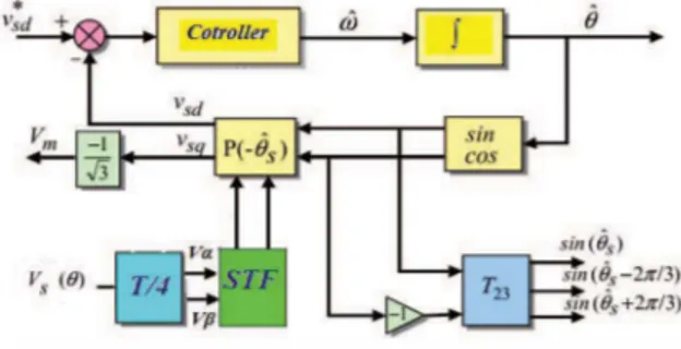
The PLL is used as a means to recover the information of the phase and the frequency. The basic form of the P.L.L is shown in Fig. 2, it's based on a feedback system tracking the grid instantaneous phase e using a controller. However, distorted grid voltages will reduce the performance. This drawback may be overcome by using a filter to eliminate the harmonics components in the voltages.
Fig. 2. The block diagram of the PLL with STF
The self tuning filter (STF) is used to extract the fundamental sinusoidal voltage wave from the distorted and asymmetrical grid voltage in u-p axes [II]. The STF, shown in Fig. 3, is represented by the transfer function defined as:
xa/3(s)
(s + k) +
jWeH(s)
=--
=k
(1)
xa/3(s)
(s + k)2 + wJ
Fig. 3. Self tuning filter STF
This technique works well if the harmonics components are at high frequencies and the filter do not change the voltage angular phases. In this paper, the conventional PLL has been improved by adding a self-tuning filter STF in the output of the abc/up transformation block.
III. VOLTAGE-LOOP CONTROLLER
The DC bus voltage control loop maintains the voltage at a constant reference value by controlling the process of charging and discharging of the capacitor. The causes of the variation are substantially the losses in the switches of the converter, in the coupling inductance and the variation of the load connected to the DC bus. The regulation of this voltage is effected by adjustment of the reference amplitude of the current taken to control the active power flow between the network and the DC bus. For this purpose, it is intended to compensate for any interference from the inverter side and the load side, causing a variation of the energy stored in the
capacitor. This loop has as input the reference voltage Vo' and the measured voltage Vo as shown in Figure 1.
The components of the boost chopper (transistor and diode) are considered ideal, absorbed instantaneous power is zero; this hypothesis with a power balance is independent of the presence of the DC-DC converter assuming that:
iL- . =lre!
(3)
.
(
dVO Vo)
P(l
-
cos(2wt))
= VolD = Vodt + Ii
(4)
Supposing iL;::;iref; to satisfy the constraint form iL, It IS certain that the ripples of 50Hz to DC bus voltage do not affect the calculation of the voltage whose bandwidth is very low. We therefore consider that equation (4) can be reduced to that of the average power. The main difference concerns the disappearance of 50Hz ripples due to power fluctuation. Controller role is to maintain the average voltage of the DC bus and not the instantaneous value, equation (4) becomes:
VSMlret
de dVOde2
VOde2
-
----''---- ==2
C
--
dt
+
--
R
(5)
The de indication is used to remind that only the average value ofVo
is expressed in this equation. As shown in (5), the control ofVOdc
is made possible by action onI
rejdc.
To calculate the controller parameters, we can linearize equation (5) around an operating point defined by(VOdcc
andI
rejdcc
).Tf(s)
is the transfer function of the system: Tf(s)
= QVOde =VsM
R
ks
8/deret 4Vode1 + RC s 1 + Ts s
21.78
1 + 0.2844 s
1) PI-Controller:
(6)
As shown in Fig. 1, the dc-bus voltage Va is compared to a
reference value vare!' The error is the input of the PI controller; the output of the controller is multiplied by
Isin wtl
of the PLL. This gives the reference current iref. Calculation of PI controller is determined conventionally by compensating the dominant pole and the imposition of a dynamic closed-loop, we can deduce the two parameters of the PI controller as follows:RC
BRVSM
KpI = - =
0.6091;
TpI =8 ( F )
=0.3858
TpI IT lev VOde
B: attenuation of the measured DC bus voltage,
lev: the closed loop cutoff frequency of the DC bus voltage
1c,,=45Hz.
The closed loop transfer function is by:
Vo
kt
voret 1 + Tt s
(7)
Fig. 4. Voltage loop controller for PFC
TABLE I. DESIGN SPECIFICATION AND CIRCUIT PARAMETERS Magnitude of supply voltage (Vmax) nv DC-Bus reference output voltage 100V
Output voltage ripples 5%
Load resistance 161 n
Input Inductance 5mH
Output Capacity 4700llF
Line Inductance 5mH
2) Fuzzy-Controller:
In recent years, the fuzzy logic control is increasingly used for controlling the static converter. Most non-linear control approaches require the availability of a mathematical model of the system. Control performance will be directly related to the accuracy of the used model. It allows for better performance and to compensate for nonlinearities and the various constraints on the modeling of the process [12]. In this part, the conventional PI controller is substituted by a fuzzy logic controller.
The advantage of fuzzy logic lies firstly in its similarity to human reasoning. Indeed, the operator decision is based on several variables described qualitatively and not through specific numerical values. Second, this logic is interesting because it allows the decision despite the absence of a complex system modeling upstream such nonlinear systems or variable structure systems. A fuzzy system realizes a no linear correspondence between a vector and a scalar output [13] [14], through the steps shown in Fig 5.
The global structure of the voltage regulation, with a fuzzy controller of the DC bus voltage, is illustrated in Figure 6.
The fuzzy controller developed in this section is PI . The two input variables are discretized with a sampling period Ts and normalized using normalization gains (Ge for error and G�e for the variation of the error) .They are defined by the following expressions:
The input error
e(k)=vorelk)-vo(k)
Error
variationM(k) = e(k)- e(k-l).
The dc bus voltage is controlled by adjusting the reference current
t
The table II shows the set of fuzzy rules used in the design of this controller. Human perception of the control system is so translated.
3) Fuzzy Adaptive PlD Controller :
PID controller is simple, stable, easy adjustment and high reliability, it is widely used in control processes but, most industrial processes have a nonlinear behavior, parameter variability with times and reduced mathematical model.
Fig. 5. Fuzzy logic controller scheme and the controlled process.
Fig. 6. Fuzzy logic controller for DC bus. TABLE II. CONTROL RULE TABLE OF THE FLC
NG ZE PG
NG NG NG ZE
ZE NG ZE PG
PG ZE PG PG
TABLE III. Fuzzy LOGIC CONTROLLER GAINS
NG EZ PG
·10 o
Fig. 7. Membership functions for Error. dError and output of FLC TABLE IV. RULE TABLE OF THE ADAPTIVE FUZZY LOGIC CONTROLLER
NG NP ZE PP PG NG NG NG NG NP ZE NP NG NP NP ZE PP ZE NG NP ZE PP PG pp NP ZE PP PP PG PG ZE PP PG PG PG
4th International Conference on Renewable Energy Research and Applications Palermo, Italy, 22-25 Nov 2015
Fig. 9. Membership functions for Error,dError and output of AFLC Tuning PID parameters is very difficult, poor robustness. The controllers based on the concepts of artificial intelligence, fuzzy logic and neural networks are attractive alternatives, and can improve the robustness of the process to be controlled, [15]. In this part, an Adaptive fuzzy PID controller is used to control the DC bus voltage in PFC. PID parameters are adjusted in real time under adaptive fuzzy control. Hence, the controller can be adapting to any change of parameter.
Fuzzy adaptive PID controller used in this paper has two inputs and one output. The structure of this controller is shown in Fig. 8. In Fuzzy adaptive PID controller only one output which is connected to Kp, Ki and Kd gains. The inputs of fuzzy inference system are the error (e), error change (de) and control signal respectively. Membership functions of inputs and output are shown in Fig. 9. Table IV shows the rule used in the fuzzy adaptive PID controller.
IV. SIMULATION AND RESULTS
The performance of the proposed control techniques has been analyzed and compared with the conventional control. In the first case the proposed control technique applied to the PLL have been simulated and compared under distorted voltage without connecting the PFC. The simulation results were carried using Matlab/Simulink. To validate the robustness of the new PLL, it is evaluated with the same voltages applied to the Conventional structure.
Grid I.Oltage 300. Vs 200. 100 <1l '" 1'l a O· > -100· -200· -300'· 0 0.02 0.04 0.06 0.08 0.1 Times
Fig. 10. Line voltage
PLL sin signal output 0.5 c 'in o -0.5 �---1+-t+--'---+--++---+--+--++ -1'· o 0.02 0.04 0.06 Times
Fig. II. PLL SIN signal output
0.08 0.1
Fig. 12. PLL based on self'tuning filter Sin signal output THD
Fig. 13. Conventional PLL Sin signal output THD.
Figure 11, 12 and 13 shows the results of the PLL for voltages source which contain harmonics 5, 7 and II. It is noted that the STF based PLL structure enables us to obtain a linear and periodic phase angle, and that the presence of STF improves the voltage signals quality in the (u,P) axes. The Proposed PLL provides a much reduced THD. Therefore, we get a unit sinusoids and very good qualities in the output of the PLL.
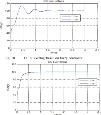
To show the effectiveness of fuzzy control based power factor correction boost converter, simulation has been carried out. The reference output voltage is taken as 100V. Figures 14, 15 and 16 illustrate the line current simulated waveforms, for the proposed methods at nominal load and constant voltage of 100 V. From this figures, it can be seen that the obtained results with the fuzzy control techniques are excellent. The grid current is sinusoidal and in phase with the line voltage. The total harmonic distortion (THD) is found less than 5%. Figures 17, 18 and 19 show that the output voltage is maintained constant at desired value for a steady-state error of 0.5 V.
TABLE V. PARAMETERS OF SIMULATION Parameters Value
DC bus voltage lOOV
Line inductance 5mH
PFC inductance 2mH
DC link capacitor 47OO!lF
Load resistance 1210
Fig. 14. Line Current using PI controller for DC bus.
Fig. 15. Line Current using fuzzy controller for DC bus.
Fig. 16. Line Current using fuzzy adaptive PID controller for DC bus.
Fig. 17. DC bus voltage based on PI controller .
Fig. 18. DC bus voltagebased on fuzzy controller .
Fig, 19, DC bus voltagebased on fuzzy adaptive PID controller , V. EXPERIMENTAL VALIDATION
In order to examine the robustness of the proposed controls, a real times implantation setup using the dSP ACE 11 03 (digital signal processor) controller board is done in LREA laboratory and shown in Fig. 20. For the real time implementation of the proposed controller, an inverter (SEMIKRON, 40KVA, 1200 V, 100A) used as a rectifier.
Experimental Test I-System without PFC: In this test, no PFC controller was implemented, the experimental results are shown in Fig. 21, it is observed that the performance of the system without PFC is not satisfactory since a THD more than 64% is observed in the line current having a low power factor around 0.8, it haven't a sinusoidal waveform. These results confirm the importance of PFC for the quality of energy in the power converters.
Fig, 20, Experimental test bench: 1: PC, 2: dSP ACE 1103 I/O connectors, 3: Power analyzer,4: Load,S: Current, voltage sensors, 6: Scope,
4th International Conference on Renewable Energy Research and Applications Palenno, Italy, 22-25 Nov 2015
Fig. 21. Experimental results in steady state without PFe.
Fig. 22. Experimental results with PFC unsig PI controller
Fig. 23. Experimental results with PFC unsig FLC controller
Fig. 24. Experimental results with PFC unsig Fuzzy adaptive PID controller.
Fig. 25. PFC Output voltage using PI controller.
Fig. 26. PFC Output voltage using FLC controller.
Fig. 27. PFC Output voltage using fuzzy adaptive PID controller.
Experimental Test 2-System with PFC: In this test, first step the PFC was implemented at nominal loading condition with nominal output voltage (121 ohm, 100 V), Figs. 22 and 25 show the system responses with PI controller. Reduction of the THD around 2.9%, the power factor is PF=0.984. The capacitor voltage is maintained close to its reference after a short transient. In the second step, the PFC was implemented with fuzzy controller, Figs. 23 and 26 show the responses of the system, the system exhibits excellent results with PFe. Reduction of the THO around 2.44%, the power factor is PF=0.98. The dc bus voltage is maintained close to its reference after a short transient, the line current has a sinusoidal waveform and in phase with the grid voltage. In the third step, the PFC was implemented with fuzzy adaptive
TABLE VI. TOTAL HARMONIC DISTORTION OF LINE CURRENT Condition(THD) PI AFLC PID FLC
Simulation 3.01% 2.99% 2.49% Experimental 2.91% 2.60% 2.44%
controller, Figs. 24 and 27 show the responses of the system, Reduction of the THD around 2.6%, the power factor is PF=0.98. The dc bus voltage is maintained close to its referen ce 1 00 V.
It is clear, from these results that the fuzzy control gives better performance than a conventional PI or fuzzy adaptive PID.
VI. CONCLUSION:
In this paper, the control of AC/DC converter which has a power factor near to the unit with sinusoidal line current was presented. The role of the DC bus voltage control loop is to maintain this voltage at a constant reference value by controlling the process of charging and discharging of the capacitor, by using conventional PI controller, fuzzy adaptive PID and fuzzy logic controller. The proposed controllers were simulated and experimental implemented. The results show that the FLC is more performance than the classical control (dc-bus voltage error equal to 0.9V and THD of line currents is 2.44%). The absorbed current is sinusoidal and in phase with the grid voltage with a near unity power factor. The experimental implementation show that the fuzzy controller performance is excellent, a good rejection of load variation disturbance and an excellent robustness are verified.
References
[1] Henry S. H. C" Eugene P. W. T., Hui S. Y R. "Development of a Fuzzy Logic Controller for Boost Rectifier with Active Power Factor Correction" IEEE, 1999. - P. 149-154.
[2] Jankovskis 1., Stepins D., Pikulins D." Lowering of EMI Noise in Boost Type PFC by the use of Spread Spectrum "Electronics and electrical Engineering. - Kaunas: Technologija, 2009. - No. 6(94). - P. 15-18.
[3] .lee-Woo L., Bong-Hwan K. "A Power-Factor Controller for Single Phase PWM Rectifier" IEEE Transaction on Industrial Electronics, 1999. -Vol. 46. - NO. 5. - P. 1035-1037.
[4] Masashi 0., Hirofumi M. "An AC/DC Converter with High Power Factor " IEEE Transaction on Industrial Electronics,2003. Vol. 50. No. 2.
-P. 356-361.
[5] Kessal A, Rahmani L, Gaubert .IP, Mostefai M. "Analysis and design of an isolated single-phase power factor corrector with a fast regulation". Electr Power Syst Res 2011;81:1825-31.
[6] Guo L, Hung .IY, Nelms RM. "Comparative evaluation of sliding mode fuzzy controller and PID controller for a boost converter." Electr Power Syst Res 20 11;81:99-106.
[7] Kessal A, Rahmani L, Gaubert .IP, Mostefai M. "Experimental design of a fuzzy controller for improving power factor of boost rectifier". Int J Electron 2012;99 (12): 1611-21.
[8] Chung HSH, Tam EPW, Hui SYR. "Development of a fuzzy logic controller for boost rectifier with active power factor correction. " In: I EEE Power Electronics Specialists Conference PESC'99, I; 1999. p. 149-54.
[9] Sagiroglu S, Colak I, Bayindir R. "Power factor correction technique based on artificial neural networks. " Energy Convers Manag 2006;47:3204-15.
[10] Martin K. H. e., Martin H. L. e., Chi K. T. "Practical Design And Evaluation of A 1 KW PFC Power Supply Based en Reduced Redundant Power Processing Principle " I EEE Transaction on Industrial Electronics, 2008. - Vol. 55. - No.2. - P. 665-673.
[11]L. Benchaita. « Etude, par simulation numerique et experimentation, d'un
filtre actif parallele il structure courant avec une nouvelle methode de contr61e commande « PhD Thesis of Institut National Poly technique de
Lorraine, Nancy, France, Octobre 1998.
[12] M.C Benhabib and S Saadate, "A New Topology for a Modular Active Power Filter". IEEE lSI 2005, June 20- 23,2005, Dubrovnik, Croatia [13] B. K. Bose,"Expert system, fuzzy logic and neural network applications
in power electronics and motion control," Proc. IEEE, vol. 82, no. 8, pp. 1303-1323, 1994.
[14] W.e. So, e.K. Tse, and YS. Lee, "Development of a fuzzy logic controller for dc/dc converters: design, computer simulation, and experimental evaluation," IEEE Trans. Power Electron, vol. I I, no. I, pp. 24-31, Jan. 1996.
[15] Z. Y Zhao, M. Tomizuka, and S. Isaks, "Fuzzy Gain Scheduling of PID Controller", IEEE Trans, On Systems, Man, and Cybernetics, Vol. 23, No. 5, Sep -Oct, pp. 1392-1398, 1993.