Abstract—This paper reports a novel remotely actuated
ma-nipulator for access to prostate tissue under magnetic resonance imaging guidance (APT-MRI) device, designed for use in a standard high-field MRI scanner. The device provides three-di-mensional MRI guided needle placement with millimeter accuracy under physician control. Procedures enabled by this device in-clude MRI guided needle biopsy, fiducial marker placements, and therapy delivery. Its compact size allows for use in both standard cylindrical and open configuration MRI scanners. Preliminary
in vivo canine experiments and first clinical trials are reported. Index Terms—Biomedical imaging, cancer, magnetic resonance
imaging, medical diagnosis, medical treatment.
I. INTRODUCTION
T
HIS PAPER reports the development of a novel access to prostate tissue under magnetic resonance imaging guid-ance (APT-MRI) manipulator for MR prostate imaging and pre-cision MRI guided needle placements and reports the results ofin vivo canine experiments and clinical trials. The manipulator
operates inside the spatial confines and high magnetic field of a standard “closed” MR scanner. The principal objective for the manipulator is to provide precise image guided targeting of a needle for therapeutic procedures and biopsy of the prostate. The manipulator is equipped with active fiducial tracking to en-code the position of the needle path and is remotely actuated by the physician from outside the bore of the MR scanner. A tar-geting system displays MR images, including the needle path, and provides a graphical user interface for the physician. We Manuscript received December 22, 2003; revised June 6, 2004. This work was supported in part by the National Science Foundation (NSF) under Grant NSF ERC 9 731 478, in part by the US Army under Grant PC 10029, in part by the National Institutes of Health (NIH) under Grant RO1 HL57483, Grant RO1 HL61672, and Grant RO1 EB02963. Asterisk indicates corresponding author.
A. Krieger is with the Department of Radiology and the Department of Me-chanical Engineering, The Johns Hopkins University, Baltimore, MD 21218 USA.
R. C. Susil is with the Department of Biomedical Engineering, The Johns Hopkins University, Baltimore, MD 21218 USA.
C. Ménard was with the Radiation Oncology Branch, NCI, NIH-DHHS, Fred-erick, MD 30325 USA. She is now with the Department of Radiation Oncology, Princess Margaret Hospital, Toronto, ON M5G 2M9, Canada.
J. A. Coleman is with the Urologic Oncology Branch, NCI, NIH-DHHS, Frederick, MD 30325 USA.
G. Fichtinger is with the Department of Radiology, The Johns Hopkins Uni-versity, Baltimore, MD 21218 USA.
E. Atalar is with the Department of Radiology, The Johns Hopkins University Baltimore, MD 21218 USA, and also with the Department of Electrical and Electronics Engineering, Bilkent University, Ankara, 06533, Turkey.
*L. L. Whitcomb is with the Department of Mechanical Engineering, 123 Latrobe Hall, 3400 N. Charles Street, The Johns Hopkins University, Baltimore, MD 21218 USA (e-mail: [email protected]).
Digital Object Identifier 10.1109/TBME.2004.840497
have recently reported the use of a first generation prototype of this manipulator [4], [8], [13]. This paper focuses on the de-sign, materials and construction of a second generation device for clinical trials. The results of these clinical trials, mentioned briefly herein, are reported in [14].
This paper is organized as follows: The remainder of this sec-tion reviews background informasec-tion about prostate diseases and treatments, compares imaging modalities for the prostate, and reviews previous work in this area. Section II reports the design of the manipulator. Section III reports the performance of the manipulator in in vivo canine studies and clinical trials.
A. Background and Motivation
Prostate cancer is the most common noncutaneous cancer in American men. In 2003, there will be an estimated 220 900 new cases of prostate cancer in the United States and 28 900 men will die of this disease [6]. There are two common screening methods for prostate cancer: the prostate-specific antigen test (PSA) and the digital rectal exam (DRE) [10]. The PSA concen-tration in the blood estimates the likelihood of prostate cancer, but is not conclusive. For the DRE, the physician determines whether the prostate gland is enlarged or whether abnormal nod-ules are present.
When a PSA level is higher than normal or a DRE shows abnormal results, needle biopsy will normally be recommended to determine if a tumor exists and whether the tumor is benign or malignant. The current standard of care for verifying the existence of prostate cancer is transrectal ultrasound (TRUS) guided biopsy. Under ultrasound guidance, the physician places a biopsy needle through the wall of the rectum into the prostate gland. The needle removes a small cylinder of tissue, which is examined under the microscope to determine if cancer is present. Several biopsy samples are normally taken from dif-ferent areas of the prostate. Usually, 6–18 cores are removed (from upper, mid, and lower areas of the left and right sides) to obtain a representative sample of the gland and to determine how much of the gland is affected by the cancer.
TRUS provides limited diagnostic accuracy and image reso-lution. In [17], the authors conclude that TRUS is not accurate for tumor localization and therefore precludes the precise identification and sampling of individual cancerous tumor sites. As a result, the sensitivity of TRUS biopsy is only between 60% and 85% [11], [16]. Magnetic Resonance Imaging (MRI) with an endorectal coil affords images with higher anatomical resolution and contrast than can be obtained using TRUS [17]. Although computed tomography (CT) X-Ray imaging is capable of high spatial resolution, MRI’s superior soft-tissue 0018-9294/$20.00 © 2005 IEEE
discrimination enables the identification of individual can-cerous lesions. MRI guided transperineal prostate biopsy has been demonstrated inside an open MRI scanner [5]. While the transrectal approach is generally well tolerated by patients, the transperineal approach dictates a longer needle path, which may increase patient discomfort.
B. Previous Work in MRI Compatible Interventional Devices
Masamune and colleagues [9] report an in-MRI robot for stereotactic brain surgery for use with open MRI. In [7], Kaiser and colleagues report a 6 degrees of freedom (DOF) robotic system for breast biopsy for the use inside of a “closed” MR scanner. In [2], Chinzei and colleagues report a surgical assist robot for use inside an open MRI scanner. This robot can be used for transperineal access to the prostate. In [1], Beyersdorff and colleagues report a device for prostate biopsy inside a “closed” MR scanner utilizing passive fiducial tracking. In [15], Tajima and colleagues report an MR compatible surgical manipulator for heart intervention designed for vertical magnetic field open-configuration MR imagers. In contrast to these approaches, we have developed a remotely actuated manipulator that operates inside a conventional high-field MRI scanner, which has higher signal-to-noise ratio (SNR) than most open configuration scan-ners and employs transrectal access to the prostate. This paper reports the first successful device combining MR imaging and tracking coils with a needle for the purpose of image guided prostate intervention.
II. MANIPULATORDESIGN
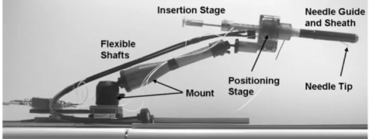
This section reports on the design of the manipulator. Place-ment schematic and the components of the manipulator are de-scribed. In addition, design, needles, encoding system and ma-terials for the manipulator are reported. Fig. 1 shows a photo of the manipulator. The manipulator consists of needle guide and rectal sheath, positioning stage, insertion stage, flexible shafts, and mount.
A. Device Operation
Fig. 2 shows a computer-aided design (CAD) drawing of the placement and operation of the robotic device. The device is comprised of a rectal sheath, which is placed adjacent to the prostate in the rectum of the patient and a needle guide, containing a curved needle channel. The sheath is held sta-tionary during the procedure while the needle guide rotates and translates within the sheath. The needle exits the needle guide
Fig. 2. CAD drawing of needle guide and sheath with curved needle channel. The needle is guided inside the curved needle channel of the needle guide and advanced through a window in the rectal sheath into the prostate.
Fig. 3. CAD drawing of needle guide and sheath with straight needle channel. A 20 needle channel for distal parts of the prostate and a 30 channel for proximal parts of the prostate.
through a window in the sheath at a 45 angle between axis of the guide and the needle for optimal coverage of the prostate. Rotation and translation of the needle guide and insertion of the needle are the three DOF necessary for the manipulator to place the needle at a target within the prostate.
Some applications require a straight needle path (Fig. 3). Biopsy, for example, requires fast actuation of the biopsy needle to reliably harvest good biopsy samples. Fast needle actuation is difficult to achieve with a curved channel due to friction induced by the bending of the needle. A straight needle path is therefore preferred for biopsies.
While the curved needle channel allows for unobstructed cov-erage of the prostate, even with high exit angles, the straight approach is complicated by the constraint of avoiding obstruc-tion by tissue surrounding the proximal end of the needle guide. Therefore, the curved approach is preferable for most applica-tions. Two different needle guides with different needle chan-nels were designed to accommodate for various applications: 1) a needle guide with curved needle channel for injections and fiducial marker placements, and 2) a needle guide with a straight needle channel for biopsies. The sheath for the straight approach contains two slots as windows: one on top for the entry of the needle and one on the bottom for the exit. In straight needle ver-sion, the sheath rotates together with the needle guide. A key inside the needle guide riding in the top slot provides the rota-tion of the sheath. For better coverage of the prostate, the needle guide for the straight approach contains two needle channels: A channel with 30 exit angle for proximal parts of the prostate and a channel with 20 exit angle for the distal parts.
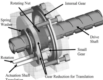
Fig. 4. Transparent CAD drawing of the positioning stage. Rotation of the actuation shaft for translation is converted into pure translation of the drive shaft. Rotation of the actuation shaft for rotation is converted into pure rotation of the drive shaft.
B. Principal Mechanical Components
The positioning stage provides translation and rotation of the needle guide. Fig. 4 shows a semi-transparent view of the posi-tioning stage. It consists of a drive shaft, which is concentrically connected to the needle guide. It contains a through-hole for the needle to pass through the manipulator. Translation is provided through an actuation shaft rotating a nut over a gear reduction, as shown in Fig. 4. The threaded nut drives the shaft. A second actuation shaft rotates a small gear, which engages an internal gear. The internal gear is held stationary by the housing. Upon rotation of the small gear, the entire inner assembly including the actuation shafts rotates. Two keys riding in two horizontal grooves on the drive shaft and which are held by the inner as-sembly rotate the drive shaft. A spring washer provides enough axial load to prevent unintentional rotation of the drive shaft. The actuation shafts exit the housing via a radial slot on the left side of the housing allowing for 140 degrees of rotation, without compromising structural stability.
Two bidirectional, nonmagnetic phosphor bronze flexible shafts (SS White Technologies, Piscataway, NJ) are attached to the actuation shafts to provide remote actuation from outside the scanner bore. For protection the flex shafts are encased in nylon tubing. The rectal sheath for the curved approach attaches to the positioning stage with a click-in mechanism, comprised of a nylon ball and a flat spring mating with a spherical dent on the right housing of the positioning stage. A similar click-in mechanism is used for attaching the sheath for the straight approach. However, a circular groove is used instead of the spherical dent, to allow for rotation of the sheath. A medical grade heat shrink (Tyco Electronics Corporation, Menlo Park, CA) is fitted around the sheath and covers the window to prevent tissue from being trapped between window and needle guide.
The insertion depth is set by the insertion stage by increasing and decreasing the length of a tubular stop for the needle with a set screw mechanism. A scale is attached to the stop to man-ually set the length and thus the insertion depth of the needle. The insertion stage docks to the drive shaft of the positioning
Fig. 5. Signal to noise contours for 200- and 300-mm-wide imaging coil. The graphs show contours of measured SNR level of a cross section of the imaging coil. XY units are in millimeters. The position of the coil is indicated by the arrows.
stage with a click in mechanism, similar to the one of the sheath. A tube is fitted inside the drive shaft to protect the drive shaft and the positioning mechanism from getting in contact with the needle. This limits the number of parts requiring sterilization to the sheath, the needle guide, and the insertion mechanism. The mount consists of a Drylin®T-slide and rail assembly (Igus
Inc., E. Providence, RI) for motion along the main axis of the scanner bore and an arm with two integrated ball joints (Man-frotto Trading, Milano, Italy) for adjusting horizontal and ver-tical position and orientation of the device.
C. MR Coils
The manipulator contains two types of MR coils: an imaging coil and tracking coils for position encoding.
The imaging coil is looped around the window of the sheath, resting in a groove machined into the sheath. Two design ideas were explored for the sheath containing the imaging coil: with cylindrical cross section and a sheath with elliptical cross section. An elliptical sheath would increase the width of the imaging coil, yielding higher SNR levels. The cylindrical sheath has the advantage of easier machinability and better patient comfort. To make a design choice, we compared the SNR level for an imaging coil on a flexible endorectal coil (MedRad Inc., Indianola, PA) with auto tuning capability of a width of 300 mm, which is achievable with the elliptical design to the SNR level for the cylindrical design with an imaging width of 200 mm. Fig. 5 shows both SNR maps. The increase in SNR of the elliptical design was considered too small to justify higher machining costs and potential increase of patient discomfort, leading to the decision to favor the cylindrical design.
Three tracking micro coils are placed into the manipulator to encode the position of the needle channel. The method is explained in Section II-E.
D. Nitinol Needles
For accurate targeting with the curved approach, the needle needs to exit the channel of the needle guide along a straight trajectory tangential to the arc at the point of exit. A higher exit angle allows for better coverage of the prostate. Higher exit
for an 18-mm-diameter needle guide. MRI Devices Daum pro-vided the grinding of the needle tips and assembly of the con-nectors and needles to our specifications for use with this new design.
E. 3-D Spatial Position Sensing
We explored three methods for encoding the device posi-tion in the MR scanner: Electro optic encoders, passive fiducial tracking and active fiducial tracking.
Electro-optical encoders reliably and accurately encode the position of a robotic joint and were successfully implemented in the MRI environment by using optical connection for the de-velopment of a surgical assist robot [2]. However, they require accurate calibration between device coordinate system and MRI coordinate system and suffer from inaccuracies caused by ma-terial deflection.
For passive fiducial tracking, fiducial markers composed of water doped with gadolinium-DTPA or other contrast agents are rigidly attached to the end-effector of the device. Gadolinium-DTPA is a commonly used contrast agent that produces large MR signal. Volumetric MR images are taken and after segmenting the marker position in the images the device position can be determined. This method provides position of the end-effector in MRI coordinates, but in order to achieve good accuracy the images have to be of high quality which takes a lot of time, preventing any real time tracking. Additionally, segmentation of the marker position from the rest of the image is very time consuming.
Active fiducial tracking proved to be a fast and accurate encoding method [3]. This method utilizes three tracking micro coils rigidly embedded in the end-effector of the device, which pick up their spatial position in the MRI scanner. A micro coil consists of a wire coil wrapped around a tube filled with a gadolinium-DTPA water solution. A cable connects the antenna coils to the imaging channels of the MRI scanner. The position of the center points of the gadolinium-DTPA tubes is determined by performing a series of twelve 1D projections along different directions, using a frequency encoding gradient. A special MR pulse sequence to produce a series of projections was written. This yields an over-determined linear system for the position of the points, which can be solved using a least square algorithm. The registration sequence takes approxi-mately 50 ms allowing for real time tracking. Two tracking coils are positioned along the axis of the needle guide, while the third coil is placed off axis in the rotating part of the positioning stage, encoding the rotation of the needle guide, Fig. 6.
Fig. 6. Detailed picture of sheath, needle guide and positioning stage. The picture shows: the imaging coil, embedded in the rectal sheath, tracking coil 1 and 2 built into the needle guide along the axis, and tracking coil 3, which is attached to the rotating part of the positioning stage.
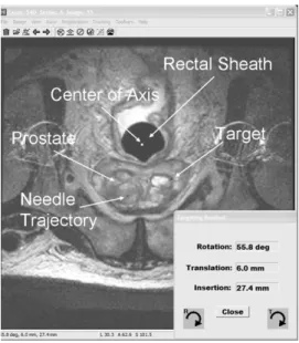
Fig. 7. Screen shot of the visualization and targeting program. An axial T2 weighted MR image containing prostate and rectal sheath is displayed. Intersection points of the device axis and the needle trajectory with the MRI image are visualized as well as the selected target point. The necessary rotation, translation, and insertion values to reach the target are displayed in the lower right corner.
F. MR Image Guidance Software
We developed a custom visualization and targeting program which displays MR images and reads the tracking coil positions. Fig. 7 shows a screen shot of the visualization and targeting pro-gram. An axial T2 weighted MR image containing prostate and rectal sheath is displayed. The program overlays a schematic view of the device represented by the intersection points of the device axis and the needle trajectory with the MRI image. After selecting a target position, the program calculates the inverse kinematics and displays necessary rotation, translation and in-sertion to reach the target. The program is displayed on a screen next to the scanner and the translation, rotation and insertion values are updated every second while the physician uses the ac-tuation shafts of the positioning stage to move the needle guide to the target. The tracking sequence is stopped once the needle trajectory is aligned with the target. The insertion depth is set using the insertion stage and the needle is advanced.
Fig. 8. Graph of tracking coil errors with aluminum ball joint, brass gear and phosphor bronze flex-shaft. The errors in mm are displayed over the displacement from the tracking coil in mm. The three lines indicate the position errors for coil 1, coil 2, and coil 3, respectively. Coil 1 is initially placed adjacent to the metal component. Coil 2 and 3 are not influenced by the metal object.
Fig. 9. Angular and translational error distribution for active fiducial tracking. The graphs show histograms of angular and translational encoding error in millimeters and degrees.
G. Materials
Due to the presence of a strong magnetic field inside of an MRI scanner, the use of any ferromagnetic materials is prohib-ited. Additionally, even nonmagnetic metals can create imaging artifact. These artifacts are caused by a disturbance of the mag-netic field due to difference in susceptibility of the metal and surrounding objects. This disturbance also affects the readings of the tracking coils in the vicinity of metals. The magnitude of the disturbance is dependant on the size and on the material of the metal. Very small nonmetallic metals create only a small localized susceptibility artifact and can be neglected on MR im-ages and for tracking coil readings.
To avoid obstruction in anatomical images and introduction of errors in the coil readings, plastic materials are used to build needle guide and sheath, which are in closest vicinity to the field of view (FOV) of the anatomical MR images. Only very small metallic components are used to build these parts: Brass screws for fastening the needle guide to the drive shaft, the flat spring for the click in mechanism of the sheath, which is comprised of phosphor bronze and a thin walled brass tubular liner (Special Shapes Inc.) for the needle channel to protect the plastic from being marred with the needle. Functionality of the manipulator
could improve, if parts further away from the FOV may contain more metallic parts.
We developed a test methodology to determine the influence of metallic components on tracking coil readings, which also indicates artifacts on MR images to determine the minimal dis-tance of installation of the components to the FOV and to the tracking coils. The position stage was used for stepped transla-tion of a needle guide containing three tracking coils. The posi-tion stage was set up to place one coil (coil 1) initially adjacent to the metal component and the other 2 coils (coil 2 and 3) out of the influenced region to provide undisturbed readings. The needle guide was translated away from the metal component and coil errors over the distance to the component were recorded.
Fig. 8 shows the results of testing a phosphor bronze flex-ible shaft, a brass gear and an aluminum ball joint. The position error for a tracking coil placed in direct vicinity of the phosphor bronze flexible shaft did not measurably increase compared to the tracking error distribution obtained without any metal parts in the vicinity shown in Fig. 9. This allows us in our design to place the flexible shafts right next to the positioning stage, which contains one of the tracking coils. The error introduced by placing a coil close to the aluminum ball joint significantly
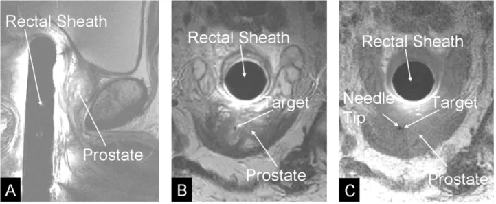
Fig. 10. MR images of the prostate. Panel A: Sagital T2 weighted MR image containing rectal sheath and prostate. Panel B: Axial T2 weighted MR image containing prostate and rectal sheath with selected target. Panel C: Axial T1 weighted image after insertion of the needle, verifying accurate targeting, thus small displacement between target point and the void created by the needle tip.
increased. However the error falls of rapidly to the level of the tracking error distribution without metal when the coil is further than 10 mm away from the ball joint. Adding a safety margin of 20 mm we placed the aluminum ball joint 30 mm away from the positioning stage. The brass gears produced unacceptable errors in the tracking coils and were replaced by plastic gears.
III. PERFORMANCEEVALUATION
All interventions were performed on a GE Signa Excite 1.5 T MR scanner (GE Medical Systems). A protocol was devel-oped for MRI-guided gold fiducial marker placements on pa-tients with prostate cancer prior to treatment with external radi-ation beam therapy. Fiducial markers are used to adjust for daily set-up changes to optimize targeting of external beam radiation therapy [12]. The two primary goals of this study were to val-idate the needle targeting accuracy of the manipulator system in clinical practice and to assess the effects of fiducial markers on the outcome of radiation therapy. Four markers were placed into the prostate of each patient using the manipulator system. The target positions for the markers were selected to achieve a diamond like pattern, with two markers placed to the left and right in the middle of the prostate (mid-gland), one marker in the lower part of the prostate (apex), and one marker in the upper part of the prostate (base). After the markers were placed in the prostate, MRI images of the prostate were taken in the radia-tion treatment posiradia-tion without the transrectal device. These im-ages are co-registered to CT scans using the fiducial markers as common landmarks to aid in target delineation, and digitally re-constructed radiographs (DRRs) are compared to the treatment portal x-rays taken prior to every radiation dose, to achieve op-timal beam coverage of the prostate gland. As of today, five pa-tients received implantation of markers. All 20 markers were implanted without complications. For each marker the physi-cian selected the desired marker position on T2 weighted axial and sagital MR images (Fig. 10). The manipulator was actu-ated to the target location and the physician inserted the needle.
After the needle was inserted, MR images were taken to con-firm that the location of needle tip was acceptable. The marker was dropped and another MR image was taken after the needle was extracted to visualize the marker position. Target location, needle tip location and center of marker location were recorded for each marker placement to assess the targeting accuracy of our system. The displacement errors for the needle and for the marker were determined on the MRI images as the distance of the needle tip and the center of the marker respectively to the planned target location. The average in-plane displacement error for the needle tip of 20 needle placements was 1.3 mm with a maximum of 2.3 mm. In none of the 20 cases was the needle tip more than one slice (3 mm) away from the slice containing the target position. The average marker displacement error was 4.8 mm with a maximum of 8.3 mm. The increased displace-ment errors for the marker compared to the needle tip were considered to be caused by deformation of the prostate tissue during insertion of the needle. After the marker is dropped and the needle is extracted, the tissue around the marker relaxes and increases the displacement error.
This section reports on the performance evaluation of the manipulator. First, the accuracy of the tracking method was tested. Subsequently, the manipulator was tested in in vivo canine studies and clinical trials.
A. In Vitro Tracking Accuracy Studies
An accuracy test with the proposed tracking method was per-formed, Fig. 9, using the positioning stage. Precise, stepped translations and rotations were performed and coil positions were recorded after each step to calculate encoding errors. Step size was 1.27 mm for translation and 2 for rotation. The av-erage absolute error for translation was 0.19 mm with a standard deviation of 0.25 mm. For rotation the average absolute error was 0.33 with a standard deviation of 0.42 . For a target that is 30 mm away from the axis of rotation, a rotational error of 0.33 yields a rotational displacement of 0.17 mm. The combined mean displacement due to translational and rotational tracking
A first-generation prototype of this manipulator was used to demonstrate feasibility for different applications of prostate intervention and to assess the accuracy of needle placements. Needle placements, intraprostatic injections, and fiducial markers placements were performed in anesthetized canines, as reported in [13]. The usefulness of the manipulator for ac-curate needle placements, intraprostatic injections and fiducial markers placements was demonstrated. The maximum in-plane needle displacement error for 4 needles was 2 mm. Because of a slice thickness of 3 mm for the MRI images it is more difficult to exactly determine the error of the insertion depth. In all cases, however, the needle tip was visible in the target slice.
C. In Vivo Clinical Accuracy Studies
In addition to the fiducial marker placements, four biopsy pro-cedures were performed with no adverse patient outcome. The average in-plane displacement error for 20 biopsy needles was 1.8 mm. Further clinical trials are in progress.
IV. CONCLUSION ANDDISCUSSION
This paper reported the development of a novel APT-MRI manipulator for MR prostate imaging and precision MRI guided needle placements and reported the preliminary results of in
vivo canine experiments and clinical trials. Precise image guided
targeting of a needle for intraprostatic marker placement and biopsy was achieved.
Tissue deformation was considered to be the main reason for displacement errors. Reducing the tissue deformation, for ex-ample by increasing the insertion speed of the needle or fixating the prostate during insertion will be an objective for future work. Another objective will be to enable the use of the manipulator in a 3 T system. The increased SNR of the 3 T system could im-prove the MR image quality and facilitate the use of functional MRI, such as MR spectroscopy for better target selection.
ACKNOWLEDGMENT
The authors thank J. A. Derbyshire, Ph.D. and E. McVeigh, Ph.D. for help with the tracking coils; J. Polzin for assis-tance with gradient dewarping; Y. Oner, A. El-Sharkawy, and A. Yung for help with experiments and intrarectal imaging coil design; P. Karmarkar for help with the nitinol needles; W. Krug, M. Franckowiak, and T. Shelly for machining; K. Ullman, P. Choyke, M.D. and P. Guion for help with clinical trials.
REFERENCES
[1] D. Beyersdorff, A. Winkel, P. Bretschneider, B. Hamm, S. Loening, and M. Taupitz, “Initial results of MRI-guided prostate biopsy using a biopsy device in a closed MR imager at 1.5 T,” in Proc 88th Scientific Assembly
and Annu. Meeting Radiological Society of North America, Chicago, IL,
2002, p. 629.
in Computer Science, vol. 2488, Proceedings of the Fifth International
Conference on Medical Image Computing and Computer-Assisted In-tervention, 2002, pp. 91–98.
[5] N. Hata, M. Jinzaki, D. Kacher, R. Cormak, D. Gering, A. Nabavi, S. G. Silverman, A. V. D’Amico, R. Kikinis, F. A. Jolesz, and C. M. C. Tempany, “MR imaging-guided prostate biopsy with surgical navigation software: Device validation and feasibility,” Radiology, vol. 220, no. 1, pp. 263–268, Jul. 2001.
[6] A. Jemal, T. Murray, A. Samuels, A. Ghafoor, E. Ward, and M. J. Thun, “Cancer statistics, 2003,” CA Cancer J. Clin., vol. 53, no. 1, pp. 5–26, 2003.
[7] W. Kaiser, H. Fischer, J. Vagner, and M. Selig, “Robotic system for biopsy and therapy of breast lesions in a high-field whole-body mag-netic resonance tomography unit,” Investigat. Radiol., vol. 35, no. 8, pp. 513–519, Aug. 2000.
[8] A. Krieger, R. C. Susil, A. Tanacs, G. Fichtinger, L. L. Whitcomb, and E. Atalar, “A MRI compatible device for MRI guided transrectal prostate biopsy,” presented at the 10th Scientific Meeting Society of Magnetic Resonance Imaging in Medicine, Honolulu, HI, 2002, p. 338. [9] K. Masamune, E. Kobayashi, Y. Masutani, M. Suzuki, T. Dohi, H. Iseki,
and K. Takakura, “Development of an MRI-compatible needle insertion manipulator for stereotactic neurosurgery,” J. Image-Guided Surg., vol. 1, no. 4, pp. 242–248, Dec. 1995.
[10] J. Naitoh, R. L. Zeiner, and J. B. Dekernion, “Diagnosis and treatment of prostate cancer,” Am. Fam. Physician, vol. 57, no. 7, pp. 1531–1539, 1541–1512, 1545–1547, Apr. 1998.
[11] M. Norberg, L. Egevad, L. Holmberg, P. Sparen, B. Norlen, and C. Busch, “The sextant protocol for ultrasound-guided core biopsies of the prostate underestimates the presence of cancer,” Urology, vol. 50, no. 4, pp. 562–566, Oct. 1997.
[12] G. Pang, D. J. Beachey, P. F. O’Brian, and J. A. Rowlands, “Imaging of 1.0-mm-diameter radiopaque markers with megavoltage x-rays: An improved online imaging system,” Int. J. Radiat. Oncol. Biol. Phys., vol. 52, no. 2, pp. 532–537, Feb. 2002.
[13] R. C. Susil, A. Krieger, J. A. Derbyshire, A. Tanacs, L. L. Whitcomb, G. Fichtinger, and E. Atalar, “System for MR image-guided prostate interventions: Canine study,” Radiology, vol. 228, no. 3, pp. 886–894, Sep. 2003.
[14] R. C. Susil, C. Menard, A. Krieger, J. Coleman, K. Camphausen, P. Choyke, G. Fichtinger, L. L. Whitcomb, C. N. Coleman, and E. Atalar, Transrectal prostate biopsy and fiducial marker placement in a standard 1.5 T MRI scanner, 2004, submitted for publication.
[15] F. Tajima, K. Kishi, K. Nishizawa, K. Kan, H. Ishii, M. G. Fujie, T. Dohi, K.-I. Sudo, and S.-I. Takamoto, “A magnetic resonance compatible sur-gical manipulator: Part of a unified support system for the diagnosis and treatment of heart disease,” Adv. Robot., vol. 17, no. 6, pp. 561–575, Sep. 2003.
[16] M. K. Terris, “Sensitivity and specificity of sextant biopsies in the de-tection of prostate cancer: Preliminary report,” Urology, vol. 54, no. 3, pp. 486–489, Sep. 1999.
[17] K. K. Yu and H. Hricak, “Imaging prostate cancer,” Radiol. Clin. North
Am., vol. 38, no. 1, pp. 59–85, Jan. 2000.
Axel Krieger received his B.S. and M.Sc. degrees in
mechanical engineering from the University of Karl-sruhe, KarlKarl-sruhe, Germany, in 2001. He worked as a Research Associate at the Department of Radiology, The Johns Hopkins University, Baltimore, MD, from 2001–2003. Currently he is working towards the Ph.D. degree in the Mechanical Engineering Department at The Johns Hopkins University.
His research interest focuses on the develop-ment of MRI compatible devices for MRI-guided interventions.
University of Calgary, Calgary, AB, Canada, in 1996 and completed her residency in radiation oncology at the University of Alberta, Edmonton, AB, Canada, in 2001.
Until 2003 she was an ASTRO Translational Re-search Fellow in the Radiation Oncology Branch of the National Cancer Institute, NIH. She then held a Staff Clinician appointment and headed the Radia-tion Oncology Molecular Imaging SecRadia-tion in the Ra-diation Oncology Branch, NCI, where she pursued research in the development, validation, and clinical application of novel MR imaging techniques to cancer radiotherapy. She is now appointed as a Clinician Scientist in the Radiation Medicine Program at Princess Margaret Hospital in Toronto, ON, Canada.
Jonathan A. Coleman received the B.A. degree
from Bard College, Annandale-on-Hudson, NY, in 1989 and the M.D. degree (1996) and Residency training in urology (2002) at Cornell University Medical College and Memorial Sloan Kettering Cancer Center,New York.
He then entered the National Cancer Institute (NCI) as an A.F.U.D. sponsored fellow in Urologic Oncology from 2002–2004. He currently holds an appointment as a senior clinical investigator and surgeon at the NCI where he is active in ongoing research and the surgical treatment of genitourinary malignancies including prostate, bladder and kidney cancer. He has published in the field of ra-diographic imaging and tissue characterization using ultrasound as well as contributing to chapters on urologic oncology in several texts. His current research interests are in imaging and detection strategies for prostate cancer, developing molecular targeting therapies for bladder cancer and the use of laparoscopic surgical approaches in the treatment of prostate and kidney cancer.
Ergin Atalar received the B.S. degree from Bogazici
University, Istanbul, Turkey, in 1985; the M.S. de-gree from the the Middle East Technical University, Ankara, Turkey, in 1987; and the Ph.D. degree from Bilkent University, Ankara, Turkey in 1991, respec-tively.
Immediately after graduation, he joined The Johns Hopkins University, Baltimore, MD, as a Postdoc-toral Fellow where he is currently the Director of the Center for Image Guided Intervetions and Professor of Radiology with joint appointments in the Depart-ments of Electrical and Computer Engineering and Biomedical Engineering. He is also a Visiting Professor of Electrical and Electronics Engineering of the Bilkent University. His main research areas are Magnetic Resonance Imaging (MRI)-guided vascular interventions and MRI-guided prostate interventions.
Louis L. Whitcomb (S’86–M’95–SM’02)received
the B.S. and Ph.D. degrees from Yale University, New Haven, CT, in 1984 and 1992, respectively.
From 1984 to 1986, he was an R&D Engineer with the GMFanuc Robotics Corporation. From 1992 to 1994, he was a Postdoctoral Fellow at the Woods Hole Oceanographic Institution and at the University of Tokyo. He holds numerous patents in the field of robotics. His research focuses on the design, dy-namics, and control of nonlinear dynamical systems. He is a Professor in the Department of Mechanical Engineering, with joint appointment in the Department of Computer Science, at The Johns Hopkins University.