IEEE TRANSACTIONS ON ANTENNAS AND PROPAGATION, VOL. 43, NO. 8, AUGUST 1995 793
Accurate Simulation
of Reflector Antennas
by the Complex Source-Dual Series
Taner Oguzer,Ayhan Altintag,
Senior Member, IEEE, andAlexander I. Nosich,
Approach
Senior Member, IEEEAbstract-The radiation from circular cylindrical reflector antennas is treated in an accurate manner for both polarizations. The problem is first formulated in terms of the dual series equa- tions and then is regularized by the Riemann-Hilbert problem technique. The resulting matrix equation is solved numeridy with a guaranteed accuracy, and remarkably Little CPU time is
needed. The feed directivity is included in the analysis by the complex source point method. Various characteristic patterns are
obtained for the front and offset-fed reflector antenna geometries with this analysis, and some comparisons are made with the
high frequency techniques. The directivity and radiated power properties are also studied.
I. INTRODUCTION
OR electrically large reflectors, high frequency techniques
F
such as the aperture integration (AI) and the geometrical theory of diffraction (GTD) are commonly employed for predicting the far-field radiation characteristics of reflector antennas. Recently, in the papers of Suedan and Jull [l], [2], it is demonstrated that the complex source point(CSP)
method can be successfully used in combination with AI or GTD to take account of source directivity in reflector antenna simulations, since the replacement of the real coordinate of a uniform source with the complex one generates a beam field in real space [3]. Both AI and GTD, however, have well- known intemal shortcomings for reflector antenna problems. The former gives less accurate results off the main beam and completely fails in shadow region. The latter, oppositely, is not applicable in main beam direction. That is why, usually, one has to compose the results of two methods without any clear rule of choosing the matching point. Although these high frequency techniques are applicable to many practical problems, the range of validity of the results, in terms of acceptable accuracy, is unpredictable.Provided that the reflector is not electrically large, more accurate results can be obtained by numerical techniques such as method of moments
(MOM).
Normally, the matrix size involved in computations with this method is 10-30 times the parameter D/X, whereD
is the reflector dimension, and A is the wavelength. If the entire-domain basis functionsManuscript received December 13,1993; revised August 8,1994. This work was supported in part by NATO's Scientific Affairs Division in the framework of the science for stability programme, "AK, and Telecommunications Advancement Foundation of Japan.
T. Oguzer and A. AltinQ are with the Department of Electrical and Electronics Engineering, Bilkent University 06533 Bilkent, Ankara, Turkey.
A. I. Nosich is with the Institute of Radiophysics and Electronics, Ukrainian Academy of Sciences, Kharkov, 310085, Ukraine.
IEEE Log Number 9412886.
are used [4], the matrix size can be smaller, but the matrix filling time increases impressively. In any case, the accu- racy and convergence properties are quite dependent on the implementation.
Thus, there is still a need for a technique for the analysis and simulation of the reflector antennas with any desired accuracy. We present such a technique for circular cylindrical reflectors in which the dual series formulation is used in combination with the complex source approach. The aim is to demonstrate the unique opportunities offered by using this combination. In the core of the analysis, there lays the idea of regularization, i.e., a partial inversion of original integral operator. In our treatment, the inverted part of the integral operator is its static part. First, we reduce the problem to dual series equations [5]-[7] for surface current expansion coefficients. Then, we extract certain canonical equations and solve them exactly using the Riemann-Hilbert problem technique. The details of this approach, as it is used here, can be found in [7]-[9]. The resulting matrix equations enable one to conclude two facts of primary importance. First, the exact solution (of infinite matrix equation) really exists and second, it can be approximated with a desired accuracy (within digital precision) by solving truncated equations of large enough order. Actually, in far-field computations with the uniform accuracy of 0.1 %, the needed matrix size is onIy 6D/X plus 5-10 for a realistic front-fed reflector with 60 degree-wide aperture.
To use the conventional dual series approach for the sim- ulation of reflector antennas, one has to restrict the reflector geometry to a circular cross section. Although actual reflectors are of parabolic shape, the aperture dimensions compared to focal distance are often rather small. This offers a way to approximate the parabola by a part of a circle with great accuracy and thus avoid the modification of the method.
The organization of the paper is as follows. In Section I1 we discuss the formulation of the problem. Section 111 is concerned with the approximation of a parabolic reflector by a circular one and the range of validity of such an approximation. In Section IV, we derive basic equations and discuss their advantages. The formulas for the far-field radiation patterns, total radiated power, and directivity are presented in Section V. Section VI presents the numerical results obtained for far-field radiation patterns of front-fed and offset reflectors excited by magnetic or electric type sources. The comparison with the available results of AI and GTD is given. The effect of varying the directivity of the source and that of increasing the size of the reflector is illustrated. The 0018-926X/95$04.00 0 1995 IEEE
IEEE TRANSACTIONS ON ANTENNAS AND PROPAGATION, VOL. 43, NO. 8, AUGUST 1995 194 0.20 0.15 U
2
B
9
3
E
0.10 0.05P
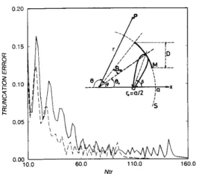
10.0 60.0 110.0 1 0.00 Ntr 0Fig. 1. A circular reflector antenna geometry and the truncation error de- pendence on the matrix order for two sample geometries: ka = 100 (dashed curve) and ka = 150 (solid curve), BO = 0, B,, = 30 degrees, kb = 9.
frequency dependences of radiated power and directivity are given and discussed showing the effect of the feed directivity and aperture dimension. Finally, principal conclusions are given in Section VII.
The time dependence e-Zwt is omitted throughout the anal- ysis.
11. FOFUWLATION
A general two-dimensional (2-D) reflector antenna geometry is shown in the inset of Fig. 1. The perfectly-conducting reflector M is a part of a circle of radius a. The reflector has zero thickness and angular width 28,, with the central point at
Bo
which is the offset angle. For a front-fed reflector, 00 = 0. The radiation pattern of the primary line source feed is characterized by using the CSP method [1]-[3]. It is known that main radiation beams of most antennas are Gaussian near the beam axis, and so the idea of analytic continuation of the real source position to the complex space has been found tobe extremely fruitful. In our structure, the source is placed at the geometrical focus, i.e., .'o (a/2)a; in real space, and its
directivity is characterized by b, so that the complex position vector becomes
The real number b is a measure of the source directivity, and
the aiming angle
p
measured from the x-axis represents the beam direction. For the front-fed reflector case ,L? = 0.Depending on the polarization, we denote by u(7) the H , or E, component of the field. The total field utot(7) can be
written as the sum of the incident
uin(3
and the scattered~""(3
fields. The incident. field due to the line source of amplitude C at the complex position r', is given bywhere IC = w / c , and H,$')(lcr) is the Hankel function of the first kind. With the use of the addition theorem for the Hankel functions, it can be written as
uin(r, Cp) =
c
J,(lcr,)H~)(lcr)ei"('P-'.), r>
I T = [
(3) 00 n=--00 where r, = drf+
2irob cosp
- b2e,
=COS-^
(4)with the condition of Re ( r , )
>
0.The complex source is a model of a radiating aperture where the aperture width is 2b [2]. Furthermore, as explained in [lo,
p. 1501, it can be thought of as a cylindrical source in real space located at d = T< with the radius
I
bl. For some geometries, thereflector surface may be in the near zone of the feed antenna, but expression (3) is valid both at near and far zone of the feed as far as T
>
lrSl is satisfied. A note should be made thatfunction (2) is an exact solution of the Helmholtz equation; this is unlike Gaussian-type exponents frequently used to represent beam waves.
To obtain the rigorous solution of the problem, the scattered field has to satisfy the Helmholtz equation, the Neumann or Dirichlet type boundary condition on the screen depending on the H- or E-polarization, the Sommerfeld radiation condition, and the Meixner condition at the reflector edges. These require- ments guarantee the uniqueness of the solution and, moreover, the existence in a certain class of functions [ l l , p. 1161 for any smooth open contour M.
The scattered fields can be expressed in integral form as a single-layer or double-layer potential over M. Then, the following equations are obtained by imposing the boundary conditions
H-Polarization
E-Polarization
-uZn(F,
2)
=jE(J)Go(.',
,)dJ; ?'EM
(6) where n' is the outer unit normal, j ~ , ~ ( 7 ) are the unknown current densities, and Go(.',,) is the 2-D Green's function (i.e., z/4Hh1)(kld-
.'I)).
Equations (5) and (6) are widely known, as well as the MOM-based solutions of them. It is worth noting that to reduce the singularity of the kernel, (5) can be transformed into a form similar to (6) [12, p. 671. Conventional MOM solutions using sub-domain triangle or pulse basis functions, however, lead to matrixes of the order N = lO(D/X) to 30(D/A). A more reasonable choice of basis functions like a series of sinusoids as in [4] may result in a much smaller matrix size, but it also drastically increases the filling time due to massive numerical integrations for matrix elements found as certain
m U Z E R et al.: ACCURATE SIMULATION OF FGFLECMR ANTENNAS 195
inner products. In general, as (6) is a Fredholm equation of the first kind, it is ill-posed, and so the convergence of direct solutions to it is not guaranteed when N + 00.
For these reasons, it is recommended to regularize (5) and (6), i.e., to convert them to the Fredholm form of the
second kind. A most straightforward way to achieve this is to make use of Tikhonov' s numerical self-regularization approach. This idea was exploited in [12] for a number of
2-D and three-dimensional (3-D) axially-symmetrical open surfaces. Here, the convergence of MOM-type algorithms is ensured. Nonetheless, all the previous remarks about the matrix size (at least lOD/A) and CPU time are valid.
The indicated problems can be overcome provided that the analytical regularization can be performed. The basic idea is extracting a certain part of the integral operator which is invertible analytically and inverting numerically the remain- ing part. Regularization ensures the existence of an exact solution and justifies application of a MOM-like numerical algorithm which is stable and has a pointwise convergence. As for the efficiency, i.e., memory requirements and CPU time, it depends on the scatterer shape which determines the matrix elements. In case of M being an open circular contour, all the matrix elements can be obtained explicitly. This procedure is equivalent to a judicious choice of basis functions in MOM-solution (as special series of trigonometric functions [7, p. 4301) possessing orthogonality, satisfying the edge condition in term-by-term manner, and allowing to take inner-product integrals analytically. If the reflector is not circular, a similar approach can be developed, but the matrix elements must be found by numerical integration. Thus, the advantages of the regularization in a circular geometry compel us to apply it to practical reflectors.
HI. &'PROXIMATION OF A PARABOLIC BY A CIRCULAR REFLECTOR
Parabolic reflector operation is based on the well-known feature of the infinite parabolic surface to focus a plane wave to a certain fixed line. By reciprocity, if a line source is placed at the focal line, the secondary field has a planar wavefront independent of the polarization. If the reflector contour is only a part of a parabola, however, then the resulting edge spillover and diffraction cause the scattered field not to be a plane wave anymore. Instead, it is a cylindrical wave, and the total pattern contains a main beam and a number of sidelobes. To decrease the effect of edges, it is preferable to increase the reflector size and to lower the amplitude of the primary field at the edges. In fact, this is the main reason for selecting a directive source as a feeder.
It is equally well-known that if the focal distance
F
of a parabolic arc is large enough with respect to the reflector aper- tureD ,
this arc may be well approximated by a circular one of the radius a = 2 F [ 131. Let us denote the axial deviation of such a circle from the parabola (i.e., the geometrical error) as A(8) Corresponding to the angular position 8. This function A monotonically increases with 8, so that the maximum deviation is achieved at the reflector upper edge where 8 =e,,
+
Bo. Further, this discrepancy between the parabola and the circleI
1 0 0 2 0 0 ka 3 0 0 m 5 M ) 6 0 0
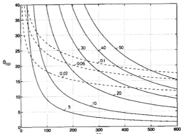
Fig. 2. Equal-value curves of the electrical error (shown in dashed lines for different values of A/X) and the reflector size (shown in solid lines for different values of D / X ) as a function of ka and flap.
can be expressed in terms of the wavelength, A/A (this error can be called the electrical error). After some algebra, we obtained a simple formula: A/A = ( k a / ~ ) sin4
+(ea,
+
80). An engineering rule-of-thumb is that the errors smaller thanA/16 = 0.06X may be neglected [14], [15]. To illustrate, Fig. 2
presents the family of equal-value curves of A/A in the plane of parameters ka and
Bap
forBo
= 0. Also, the equal-valuecurves of the front-fed aperture size D/A = (ka/.rr) sin
e,,
are presented for convenience. They indicate that the domain of validity in approximating a parabolic by a circular reflector is not restricted to electrically small reflectors. Indeed, in the case of a front-fed geometry, ife,,
= 30 degrees (a deep dish), one may take ka as much as 42.2, that isD
= 6.69Afor F / D = 0.5. If, however,
e,,
= 15 degrees (a shallow dish), the corresponding values expand to ku = 649.4 andD
= 53.5A ( F / D = 0.97). For a practical offset reflector geometry where Bo xea,,
an allowed aperture dimension is approximately half as large.IV.
BASIC EQUATIONS AND THE SYMMETRY SPLITI-ING Guided by the considerations of the previous sections, we restrict our further analysis to the circular reflectors. As the regularization procedure which will be used has been published elsewhere [7], [8], we shall omit the details. Instead, we shall concentrate on transforming the equation in a form suitable for an efficient numerical implementation. This is achieved by splitting the resulting matrix equations into two sets of equations corresponding to even and odd parts of the surface current.First, we discretize the integral equations (5) and (6) and reduce them to the series equations. Thus, for a circular contour
M
the surface current densities are assumed to be zero on the rest of the circle (S) and expanded in terms of a series of angular functions with coefficientsz,H,~,
as follows196 IEEE TRANSACTIONS ON ANTENNAS AND PROPAGATION, VOL. 43, NO. 8, AUGUST 1995
where a~ = l / k and Q I E = 1 to account for the differentiation
in (5). Similarly, using the addition theorem the Green's function can be expressed in terms of a series of angular exponents. Then, substituting all the functions into (5) and (6), applying the boundary conditions over M, and taking account of the absence of the current on S, one obtains the following dual series equations
-00 -00 n=--00 M n=-m where
w,"
( k a ) = J:, (ka)H?)' ( k a ) W , E ( k a ) = J,(ka)H?)(ka) bf = J n ( kr,)Hil)' ( ka)e-ines bf = J n ( k r , ) H ~ l ) ( k a ) e - i n e sand the prime denotes the derivative with respect to the argument.
One can solve these dual series equations using the point- matching method [ 161. As we have noted previously, however, that approach leads to an ill-posed equation set having no proof of universal convergence. Instead, we extract a canonical form from the dual series equations which can be converted into a Riemann-Hilbert Problem [5]-[9]. Then, the analytical solution of the latter leads to a regularized infinite algebraic equation system of the Fredholm second kind differing from the plane-wave excitation case [6]-[9] only by the right- hand part. In terms of the integral equations (5) and (6), this procedure is equivalent to extracting and inverting the logarithmic part of the kernel function (see (51) in [7], and (27) in [SI, as well as (9) in [9]). The equation sets obtained have summations going from -cc to +W. After truncation at the term Nt,, they will have the order 2Nt,
+
1. To reduce the computation time, each of them can be split into two independent half-size equations. This is done by decomposing the problem into even and odd parts with respect to the symmetry axis of reflector. Indeed, introducing the even and odd expansion coefficients asand substituting (14) into matrix equations, one obtains
for m = (0)1,2,
...,
and the term in parenthesis in the summation index exists only for the even case. In (15)where
ZEA,' = T,", f Tfmn, Z E z = TE mn f TE -mn and
Here, 6, is defined as one if n = 0, otherwise two. Other coefficients, T,", = Tmn(cos f l a p ) , TEn = Tmn( - cos
e,,),
and the functions A:, A:, Tmn, A&, and A E n are defined in the Appendix.When solving a matrix equation, the CPU time is not a linear function of the matrix order. Therefore, the reduction to two half-size equation sets saves the CPU time especially for large matrixes, and it also avoids the inaccuracies resulting from the possible round-off errors.
Note that in (15), the right-hand parts have infinite summations that may lead to a certain truncation error in practical computations. The selection of new unknowns as =
lgmAf&,)?*
+ ir(ka)2b2even/odd andriEnE)'*
= Sm J: ( k a ) H i ) ( k a ) A: aFnE)'*+
ImI
bZevenloddmodifies (15) to a form which enables one to minimize the truncation error in the right hand part. Eventually, any of the obtained equations can be written in the following operator notation
(20) where I is the identity operator, and all the operators are compact in the Hilbert space of infinite sequences, 12 (i.e.,
with finite sum of squared absolute values of coefficients, see [7, p. 4301). Hence, any of the operators I -
A
is of the Fredholm second kind in Z2, and so Fredholm's theorems are valid (provided that the right-hand part also belongs to Z2); then the unique solution 7 exists in Z2. Large-index estimates for cylindrical functions show thatB
E 12 if lrsl<
a resulting in a restriction a > 2 b / f i for in-focus primary line source. Furthermore, the approximate solution may be obtained with&UZER et al.: ACCURATE SIMULATION OF FEFLECYDR ANTENNAS 797 any desired accuracy via truncation to a finite order N,, as the
uniform pointwise convergence to exact solution is guaranteed for N,, + 00. As a rule-of-thumb, for a d-digit accuracy in
the far-field prediction, one has to take N,,. = ku
+
(d-
1 ) 2 (see Fig. 2 of [9]).V. FAR-FIELD CHARACTEMS~CS
The radiation pattern of the primary source is obtained from (2) or (3) by using large-kr asymptotic expansions of the Hankel functions. Similarly, one obtains the total field radiation pattern in the presence of the reflector as
where gn =
Jn(kr,)e-ines
+yn, and yn is taken as x ~ J ~ ( k u ) or x f J n ( k u ) depending on the H- or E-polarization, respec- tively.For the reflector antenna geometries, an important parameter is the total radiated power P normalized to the radiated power Po of the complex line source in free space.
PO
is easily found by integrating the squared absolute value of function (2) over the circle of a large enough radiusklF-
r<l>>
1 and is given byTABLE I
CPU TIMES OF THE COMPUTER CODES
I e.. ~I = 300 .. I1 E-POL ~~ ~~ I H-POL1 ~~~ ~~
ka = 62.8(0 = lOA), Nt, = 70 11 4 seconds I 4 seconds
ka = 125.6(0 = %A), Nt, = 130 11 11 seconds I 12 seconds
ka = 188.4(0 = 30A), Nt, = 195 11 28 seconds I 26 seconds
I
0 30 60 90 120 150 180
THETA ( DEG )
Fig. 3. Comparison of E-case radiation pattem of a parabolic reflector from [2] ( F / D = 0 . 9 6 , D = 1OX) using UTD and AI with a circular one (ka = 121.38, 6Jap = 15 degrees, and D = 1OX) calculated with the present method. Feed directivity parameter, kb = 9.06 corresponds to a -10 dB edge illumination.
VI. NUMERICAL RESULTS AND DISCUSSION (22)
Po = C2--1,(2kb) 277
IC
where 77 is (ZO)-' and 20 for E and H-polarization cases, respectively. 20 is the intrinsic impedance of free space, and Io is the modified Bessel function of order zero.
Note that PO increases with kb rapidly as e z k b / & 6 . By following the formulation of Section 11, the expression for PIPo is obtained as follows
-
mThe directivity
D
in the main beam direction( 4
= T ) is readily obtained asn=--00
The frequency dependence of PIP0 and
D
is important in designing the narrow beam reflector antennas for pulse power transmission and wide-band communications. The directivity should be compared to the prime feed directivity, Do, in the source beam direction(4
=p)
which is easily found asThe ratio
D/Do
shows the efficiency of the reflector as a directivity transformer.In this section, the normalized radiation patterns of some reflector antennas are obtained for various aperture dimensions and feed directivities, and some properties of reflector antennas are discussed through the results. Although the exploited regularization procedure was equally efficient for any an- gular width 20ap and offset angle 00, we shall restrict the numerical analysis mainly to the reflectors meeting the good approximation criterion A(Oap
+
60)5
0.06X as discussed in Section III.All the computations were performed by taking the matrix truncation number N,,. equal to the integer value of (ka
+
10) which guarantees an accuracy of 0.001 in calculating the far field. This is demonstrated in Fig. 1 by the behavior of trunca- tion error E, = max Ix?v+l - x N i rI/
max1x271
as a function of the matrix order N t T . It is worth noting that such a test is also useful for debugging a computer program. In addition to accuracy, computation time is another measure of efficiency in a numerical method. Table I presents the computation times for different aperture dimensions. The results are from a SUN SPARCStation 2 (4 MFLOPS). Thus, 11-12 seconds of CPU operation here, for a 20-A scatterer, is comparable to the CPU times of the CRAY X-MP supercomputer for a MoM- based solution as was reported in [4]. According to [17], a CRAY X-MP can operate 50-200 times faster than this workstation.For the validation of the results, we have checked the CSP solution in the limiting case corresponding to the real source point excitation. Further, in Fig. 3, the high-frequency solution of Suedan and Jull[2] (synthesized from AI and uniform GTD
798
-30.0
B
-50.0
IEEE TRANSACTIONS ON ANTENNAS AND PROPAGATION, VOL. 43, NO. 8, AUGUST 1995
- - -10.0 -30.0
B
-50.0 -70.0 0.0 -20.08
-40.0 -60.0 I 1 60.0 120.0 180.0 THETA(DEG) (a) -120.0 -60.0 0.0 60.0 120.0 180.0 TUETA(DEG) (b)Fig. 4. Comparison of E- and H-case radiation pattems for (a) front-fed
and (b) offset circular reflector of ka = 121.38, Oap = 15 degrees. Feed parameter is kb = 9.06 (-10 dB edge illumination). In (b), the offset and the feed aiming angles are 00 = 22 degrees and = 41.25 degrees, respectively.
results for a CSP as front feeder) is compared with our circular reflector patterns for D = 1OX. To obtain better agreement in the regions at the back of the reflector, the edge tangents of the parabolic and circular reflectors are equalized by adjusting the angular width of the circular reflector. For this geometry, the electrical error is 0.001 1 A, and the deviation between two patterns is smaller than 1 dB.
Fig. 4(a) and (b) demonstrates the comparison of E- and H- polarization cases, for front-fed and offset reflector antennas, respectively, having the aperture of D M 1OX and
-
10 dB edge illumination. It is seen that the rear sidelobe levels are higher in H-polarization. This is expected since the edge effects are stronger due to transversal flow of the surface current. In Fig. 4(b), there is also a few degrees shift at the main beam location (boresight error) of the offset antenna due to a nonsymmetrical excitation. and a circular aberration.The effect of the source directivity for both E- and H- polarizations is examined in Fig. 5(a) and (b) for a D = 1OX reflector. Source directivity is increased with increasing
-10.0 -30.0
8
-50.0 -70.0 ( €-Polarization ) 50.0 100.0 150.0 TUETA(DEG) (a) U-Polarization\
- !&=3.5 I 0.0 50.0 100.0 150.0 -70.0'
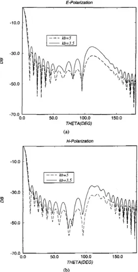
TUETA(DEG) (b)Fig. 5. Effect of the different source directivities for (a) E-polarization case and (b) H-polarization case. Front-fed reflector paramaters are ka = 62.8 and Bap = 30 degrees ( D =
lox,
F / D = 0.5). Feed directivity parameters, kb = 3.5 and kb = 5 correspond to - 13.29 dB and - 18.50 dB edge illuminations, respectively.parameter kb, and the results show that all the sidelobe levels are decreased while the main beam width changes little for constant electrical dimensions of the reflector. Fig. 6(a) and (b) shows the radiation pattems in E- and H-polarization cases for two reflector dimensions, D = 1OX and 20X. It is seen that the main beam is narrower for a larger aperture, and the sidelobe level is reduced except for the spillover sidelobe which is the same due to the same edge illumination.
We would like to emphasize that the truly new point in all the above results is that they are uniformly correct with a 0.001 accuracy. This ensures an equally accurate computation of the important antenna characteristics such as the radiated power and the directivity.
Fig. 7 presents the plots of the ratio PIP0 as the aperture dimension of the reflector increases. The variation of PIP0 around unity is within 7% and caused by the in-phase or out-
&UZER et al.: ACCURATE SIMULATION OF REFLECTOR ANTENNAS 0 9 0 199
t
/ €-Polarization 0.0 -20.0g
-40.0 -60.0 50.0 100.0 150.0 -80.0 0.0 -10.0 -30.08
-50.0 -70.0 THETA(DEG) (a) H- PolarizationI
Y'
50.0 100.0 150.0 THETA(DEG) 0)Fig. 6. Effect of the different aperture dimensions for (a) E-polarization case and (b) H-polarization case. Front-fed reflector angular halfwidth is Oap =
30 degrees ( F / D = 0.5). Feed directivity parameter kb = 5 provides
-
18.50 dB edge illumination.of-phase interference of the weak edge-diffracted field with a stronger reflected field. Besides, the oscillation levels are higher in H-polarization because of the stronger edge effects. Fig. 8 shows the directivity variation for the same conditions. It is seen that there is a slightly oscillatory linear increase in the directivity for increasing aperture dimension for the same reason as above (we are thankful to one of the reviewers for drawing out attention to this fact). Note that the primary feed directivity here is only
D O
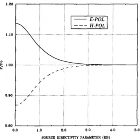
= 4.1 1. As expected, increasing source directivity reduces the edge effects so that the variations in PIP0 decrease rapidly (see Fig. 9). For a practical case, the edge illumination can be taken as 9dB
below the center of the reflector, then PIP0 = 1 with 0.001 accuracy. Similarly, increasing the feed directivity increases the directive gain, since the diffraction effect is reduced. Finally, Fig. 10 presents the variations of overall directivity D and feed directivityD o
with
kb.
1.0 2.0 3.0 4.0 5.0
0.901 ' ' ' ' ' ' '
'
APERTURE DlMENSlON (Dflambda)
Fig. 7. Total radiated power variation with the increasing aperture dimension
for Bap = 15 degrees ( F / D = 0.97) and kb = 1.5.
20.0 15.0
6
10.03
5.0 0.0, I I 2.0 3.0 4.0 5.0 APERTURE DIMENSION (D/lfimbdn)Fig. 8. Directivity variation with the increasing aperture dimension for
Bap = 15 degrees ( F / D = 0.97) and feed directivity parameter kb = 1.5.
1.20 I . . . , . . 1.10 0 . _ _ - .
e
1.00 ..._.._... : ... .... :...-.. , - ... 2_ _
.< % [ :. ,I j 0.80 0.0 I .o 2.0 3.0 4.0 5.0SOURCE DIRECTIVITY PARAMETER (KB)
Fig. 9. Total radiated power variation with the increasing feed parameter kb for Oap = 15 degrees and k a = 50(D/X = 4.1, F / D = 0.97).
800 EEE TRANSACTIONS ON ANTENNAS AND PROPAGATION, VOL. 43, NO. 8, AUGUST 1995
120.0
SOURCE DlRECTlVlTY PARAMETER (KB)
Fig. 10.
B a p = 30 degrees and ka =62.8 ( D =
lox,
F / D = 0.5).Directivity variation with the increasing feed parameter kb for
VII. CONCLUSIONS
The dual series formalism is used in combination with the complex source point approach to analyze the cylindrical reflector antennas via the method of regularization. By the present method, the principal results of the reflector antennas are verified and compared to the high-frequency approximate solutions available for 2-D parabolic reflectors. As this ap- proach is numerically exact within the adopted model, it can be used to analyze accurately the further properties of reflector antennas like the focal shift [18], front-to-back ratio [19], and others. In addition, one can use the presented data as a benchmark to check the accuracy of the other numerical codes and approximate techniques. Also, it is worth mentioning that a similar approach can be used to simulate 3-D spherical reflectors, however, the regularization procedure is based on another analytical technique [20], [21].
This approach also overcomes the difficulty in applying the CSP method for diffraction by curved scatterers with edges, where ray tracing is used. Indeed, then the reflection points are in complex space, and the edge diffraction points are in real space so that there are difficulties in including both. The authors are thankful to one of the reviewers for this consideration.
APPENDIX
The functions appearing in the solution for H- and E-cases are as follows
AEn = Af(ku)T& (26)
For In1
>
Ica+
5, both A: and A: go to zero as O(1nl-l)with In1 + 00 [7]. Also
where S m n ( z ) are defined via Legendre’s polynomials P n ( z ) as
If n = m, L’Hospital’s rule reduces (3 1) to the following form
Iml
where U o ( z ) = l , V l ( z ) = -z,...,V,(z) = P,(z)
-
For 1721, Iml + 00 all the functions Tm, decay as O(lm - 2zP,-1(2)+
Pn-2(2).n
+
ll-11mnl-(1/2)) uniformly for any Bap#
0 or T [71. ACKNOWLEDGMENTThe authors are indebted to Prof. E. V. Jull for encourage- ment and to the reviewers for improving the manuscript.
REFERENCES
[l] G. A. Suedan and E. V. Jull, “Beam diffraction by a half-plane and a wide slit,” IEEE Trans. Antennas Propagat., vol. AP-35, pp. 1077-1083,
Sep. 1987.
[2] -, “Beam diffraction by planar and parabolic reflectors,” IEEE
Trans. Antennas Propagat., vol. 39, pp. 521-527, Apr. 1991. [3] L. B. Felsen, “Complex source point solutions of the field equations and
their relation to the propagation and scattering of Gaussian beams,’’ in
Symp. Math., vol. 18, pp. 39-56, 1975.
[4] M. R. Barclay and W. V. T. Rusch, “Moment-method analysis of large, axially symmetric reflector antennas using entire-domain functions,”
IEEE Trans. Antennas Propagat., vol. 39, pp. 491496, Apr. 1991. [5] Z. S. Agranovich, V. A. Marchenko, and V. P. Shestopalov, “Diffraction
of a plane electromagnetic wave from plane metallic lattices,” Soviet
Physics-Tech. Physics, Engl. Transl.. vol. 7, no. 4, pp. 277-286, 1963.
[6] R. W. Ziolkowski, “N-series problems and the coupling of electromag- netic waves to apertures: A Riemann-Hilbert approach,” SIAM J. Appl.
Math., vol. 16, pp. 358-378, 1985.
[7] A. I. Nosich, “Green’s functiondual series approach in wave scattering by combined resonant scatterers,” in Analytical and Numerical Methods
in EM Wave Theory, M. Hashimoto, M. Idemen, and 0. A. Tretyakov, Eds. Tokyo: Science House, 1993, pp. 419469.
[8] D. Colak, A. I. Nosich, and A. Altintas, “RCS study of cylindrical CBA with outer or inner material coating: The case of E-polarization,” ZEEE
Trans. Antennas Propagat., vol. 41, pp. 1551-1559, Nov. 1993. [9] -, “RCS study of cylindrical CBA with inner or outer material
coating: The case of H-polarization,” IEEE Trans. Antennas Propagat., vol. 43, no. 5, pp. 440-448, May 1995.
[lo] I. V. Lindell, Methods for Electromagnetic Field Analysis. Oxford Claredon Press, 1992.
[ l l ] V. I. Dmi$ev and Y. V. Zakharov, Integral Equations in Electromag-
netic Boundary Value Problems. Moscow: Moscow Univ. Press, 1987 (in Russian).
[12] Y. V. Zakharov and Y. V. Pimenov, Numerical Methods in Radio Wave
Diffraction..
[13] W. L. Stutzman and G. A. Thiele, Antenna Theory and Design. New York Wiley, 1981.
OGUZER et ai. : ACCURATE SIMULATION OF REFLECTOR ANTENNAS 801
J. D. Kraus, Antennas.
T. Lee, R. C. Rudduck, and M. C. Bailey, “A surface distortion analysis applied to the hoopkolumn deployable mesh reflector antenna,” IEEE
Trans. Antennas Propagat.. vol. 37, pp. 452459, Apr. 1989. H. A. Kalhor, “Electromagnetic scattering by a dielectric slab loaded with a periodic array of strips over a ground plane,” IEEE Trans.
Antennas Propagat., vol. 36, pp. 147-151, Jan. 1988.
J. J. Dongama, “Performance of various computers using standard linear equations software,” Supercomputing Rev., Jan. 1990, pp. 73-80. H. Ling, S.-W. Lee, P. T. C. Lam, and W. V. T. Rusch, “Focal shifts in parabolic reflectors,” IEEE Trans. Antennas Propagat., vol. AP-33, pp. 744748, July 1985.
M. S. Narasimhan and K. R. Govind, “Front-to-back ratio of paraboloidal reflectors,” IEEE Trans. Antennas Propagat., vol. 39, pp. 877-882, July 1991.
S. S. Vinogradov, “Reflectivity of a spherical shield,” Radiophysics
Quantum Electronics, Engl. Transl., vol. 26, no. 1, pp. 78-88, 1983. R. W. Ziolkowski and W. A. Johnson, “Electromagnetic scattering of an arbitrary plane wave from a spherical shell with a circular aperture,”
J. Math. Physics, vol. 28, no 6, pp. 1293-1314, 1987.
New York: McGraw-Hill, 1988.
Taner O b z e r was bom in Trabzon, Turkey, in 1967. He received the B.S. degree in electrical engineering from the Middle East Technical Uni- versity, in 1989 and the M.S. degree in electrical and electronics engineering from Bilkent University, Ankara, Turkey in 199 1.
Currently, he is a Research Assistant at Bilkent University studying as a Ph.D. student. His research interest is electromagnetic field theory.
Ayhan Altinhq (S’82-M’8&SM’93) was bom on March 29,1958, in Turkey. He has received the B.S. and M.S. degrees from the Middle East Technical University (METU), Ankara, Turkey, in 1979 and 1981, respectively, and the Ph.D. degree from The Ohio State University, Columbus, in 1986, all in electrical engineering.
From 1981-1987, he was with the ElectroScience Laboratory of The Ohio State University. Currently, he is an Associate Professor at the Department of Electrical and Electronics Engineering, Bilkent University, Ankara, Turkey. His research interests include electromagnetic radiation and scattering, microwaves, fiber optics, and integrated optics.
Dr. Altinta? is a member of Sigma Xi and Phi Kappa Phi. He is the recipient of the ElectroScience Laboratory Outstanding Dissertation Award of 1986, IEEE 1991 Outstanding Student Branch Counselor Award, and the 1991 Research Award of Prof. Mustafa N. Parlar Foundation of METU.
Alexander I. Nosich (M’94-SM’95) was born in 1953 in Kharkov, Ukraine. He graduated from the Radio Physics Department of Kharkov University in 1975. He received the Ph.D. and D.Sc. degrees in radio physics from Kharkov University, in 1979 and 1990, respectively.
Since 1978, he has been with the Electronics Department of the Institute of Radiophysics and Electronics (IRE) of the Ukranian Academy of Sciences, Kharkov, as a Junior and Senior Research Scientist. From February to August 1992, he was with the Department of Electrical and Electronics Engineering of Bilkent University, Ankara, Turkey, as a Visiting Professor through the Fellowship of Turkish Scientific and Technical Research Council W B I T A K ) . From October 1992-March 1994, he was with the Department of Electrical Engineering and Computer Science of Kumamoto University, Japan, as a Guest Scientist through the Fellowship of Matsumae International Foundation, and an Associate Professor. Currently, he is a Leading Scientist at the IRE, Kharkov. His research interests include free space and open waveguide scattering, complex modes behavior, radar cross-section modifying, and antenna simulation.