Reflection coefficient null of acoustic waves at a liquid-anisotropic-
solid interface
Orhan Ankan
Electrical Engineering Department, University of lllinois at Urbana-Champaign, Urbana, Illinois 61801 Emre Telatar
Electrical Engineering Department, Massachusetts Institute of Technology, Cambridge, Massachusetts 02139 Abdullah Atalar
Electrical and Electronics Engineering Department, Bilkent University, Ankara, Turkey (Received 2 February 1988; accepted for publication 22 August 1988)
The reflection coefficient of acoustic waves incident on a liquid-solid interface from the liquid side is numerically calculated for a general anisotropic solid oriented in any arbitrary direction. The reflection coefficient depends, in general, on polar and azimuthal angles of incidence.
Results are presented for various crystalline materials of different symmetry classes. A null in
the reflection coefficient amplitude is detected at a particular incidence angle for every
anisotropic material that supports pseudosurface waves. The null in the reflection corresponds
to the
excitation
of the
pseudosurface
wave
on the
interface
surface,
a•nd
it has
typically
a very
narrow
angular
aperture.
The
angular
position
of the
null
is very
critical
and
highly
dependent
on the elastic parameters of the anisotropic solid.PACS numbers: 43.20. Fn, 43.35.Cg
INTRODUCTION
Although the reflection-refraction problem at a liquid-
isotopic-solid interface has been intensively studied, •-3 the
reflection-refraction problem at a liquid-anisotropic-solid interface remains relatively untouched because of the in- creasing complexity of analytic expressions and numerical difficulties. The theoretical aspects of the reflection-refrac- tion problem between two anisotropic solids were reviewed
by Henneke 4 with a discussion on critical-angle phenome- na. 5 Some numerical calculations for special cases were giv- en by Auld. 6 Jones and Henneke 7 gave a numerical solution
for reflection of elastic waves from a stress-free boundary in
an anisotropic half-space. Atalar 8 presented the numerical
solution of the reflection coefficient at a liquid-cubic-solid
interface. Somekh et al. 9 have studied the reflection coeffi-
cient of anisotropic materials at a liquid interface for the purpose of understanding acoustic images obtained by acoustic microscopes. They have numerically calculated the reflection coefficients for some materials and applied the re- sults for the interpretation of contrast in acoustic images.
Crean and Waintal•ø have calculated the Rayleigh wave ve-
locity on anisotropic substrates for the same purpose. Ve-
lasco and Garcia-Moliner TM have given a Green's function
analysis to calculate surface waves in anisotropic cubic crys-
tals. Rokhlin eta/. •2'•3 have calculated the reflection and
refraction of elastic waves at the planar interface of two gen- erally anisotropic solids.
In this article, the results of a study on the reflection of plane acoustical waves at a planar liquid-anisotropic solid interface are presented. The solution is for the most general case, that is, the anisotropic solid can be of any symmetry
class and the interface surface could be selected as any de- sired plane of the crystal.
I. CALCULATION OF THE REFLECTION COEFFICIENT
In this section, the acoustical wave equation and the
plane-wave solutions in anisotropic media will be consid-
ered, the boundary conditions will be examined, and a solu- tion method for the reflection-refraction problem at a liq- uid-anisotropic-solid interface will be derived. For
simplicity, acoustical attenuation and piezoelectricity of
both media are neglected. Both media are assumed to be of
infinite extent and the interface is assumed to be an infinite
plane. Due to the complexity of the expressions, an analyti-
cal solution is not possible, hence, a numerical approach is
attempted. The analytic expressions will be abandoned only
at the point where no more analytical manipulations are pos-
sible. The remaining part of the problem will be solved by
numerical means. Although this derivation may be found
elsewhere, 4 we will give it for the sake of completeness and to
bring clarity to notation.
Following
the notation
of Auld,
6 consider
the acoustic
field equations and the constitutive relations in a nonpiezo-electric material:
r32u
S=Vsu,
T=e:S,
V.T=p
o9t2
--F'
(1)
where S, T, and e are the strain, stress, and stiffness constant matrices, respectively, in the abbreviated subscript notation. With this notation, S and T become 6 by 1 matrices and e becomes a 6 by 6 matrix with, in general, 21 independent constants, u and F vectors represent the particle displace-
ment and the body force field in the material, p is the density
of the material, Vs is the symmetric gradient operator, and V. is the divergence operator. The latter are given by
VS •
•
o
o
•xo
o
o o
o
o ax
o ay ax i LIQUID C 0 ,•0 = (V') r ß Cn ... C 66, .P ANISOTROPIC SOLIDSince for a freely vibrating medium the body force F is zero, the three equations of Eq. ( 1 ) may be combined to give
c• 2u
(V'c:Vs)u = • (2)
c•t 2 '
which is a wave equation. The wave equation can be solved analytically only for a limited number of cases. The simplest
case involves the plane-wave solution. If we introduce the phasor notation for plane waves, we can write the solution
for the particle displacement field as
u=Re{Aa exp
L/(wt- k.r)]),
where ,4 is the amplitude of the plane wave, a is the unit
polarization vector of the plane wave, w is the angular fre- quency, k is the wave vector pointing in the propagation
direction, and r is the position vector. With exp(jot) time
dependence, we may replace the operator c•/c•x• with -jk• and d/dt by jw. Then, the symmetric gradient operator is
reduced to k• o o 0 0 o o kz
o
kz
kz 0k•, k•, 0
= -jk m l L o oo
o
o o l•o
b
lz o Lco_
where
lx, ly, and lz are the direction
cosines
of k. With the
definition V• = (v.)T= --jkL, Eq. (2) becomes
-- k :LTcLa
= -- pw:a
or[ k :LTcL -- pto:I ] a = 0,
(3)
where I is the third-order identity matrix. The matrix LTcLis called
the Christoffel
matrix
and
is denoted
by U (1•,,
1•,,
lz ).
Note that the Christoffel matrix depends only on the stiff- ness constants and the propagation direction. Equation (3)
is called
the Christoffel
equation.
6 To obtain
nontrivial
solu-
tions for a in Eq. (3), the determinant must be zero:
I k 2r -- Pco2II
= O.
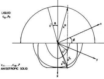
FIG. 1. Scattering geometry suitable for the liquid-anisotropic-solid reflec- tion problem. Wave vectors along with slowness surfaces are shown. Inter- face is the x-y plane.
Hence,
we see
thatpco2/k
• are
the eigenvalues
ofr and
a is an
eigenvector of r. We observe that, since r is a 3 by 3 matrix, in general, there exist three different solutions for k and a, corresponding to the same direction of propagation, which implies the existence of three different wave modes propa- gating in the same direction with different polarization vec-tors and velocities. Moreover, since r is symmetric, the po- larization vectors corresponding to distinct k values are
orthogonal. Also, Eq. (3) can be described entirely by the
variable k/w, which is called slowness. The slowness surfaces are defined to be the loci of the end points of the vector k/w,
and they prove to be useful in the solution of the reflection-
refraction
problem.
6
We now consider the reflection-refraction problem de- picted in Fig. 1. The boundary between the liquid medium and the anisotropic solid is the x-y plane. We assume a unit amplitude plane wave striking the interface with an angle 0
and with a wave vector k I. The angle between the plane of
incidence and the x axis is •. We write the particle displace- ment field of the incident wave in phasor form with exp(jot) time dependence suppressed as
U I = (kI/ko)exp( --j kI.r),
where ko is the wavenumber in the liquid. Since the incident medium is liquid, the only reflected mode is a longitudinal wave. On the other hand, in the anisotropic solid there can be three refracted modes: One quasilongitudinal (QL) and two quasishear (QS) waves. The corresponding particle dis- placement fields can be written as
u • = R (k•/ko)exp( --j k•.r), u L = La L exp ( -- j kL.r), uS'= S•a s' exp( --j kS'.r), u s-' = S2 as'- exp ( -- j kS:.r),
where k •, k L, k s', k s-' and R, L, S•, S: are the wave vectors
and the complex amplitudes of the reflected wave in the liq- uid and of the QL and two QS waves in the solid, respective-
ly. Here, a L, a s', and a s-' stand for the unit polarization vec-
tors of the refracted waves.
The boundary conditions at the interface can be stated as follows. Since the liquid moves parallel to the interface plane freely, the condition for particle displacement continu- ity holds only for the normal component of u:
u'fi = u"fi,
where u and u' are the particle displacements in the liquid and in the solid, respectively, and fi is the unit normal vector of the interface. This boundary condition gives
I R L S• S
(Uz + uz )lz:o = (Uz + Uz + Uz:)lz=O, (4)
where Uz is the z component of the particle displacement and the superscripts denote the type of the wave as before. The second set of boundary conditions arise from dynamical con-
straints:
T.fi = T'.fi,
where T and T' are the respective stress tensors of the two media. From this boundary condition, we find
(T3+T3 •) z:o=(T•+T•S'+T•S2)lz_- o, ar=3,4,5,
(5)
where the stress components are shown in abbreviated sub- script notation.
An implication of Eq. (4) is the conservation of the phase velocity parallel to the boundary:
kXfi = k'Xfi,
or
k z --kR=kL=kS,=kS2=lx
x x x x xk
O,I
R
L= kS,= kS2 lyko
'
ky =ky =ky
y
y =
which is also known as Snell's law. Although Snell's law
determines readily the x and y components for the wave vec-
tors of reflected
(k R) and refracted
longitudinal
(k •'), and
shear
(k s', k s•} modes,
the z components
of wave
vectors
and, hence, the propagation directions are more difficult to
ascertain.
For this purpose, the Christoffel equation should be modified for the solution of kz. The Christoffel equation may be rewritten as:
o
o
o
az a,
o
o [ci;l
o
o
kx 0 00
ky 0
o o kz0
kz ky
k z 0 kxky k,,
0
-- pco2I
=o, (6)which leads in general to a sixth-order equation in kz. Equa- tion (6) can be written explicitly as follows:
--p3c06
+p2co4(h•
+ h2 + h3)
-- pco
2 ( h ,h2 + h2h3
+ h3h
, - h • - h 2•
_ h • )
+ h,h2h3
+ 2h4hsh6
- h,h 24
- h2h
• - h3h
} = 0, (7)
whereh i = ai k2 + bik z + Ci, i = 1,..,6,
Z ø and a 1 = C55, a 2 = C44 , a 3 = C33 , a 4 = C34 , a 5 • c35 , a 6 = C45 ,b• = 2(c•5k• + c56ky
),
b 2 = 2 (c46kx
D
I- c24ky
),
b 3 = 2 (c35k•
+ c34ky
),
b
4 = (c36
-3-
c45)k
x q- (c23
-3-
c44)ky
,
b5 = (css
+ C13)kx
-•- (C45
-3-
c36)ky
,
b 6 = (c•4
+ c56)kx
+ (c46
+ c25)ky,
Cl Cllk2=
x + C66
k y + 2c16kx
2my,
2C2
__
c66k
2 q_
xc22k
y q- 2c26kx
my
, 2C
3: c55k
2 + c44k
xy _•_
2c45k•,ky
, 2C4
__
c56k
2 q- c24k
xy q- (c25
_3_
c46)kxky
, 2C5
= Clsk
2 q- c46k
xy q- (c14
q- c56)kxky
'
2C6
•. c16k
x2 + c26k
Y q- (C66
q- ci2)k•,ky
øThe above-mentioned boundary conditions are not suf- ficient for the correct solution of the problem. Another set of conditions is necessary to make sure that the nonevanescent refracted modes carry energy into the solid medium and the evanescent modes decay into the solid medium as a function of depth. The k vector direction is not a correct measure of the energy propagation direction, instead the direction of
Poynting vector P should be considered. 4 For a refracted
mode solution to be a valid one, its Poynting vector must be directed into the solid. This vector does not generally coin- cide with the normal to the wave front in anisotropic media, but it is in the direction of the gradient of the slowness sur- face. In our case, with anisotropic media at the positive z region, the z component of the Poynting vector is the only component that is important. In phasor notation, this com- ponent is given by
= - ( rs + T4 + r3 ) , (8)
where v•"s are the conjugates of the respective particle veloc- ities. For nonevanescent modes, Pz must have a positive real part in order to have a power flow with a positive component in the z direction. For evanescent modes, it has to have a negative imaginary part to get a wave that cannot carry any energy and that vanishes as z approaches infinity. With these constraints, the six solutions found for kz from the previous part are reduced to three. Note that there are exactly three kz's satisfying the Pz conditions.
The solution algorithm may be given as follows: Given the stiffness constants of the solid and the angle of incidence, the sixth-order equation in terms of kz is constructed using Eq. (7). This equation can be solved by numerical means for kz, resulting in the six kz values that are not necessarily dis- tinct. Then Eq. (3) is contructed and the normalized polar-
ization vectors (a •', a s', as'-), are found. For each of these
kz's and the corresponding polarization vectors, the z com- ponents of the Poynting vector, is calculated by-Eq. (8). The roots that have P vectors pointing to the liquid media or those leading to exponentially growing waves should be omitted.
Knowing the wave vectors and unit polarizations of all
reflected and refracted modes, the four boundary conditions may be written in terms of the unknown amplitudes, R, L,
S•, and S2. From these four linear equations [Eqs. (4) and
(5) ], the unknown amplitudes of the reflected and refracted modes can be solved.
There may be numerical difficulties for angles near the
normal incidence and near the critical angles where the
problem becomes ill-conditioned. Special precautions must
be taken for such cases to obtain the correct numerical re-
sults. These include the ordering of roots, and reducing the
degree of the equations to be solved if roots are very close to
each other.
II. RESULTS
A FORTRAN program was developed to carry out the numerical calculations necessary for the evaluation of the reflection coefficient R. The program can handle materials with arbitrary stiffness matrices of 21 constants, so materials with arbitrary orientation can be handled with proper trans-
0.8 '" 0.6 0.4 0.;) I 0 0.1 0.2 0.:5 0.4 s•nO 11 -11'12
FIG. 2. Reflection coefficient amplitude and phase at a H20-Si (011 ) inter- face as a function of incidence angle for azimuthal angles of 0 ø (dotted), 44.81 ø (solid), and 90 ø (dashed). The constants for H20 are c• = 2.277E9 and p = 1000. I IRI 0.8 0.6 0.4 0 0.2 0.4 0.6 sin 0 .•/2 0 -7/2 -ff
FIG. 3. Reflection coefficient amplitude and phase at a H•O-quartz (001) interface as a function of incidence angle for azimuthal angles of 0* (dot-
ted), 17.91 ø (solid), and 30 ø (dashed).
formation of the stiffness matrix by multiplication with the
Bond matrices. 6 The program was tested against the materi-
als whose reflection coefficients were previously calculat- ed. 8'9 The results were consistent with those previous calcu- lations within the expected precision which was about 0.1%. Obviously, these tests do not prove that the program works
correctly for all cases, nevertheless running a number of dif-
ferent cases assured us that the program is reliable.
In Fig. 2, the reflection
coefficient
R, amplitude,
and
phase
at the H20-Si interface
for the (011
) plane
of Si are
shown as a function of sin 0 for •b = 0 ø, 44.81 ø, and 90 ø. Here,
0 and
•b are the sperical
coordinates
(polar
and azimuthal
angles,
respectively)
where
•b
is the angle
between
the inci-
dence
plane
and the [100] axis. Concentrating
on the
•b
= 44.81
ø curve
in the
figure,
we can
identify
the
following
regions:
for sin
0 < 0.1622
all three
wave
modes,
namely
one
QL and two QS waves,
propagate
into the solid,
and the
reflection coefficient is approximately constant. Above
sin 0 = 0.1622
the QL wave can no longer
be excited,
and
until sin 0 = 0.2857 only two QS waves
are present.
While
sin 0 is between 0.2857 and 0.3059, only one QS wave isexcited. At sin 0 = 0.3016 there is a minimum in the reflec- 4 J. Acoust. Soc. Am., Vol. 85, No. 1, January 1989 Ankan et aL' Reflection coefficient null 4
tion coefficient. Note that, for such an incidence angle, more than 94% of the incident energy is transmitted into the solid. We also observe that, for sin 0 = 0.3159, there is a transition in the phase of the reflection coefficient corresponding to a Rayleigh wave excitation.
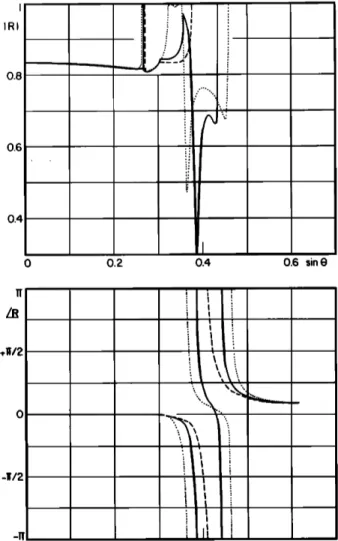
In Fig. 3, the reflection coefficient versus sin 0 plots for the H20-quartz (001) interface for 0• = 0ø, 17-91ø, and 30 ø are shown. Focusing on the 0• = 17.91 ø curve, we observe a phase transition at sin 0 = 0.3848. The reflection coefficient amplitude has a minimum value of 0.2950 at sin 0 -- 0.3857. At sin 0 = 0..4408, there is another phase transition and above this angle no wave propagates into the solid. Note that
two phase transitions occur and the amplitude minimum is
nearly at the first transition.
Figure 4 presents the reflection coefficient versus sin 0 plots for the H20-quartz interface for 0• = 0ø, 45ø, and 90 ø at the (100) plane. At this plane of quartz, a minimum is ob- served for the 0• = 45ø curve.
In Figs. 2-4, for particular values of 0•, we observe a dip in the amplitude of the reflection coefficient at a polar angle corresponding to a single QS wave excitation in the solid medium. At this angle there is an almost complete power
1.0 IRI 0.8 0.6 0.4 0.2 0 0.2 0.4 0.6 r•nO +11/2 -11/2
FIG. 4. Reflection coefficient magnitude at a H20-quartz (100) interface as a function of incidence angle for azimuthal angles of 0 ø (dotted), 45 ø (solid), and 90 ø (dashed).
5 J. Acoust. Soc. Am., Vol. 85, No. 1, January 1989
, GaAs
o
(Q) (001)[010]
(b)
(111)
FIG. 5. Reflection coefficient magnitude at a H20-GaAs interface as a
function of direction cosines (horizontal and vertical axes 0 <sin 0 <0.6) plotted in two dimensions, (a) (100) plane, (b) (111) plane.
transfer from the low-impedance liquid medium to the high-
impedance solid medium.
Complete presentation of results is rather difficult in the
way shown in Figs. 2-4. A more compact presentation is
possible if three-dimensional views are used. At the third
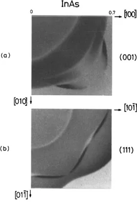
InAs
o
I)oo]
(Q) (001)
[01011
(b) (111)
FIG. 6. Reflection coefficient magnitude at a H20-InAs interface as a func- tion of direction cosines (horizontal and vertical axes 0 < sin 0 <0 7) plot- ted in two dimensions, (a) (100) plane, (b) (111) plane.
o o
o •
N
(a)
SAPPHIRE
0.3. [oo]
(100)
TABLE II. Minimum reflection angles for some hexagonal crystals at the H20 interface. Piezoelectricity neglected.
Hexagonal materials (001)plane, m=[001], n--[100] Material sin 0 Ti 0.2812 12.83 0.846 ZnO 0.5252 17.74 0.854 BeO 0.2005 14.28 0.908 CdS 0.8284 24.94 0.632
1
_.[001] (b) (OLO) (c) ,.[100]
I
[oo]
__. [oo] (001)FIG. 10. Reflection coefficient magnitude at a H20-sapphire interface as a function of direction cosines (horizontal and vertical axes 0 < sin 0 < 0.30) plotted in two dimensions, (a) (100) plane, (b) (010) plane, (c) (001) plane.
dimension, it is possible to use gray shadings as obtained on a grey scale graphics monitor. Figure 5 is such a presentation for the reflection coefficient amplitude at the interface between H20 with (001 ) and ( 111 ) planes of GaAs crystal.
Calculations are performed on a 128 by 128 grid. In the fig- ure the bright points correspond to a reflection coefficient that is close to unity whereas the dark points indicate a re- flection coefficient close to zero. The critical angles are clear- ly seen as boundaries of different regions. Figures 6-10 are
similar figures, which require extensive computation time,
for the H20-InAs, H20-silicon, H20-quartz, H20- LiNbO3, and H20-sapphire interfaces at different crystallo- graphic orientations of the solids. In all cases, the dark re- gions occur in a narrow path of direction cosines.
To find the position of the nulls--if they exist--we de- veloped a minimization program using the steepest descent technique. Since the reflection coefficient has a highly com- plicated structure, it is possible to miss the real minimum and instead find a local minimum. We tried to find the null i n the reflection coefficient magnitude for a number of materi- als. The constants of all the materials were taken from
Auld. 6 We summarize the results in Tables I-IV. They show
the positions of nulls or minima for various materials at some crystallographic orientations. For cubic materials the ani- sotropy factor •1 = 2c44/(Cll -- C12 ) is also listed. In the ta-
bles,
0 is the polar angle,
which
is between
the incidence
direction and the m direction, and • is the azimuth angle, which is between the incidence plane and the n direction, where m and n are as defined in the tables.
'To show
the angular
extent
of the nulls,
we plotted
the
reflection coefficient at and around the nulls. Figures 11 and 12 show the reflection coefficient magnitude and phase for two cubic materials at their ( 111 ) planes. Typically, as the anisotropy factor •1 increases, the angular extent of the null gets wider for (00 ! ) and ( 111 ) planes of cubic crystals. The
TABLE I. Minimum reflection angles for some cubic materials at the H20 interface. Piezoelectricity neglected.
(001 ) plane (011 ) plane
Cubic m = [001 ], n = [ 100] m = [011 ], n = [01•]
materials
.
Material •1 sin 0 ,/, I al sin 0 ,½ J RJ
( 111 ) plane m= [111],n= [101] sin 0 ½ I RI Cu 3.18 0.6655 25.16 0.037 0.6800 40.84 0.704 Ni 2.63 0.5123 25. 66 0.049 0.5317 40.72 0.765 Fe 2.41 0.4802 25.30 0.023 0.5020 40.57 0.739 InAs 2.08 0.6796 24.01 0.016 0.7111 42.45 0.402 GaAs 1.82 0.5301 24.93 0.001 0.5465 46.96 0.470 Si 1.56 0.2980 26.99 0.026 0.3019 44.88 0.179 A1 1.22 0.5030 32.37 0.090 0.4838 7.95 0.744 PbS 0.508 0.8100 0.00 0.710 0.7418 18.31 0.005 0.5495 30.00 0.051 0.4380 24.89 0.036 0.4170 22.96 0.056 0.6187 15:69 0.047 0.4742 20.37 0.014 0.2655 28.25 0.080 0.4700 29.99 0.290 0.7301 9.263 0.302
TABLE III. Minimum reflection angles for some tetragonal crystals at the H20 interface.
Tetragonal materials (001)plane, m=[001], n=[100]
Material /3 sin 0 4 IRI
TeO2 29.29 0.7433 28.65 0.009
TiO2 4.06 0.2982 33.42 0.053
converse is true for (011 ) planes. Figure 13 depicts the re- flection coefficient for a cubic material at its (011 ) plane.
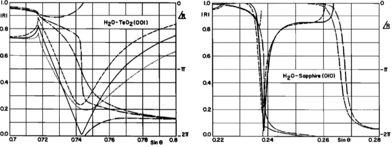
Figure 14 is a similar presentation for a tetragonal material at its X- Y (001 ) plane. Notice that TeO2 is an unusually high anisotropic material, and the extent of the null is remarkably wide. Figures 15 and 16 show the reflection coefficient null
for two common trigonal materials, quartz and sapphire. An
important observation in all cases is that there is a phase
transition of the reflection coefficient at the angle of mini-
mum amplitude. This transition is different from the phase
transition associated with the Rayleigh wave excitation that
occurs at greater angles and at which all waves in the solid
are evanescent. Both transitions are visible in Figs. 12 and
16. The phase transition at the amplitude minimum corre- sponds to a surface wave excitation as discussed in the next
section.
III. DISCUSSION
The presence of the reflection coefficient nulls was
shown to exist for (001 ) planes of some cubic crystals ear- lier. 8 We now see that such angles exist for other planes of solids and are not limited to (001) faces of cubic crystals.
The discussion given in Ref. 8 claimed that the null in the
reflection coefficient would occur at an angle corresponding
to an excitation of a pseudosurface wave. The pseudosurface
waves were first encountered in surface-acoustic-wave 14-15
and reflectivity experiments. 16-18 The most complete treat-
ment of the pseudosurface
wave
was given
by Lim 19
and
Farnell. 2ø In contrast to the Rayleigh waves, which are sur-face waves, the pseudosurface waves are actually bulk waves that are traveling very close to the surface and, hence, acting like a surface wave radiating the energy of the wave into the bulk. They were also the subject of some recent investiga-
tions
in conjunction
with phonon
imaging.
2l
The null angles in the reflection coefficient were first
TABLE IV. Minimum reflection angles for some trigonal crystals at the H:O interface. Piezoelectricity neglected.
Trigonal materials
Material sin 0 • IRI
Quartz (OOl), m = [OOl], n = [lO0] Quartz (lO0), m = [lO0], n = [010] Quartz (010), m = [010], n = [o01] Sapphire(001), m=[001], n=[100] Sapphire(100), m=[100], n=[010] Sapphire (010), m= [010], n= [001] LiNbO3 (010), m = [010], n = [001] 0.3863 11.81 0.295 0.3929 44.50 0.027 0.3728 42.53 0.370 0.2277 55.26 0.686 0.2340 42.49 0.619 0.2386 -- 0.50 0.066 0.3988 166.86 0.044 1.0 IRI .0.8 0.6 0.4 0.2 0.0
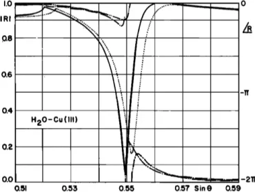
H20_Cu(111
)
!i
!
0.51 0.53 0.55 0.57 Sin 0 0.59FIG. 11. Reflection coefficient magnitude at a HeO-Cu ( 111 ) interface near the null as a function of incidence angle for azimuthal angles of 30 ø (solid), 27 ø (dotted), 33 ø (dotted) and phase for 30 ø (dash-dot), 27 ø
(dash-dot-dot), 33 ø (dash-dot-dot).
observed
experimentally
by Rollins.
•6 He noted
that, for
some orientations, the dip associated with the pseudosurface wave was much stronger than that related to the Rayleigh wave. The latter dip is strongly dependent on the absorption of Rayleigh waves and its physical interpretation is well un-
derstood. 2 The first dip is due to the fact that incident longi-
tudinal waves in the liquid medium is coupled almost com- pletely into the pseudosurface waves. He reported the observation of complete nulls for the Y-Z plane of quartz corresponding to the pseudosurface wave excitation.
Farnell 2ø indicated that the pseudosurface waves will
exist on the (001 ) and ( 111 ) planes of the cubic crystals as long as the condition (c• - c•2)/2 < c44 is satisfied. Similar-
IRI 0.8 0.6 0.4 02
FIG. 12. Reflection coefficient magnitude at a H:O-GaAs ( 111 ) interface near the null as a function of incidence angle for azimuthal angles of 17.37 ø (dotted), 20.37 ø (solid), 23.37 ø (dashed) and phase for 17.37 ø (dash-dot- dot), 20.37 ø (dash-dot), 23.37 ø (dash-long dash).
1.0 0 IRI 0.8 Q6 -11' 0.4 0.2 0.0 -211' 0.80 0.70 0.72 0.74 0.76 0.78 Sin 0
FIG. 13. Reflection coefficient magnitude at a H20-PbS (011 ) interface near the null as a function of incidence angle for azimuthal angles of 17.31' ( dotted ), 18.31' (solid), 19.31' (dashed) and phase for 17.31' (dash-dot- dot), 18.31 ø (dash-dot), 19.31' (dash-long dash).
ly, the (011 ) planes of cubic crystals will support the pseu- dosurface waves, if (c::- c:2)/2 •½44 is satisfied. Inspec- tion of Table I indicates that these conditions are indeed consistent with our findings. We find nulls in the (001 ) and ( 111 ) planes of those cubic materials that have r/) 1, and in the (011 ) planes for which r/< 1. If the cubic materials is nearly isotropic (like A1) there is a deep minimum, but it is not a complete null. Specifically, the (001 ) and ( 111 ) planes of crystalline copper support the pseudosurface waves and
they were experimentally
observed.
•7 The calculated
posi-
tion of nulls correspond to surface wave velocities of 2267 m/s for the (001 ) plane and 2746 m/s for the ( 111 ) plane.
1.0 IRI 0.8 0.6 0.4 0.2 0.0 -W
FIG. 15. Reflection coefficient magnitude at a H20-quartz (100) interface near the null as a function of incidence angle for azimuthal angles of 43.5 ø (dotted), 44.5 ø (solid), 45.5 ø (dashed) and phase for 43.5 ø (dash-dot-dot), 44.5* (dash-dot), 45.5 ø (dash-long dash).
These numbers and the azimuthal angles indeed agree very well with the measured and theoretically calculated veloc-
ities of the pseudosurface waves as shown in Figs. 1 and 2 of Ref. 17. The correspondence between the null angles and the pseudosurface waves can be more easily seen in Figs. 5-10. There the path followed by the dark regions maps the angu- lar position (sin 0 and •b) of the pseudosurface waves. Exis- tence of phase transitions at the amplitude minima as seen in Figs. 11-16 supports further the claimed association between the pseudosurface waves and the null angles.
During our search for nulls in various anisotropic mate-
rials, we were unable to find a null in the hexagonal materials under consideration. But, all the tetragonal materials we ex-
amined, exhibited a null. As indicated by Farnell 2ø the ratio /• = 2C66/(Cll I C12 ) plays a similar role with the tetragonal
I.O 0 H20-Te02(001)
0.8
• x I / / ... ...-xX'
0.6
• X•
?
.."
/ •
...
"
...
o.,
..,-
02
"'
...
.• • • _
0.0 0.7 0.7• 0.74 0.76 0.• $1n ß 0.8 1.0 IRI 0.8 0.6 -11' 0.2 0.0 -211' 0.22 0.24 0.26 Sin o 0.28FIG. 14. Reflection coefficient magnitude at a H20-TeO2 (001) interface near the null as a function of incidence angle for azimuthal angles of 25.65* (dotted), 28.65* (solid), 31.65' (dashed) and phase for 25.65* (dash-dot- dot), 28.65* (dash-dot), 31.65' (dash-long dash ).
FIG. 16. Reflection coefficient magnitude at a H20-sapphire (010) inter- face near the null as a function of incidence angle for azimuthal angles of 3.19' (solid), 9.0* (dashed), and phase for 3.19 ø (dash-dot), 9.0 ø (dash- long dash).
crystals as did V for the cubic crystals. Out of the three planes of the quartz crystal, only the Y-Z (100) plane gave a null in the reflection coefficient. This is consistent with previous
experimental results •4'•5 that showed that only the (100)
plane of quartz has a pseudosurface wave. Moreover, the reported phase velocity and the azimuthal angle agree with our findings. As Table IV indicates only the X-Z (010) planes of sapphire and LiNbO3 exhibit nulls. Note that, in all computations piezoelectricity is neglected. So, our results apply only approximately for piezoelectric materials. IV. CONCLUSION
In this article, the results of numerical calculations on the acoustical reflection problem at the liquid-anisotropic- solid interface are presented and reflection coefficient plots for various solids are obtained. The null found in the reflec- tion coefficient for some materials corresponds to an effi- cient excitation of a pseudosurface wave in the solid materi- al. Amo,ng the anisotropic materials we examined those sur- faces that support pseudosurface waves seem to have a null in the reflection coefficient. It is possible to some extent to classify the crystalline materials for the existence of the pseu- dosurface waves. In general, materials which are nearly iso- tropic do not support pseudosurface waves, and hence, they do not have nulls in the reflection coefficient. In particular, we have determined that the presence and angular extent of the null angle depend on the anisotropy factor in cubic mate- rials. For (001 ) and ( 111 ) planes a high anisotropy factor will correspond to a wide null in the reflection coefficient. On the contrary, the (011 ) plane of a cubic material requires an anisotropy factor smaller than unity for the presence of the null angle. We were unable to find nulls in a few materials we examined that belong to the hexagonal crystal class. All tetragonal materials under investigation showed nulls at their (001 ) planes.
The presence of the null angle provides a wideband matching from a bulk wave in the liquid to a shear wave in the solid. By reciprocity the same should hold true when a QS wave is incident on the solid-liquid interface from the solid side at the proper angle. This fact can be used as a method for coupling acoustic power from one side to the other without any bandwidth limitation. One disadvantage of this method is that this coupling occurs only for a very narrow angular aperture, hence, one has to use wide beams with a narrow angular spectrum.
ACKNOWLEDGMENT
Some of this work was done while the first two authors
were with the Electrical and Electronics Engineering De-
partment of Middle East Technical University in Ankara, Turkey.
•L. M. Brekhovskikh, Waves in Layered Media (Academic, New York,
1980).
'-G. Mott, "Reflection and refraction coefficients at a fluid-solid interface,"
J. Acoust. Soc. Am. 50, 819-829 (1971).
3W. G. Neubauer, "Ultrasonic reflection of a bounded beam at Rayleigh and critical angles for a plane liquid-solid interface," J. Appl. Phys. 44,
48-55 (1973).
4E. G. Henneke, II "Reflection-refraction of a stress wave at a plane bound- ary between anisotropic media," J. Acoust. Soc. Am. 51, 210-217 (1972). -•E. G. Henneke, II and G. L. Jones, "Critical angle for reflection at a liq-
uid-solid interface in single crystals," J. Acoust. Soc. Am. 59, 204-205
(1976).
6B. A. Auld, Acoustic Fields and Waves in Solids ( Wiley-Interscience, New
York, 1973), Vols. 1 and 2.
7G. L. Jones and E.G. Henneke, II, "Reflection of stress waves at a free boundary in quartz single crystals," IEEE Trans. Sonics Ultrason. SU-20,
267-274 (1973)
8A. Atalar, "Reflection of ultrasonic waves at a liquid-cubic-solid inter-
face," J. Acoust. Soc. Am. 73, 435-440 (1983).
9M. G. Somekh, G. A.D. Briggs, and C. Ilett, "The effect of elastic anisot- ropy on contrast in the scanning acoustic microscope," Philos. Mag. A 49,
179-204 (1984).
iøG. M. Crean and A. Waintal, "Average Rayleigh-wave velocity of a com- puter-simulated crystallographic plane," J. Appl. Cryst. 19, 181-187
(1986).
•V. R. Velasco and F. Garcia-Moliner, "Theory of surface waves in aniso- tropic cubic crystals," J. Phys. C: Solid State Phys. 13, 2237-2256 (1980). •2S. I. Rokhlin, T. K. Bolland, and L. Adler, "Reflection and refraction of
elastic waves on a plane interface between two generally anisotropic me-
dia," J. Acoust. Soc. Am. 79, 906-918 (1986).
•3S. I. Rokhlin, T. K. Bolland, and L. Adler, "Splitting of domain of angles for incident wave vectors in elastic anisotropic media," J. Appl. Phys. 59,
3672-3677 (1986).
14U. Engan, K. A. Ingebrigtsen, and A. Tonning, "Elastic surface waves in a-quartz: Observation of leaky surface waves," Appl. Phys. Lett. 10, 311-
313 (1967).
•SL. V. Verevkina, L. G. Merkulov, and D. A. Tursunov, "Surface waves in a quartz crystal," Sov. Phys. Acoust. 12, 254 (1967).
16F. R. Rollins, "Ultrasonic examination of liquid-solid boundaries using a right-angle reflector technique," J. Acoust. Soc. Am. 44, 431-434 (1968). •7F. R. Rollins, T. C. Lim, and G. W. Farnell, "Ultrasonic reflectivity and
surface wave phenomena on surfaces of copper single crystals," Appl. Phys. Lett. 12, 236-238 (1968).
•80. I. Diachok, R. J. Hailermeier, and W. G. Mayer, "Measurements of ultrasonic surface wave velocity and absorptivity on single-crystal cop- per," Appl. Phys. Lett. 17, 288-299 (1970).
19T. C. Lim and G. W. Farnell, "Character of pseudo surface waves on anisotropic crystals," J. Acoust. Soc. Am. 45, 845-851 (1969).
2øG. W. Farnell, "Properties of elastic surface waves," in PhysicalAcoustics, edited by W. P. Mason and R. N. Thurston (Academic, New York, 1970), Vol. 6, pp. 109-166.
2•A. G. Every, "Pseudosurface wave structures in phonon imaging," Phys.
Rev. B 33, 2719-2732 (1986).