MICROFLUIDIC SYNTHESIS OF
POLYHEDRAL OLIGOMERIC
SILSESQUIOXANE (POSS) BASED
ORGANIC-INORGANIC HYBRID
MICROPARTICLES
a thesis submitted to
the graduate school of engineering and science
of bilkent university
in partial fulfillment of the requirements for
the degree of
master of science
in
mechanical engineering
By
Umutcan C
¸ alı¸skan
September 2019
Microfluidic synthesis of polyhedral oligomeric silsesquioxane (POSS) based organic-inorganic hybrid microparticles
By Umutcan C¸ alı¸skan September 2019
We certify that we have read this thesis and that in our opinion it is fully adequate, in scope and in quality, as a thesis for the degree of Master of Science.
Barbaros C¸ etin(Advisor)
C¸ a˘glar Elb¨uken
Hatice Duran Durmu¸s
Approved for the Graduate School of Engineering and Science:
Ezhan Kara¸san
ABSTRACT
MICROFLUIDIC SYNTHESIS OF POLYHEDRAL
OLIGOMERIC SILSESQUIOXANE (POSS) BASED
ORGANIC-INORGANIC HYBRID MICROPARTICLES
Umutcan C¸ alı¸skan
M.S. in Mechanical Engineering Advisor: Barbaros C¸ etin
September 2019
Utilizing microfluidic systems inevitably changes tools used in chemistry due to advantages such as handling differential volume, controlled reaction environ-ment, enhanced mixing performance, less time required to complete reaction. Hence microfluidic reactors become more popular among microparticle synthesis tools. This research work presents synthesis of organosilica nano-cage structures, namely Polyhedral oligomeric silsesquioxane (POSS) particles, based on organic-inorganic hybrid microparticles by utilizing dispersion and emulsion polymer-ization methods. Firstly, poly(M-POSS) microparticles are synthesized via dis-persion polymerization method by using continuous flow microreactors, one of which is operated on a hot plate and the other one has temperature controlled dual zone with embedded electrodes. Synthesized microparticles in microreactors are characterized in terms of morphology, thermal behavior and surface chemical structure. Effects of different parameters such as monomer, initiator and sta-bilizer amount are presented. Secondly, in a temperature controlled continuous flow microfluidic reactor with embedded thin film electrode, epoxy functional-POSS microparticles have been synthesized via emulsion polymerization method. Heater for the microfluidic reactor is designed by COMSOL Multiphysics and manufactured in cleanroom to achieve homogeneous temperature distribution. Effects of flow rate, temperature and concentration of monomers are presented. In addition, same microfluidic reactor without electrodes immersed in oil bath and polymerization is observed and results are compared with the electrode in-tegrated reactor.
Keywords: microfluidics, organic-inorganic hybrid microparticles, microparticle synthesis, polyhedral oligomeric silsesquioxane (POSS).
¨
OZET
MıKRO AKIS
¸KAN SISTEM KULLANILARAK
POLYHEDRAL OLIGOMERIC SILSESQUIOXANE
(POSS) TABANLI ORGANIK-INORGANIK PARC
¸ ACIK
SENTEZI
Umutcan C¸ alı¸skan
Makine M¨uhendisli˘gi, Y¨uksek Lisans Tez Danı¸smanı: Barbaros C¸ etin
Eyl¨ul 2019
Mikroakı¸skan sistemlerin diferansiyel hacimde kullanımı, kontroll¨u reaksiyon ortamı, geli¸smi¸s karı¸sım performansı, daha az zamanda reaksiyon tamamlama gibi avantajları oldu˘gundan, bir¸cok alanda oldu˘gu gibi kimya alanında da kullanılan ara¸cları etkilemesi ka¸cınılmazdır. Bu do˘grultudaki geli¸smeler, mikroakı¸skan reakt¨orleri mikropartik¨ul sentez ara¸cları arasında daha pop¨uler hale getirmi¸stir. Bu ara¸stırma ¸calı¸sması, dispersiyon ve em¨ulsiyon polimerizasyon y¨ontemleri kullanılarak organik ve inorganik hibrit mikropartik¨ullere dayanan, organosi-lika nano kafes yapılarının yani ¸cok y¨uzl¨u oligomerik silseskioksan (POSS) par-tik¨ullerinin sentezini sunmaktadır. ˙Ilk olarak, POSS mikropartik¨ulleri, ısıtıcı ¨
uzerinde s¨urekli akı¸s mikroreakt¨or¨u ve ¸cift b¨olgeli sıcaklık kontroll¨u, g¨om¨ul¨u ince film elektrota sahip s¨urekli akı¸s mikroreakt¨or¨u kullanılarak dispersiyon polimerizasyonu y¨ontemi ile sentezlenmi¸stir. Mikro reakt¨orlerde sentezlenen mikropartik¨uller morfoloji, termal davranı¸s ve y¨uzey kimyasal yapısı a¸cısından incelenmi¸stir. Akı¸s hızı, ba¸slatıcı miktarı ve dengeleyici miktarı gibi farklı parametrelerin etkileri g¨om¨ul¨u elektrotlu mikroakı¸skan reakt¨or¨unde ¸calı¸sılmı¸stır. Ek olarak, geleneksel sentez teknikleri ile konvansiyonel reakt¨orler kullanılarak polimerizasyon ger¸cekle¸stirilmeye ¸calı¸sılmı¸s ancak mikropartik¨ul olu¸sumu yer-ine, nano k¨umeler elde edilmi¸stir. ˙Ikinci olarak, g¨om¨ul¨u ince film elektrotlu mikroakı¸skan reakt¨or¨unde, epoksi fonksiyonel-POSS mikropartik¨ulleri em¨ulsiyon polimerizasyonu y¨ontemi ile sentezlenmi¸stir. Mikroakı¸skan reakt¨or¨undeki ısıtıcı Comsol Multiphysics’te tasarlanmı¸s ve homojen sıcaklık da˘gılımının sa˘glandı˘gı g¨or¨ulm¨u¸st¨ur. Akı¸s hızı, sıcaklık ve monomerlerin konsantrasyonunun etkileri sunulmu¸stur. Ayrıca, ya˘g banyosuna batırılmı¸s elektrotlar bulunmayan aynı mikroakı¸skan reakt¨or¨u kullanılarak polimerizasyon ger¸cekle¸stirilmi¸s ve elde edilen
v
par¸cacıkların karakterizyonlarının sonu¸cları raporlanmı¸stır.
Anahtar s¨ozc¨ukler : Mikro akı¸skanlar, organik-inorganik mikropar¸cacı sentezi, Polyhedral Oligomeric Silsesquioxane (POSS).
Acknowledgement
I would like to express my sincere thanks to my advisor, Dr. Barbaros C¸ etin who guided me with valuable help and contributions throughout my whole grad-uate studies. I would like to appreciate Dr. G¨une¸s Kibar who gave me a lot of knowledge in both engineering and science. She has generous contribution in my chemistry background and particle characterization. I am deeply thankful for the valuable advice, having an insightful attitude, warm encouragement and endless support provided to me. It was a great pleasure to work with her. I would like to thank the faculty members of the Department of Mechanical Engineering at Bilkent University. In addition, I would like to express my gratitude to Mr. Semih Bozkurt and Mr. Abdullah Kafadenk from UNAM for helping me with device usage and manufacturing procedures.
I would like to express my special thanks to Ms. Hatice Dilara Uslu, my friend from freshman year, contributing me with all of her facilities, providing motivation and among all, her invaluable friendship. Moreover, I have special thanks to Mr. Cem Kurt, Mr. ˙Ibrahim Nasuh Yıldıran, Ms. ˙Ipek Karsu Kılı¸c and Mr. Okan Deniz Yılmaz for their valuable friendship.
I owe my deepest gratitude to the most precious person in my life, Ms. S¸ule Berna Ayan for being with me all the time with her eternal assistance. I owe my family (Fatma and Mehmet Akif) a debt of gratitude for their unflagging support and sacrifices made for me.
I would also thank the Turkish Scientific and Technical Research Council (TUB˙ITAK)–M¨unir Birsel Lisans Ust¨u BurslarıVakfıfor the financial support dur-ing my master period.
Contents
1 Introduction 1
1.1 Dispersion Polymerization Method . . . 7
1.2 Emulsion Polymerization Method . . . 10
1.3 Materials . . . 13
1.4 Objectives and Motivation . . . 15
1.5 Outline of the thesis . . . 16
2 Synthesis of Poly(M-POSS) Microparticle 18 2.1 Materials and Methods . . . 19
2.1.1 Materials . . . 19
2.1.2 Characterization . . . 20
2.1.3 Reactor Types . . . 20
2.2 Design and Fabrication of Microfluidic Reactor . . . 21
CONTENTS viii
2.4 Synthesis in Batch Reactor . . . 26
2.5 Synthesis in Microfluidic Reactors . . . 27
3 Synthesis of Poly(M-POSS-co-GMA) Microparticles 37 3.1 Materials and Methods . . . 38
3.1.1 Materials . . . 38
3.1.2 Reactor Types . . . 39
3.2 Design of Embedded Electrode Microfluidic Reactor . . . 39
3.3 Fabrication of Microfluidic Reactors . . . 41
3.4 Experimentation . . . 46
4 Summary and Future Research Directions 55
A Simple Chemical Cleaning 66
List of Figures
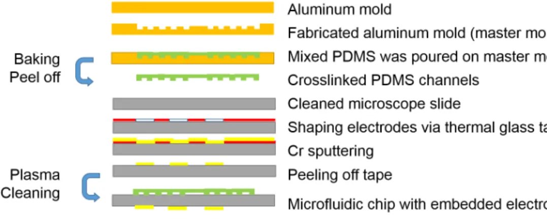
2.1 Demonstration of fabrication steps of microfluidic chip with em-bedded electrode . . . 22 2.2 A) Fabricated aluminum mold, B) Microfluidic reactor for hot plate
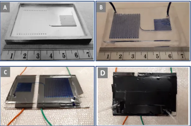
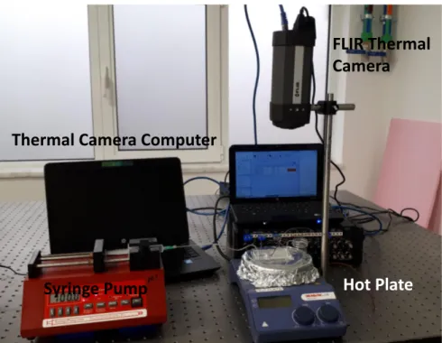
configuration, C) Fabricated microfluidic reactor with embedded electrode D) Microfuidic reactor covered with tape to increase ther-mal camera’s reading performance . . . 23 2.3 Experimental setup of microfluidic reactor on hot plate . . . 24 2.4 Experimental setup of microfluidic reactor with integrated thin
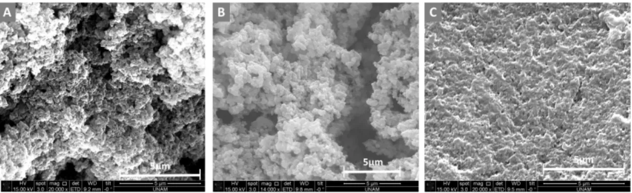
film electrode . . . 25 2.5 SEM image and morphological character of poly(M-POSS)
ob-tained by dispersion polymerization with different momoner amounts: (A) 0.06 g POSS, (B) 0.12 g POSS, and (C) 0.24 g POSS in conventional batch reactor. (Reaction conditions: magnetically stirred at 70◦C for 6 h) . . . 27 2.6 Thermal camera images of (A) electrode embedded microfluidic
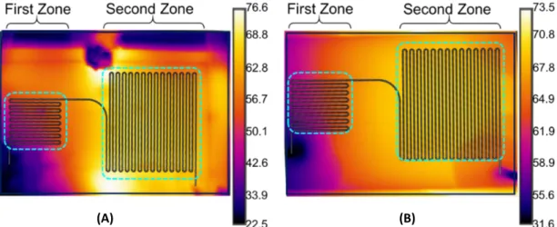
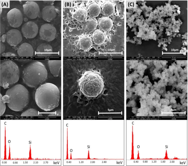
reactor and (B) microfluidic reactor placed on hot plate . . . 28 2.7 SEM images and EDX spectra of poly(M-POSS) synthesized in (A)
microfluidic reactor placed on hot plate, (B) electrode embedded microfluidic reactor, and (C) conventional reactor . . . 29
LIST OF FIGURES x
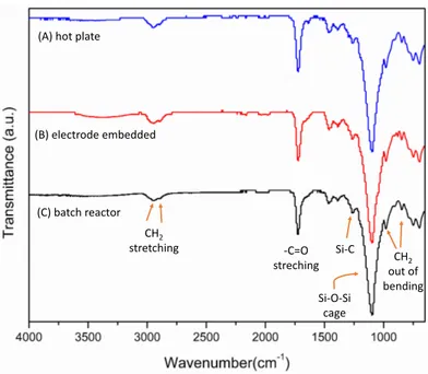
2.8 Surface chemical structural characterisitcs of synthesized poly(M-POSS) in (A) microfludic reactor placed on hotplate, (B) electrode embedded microfluidic reactor, and (C) batch reactor. . . 31 2.9 TGA and DTG curves weight % loss of poly(M-POSS) structures
synthesized in (A) batch reactor, (B) microfludic reactor placed on hotplate, and (C) electrode embedded microfluidic reactor. . . 32 2.10 The morphological character of poly(M-POSS) microparticles
while sweeping the initiator ratio(AIBN amount with respect to POSS amount by weight)(A) 25% (w/w), (B) 50% (w/w), (C) ap-proximately equal amount to monomer. The microfluidic reactor placed on the hot plate (flow rate of 15µl/min) is represented as -15H and the microfluidic reactor with embedded electrode (flow rate of 90µl/min) is represented as -90E . . . 33 2.11 The morphological character of poly(POSS) polymerization within
the microfluidic reactor with embedded electrodes by changing the stabilizer ratio to dispersion (PVP K-30 amount with respect to dispersion medium by weight /volume): (A) 0.04% (w/v), (B) 0.075% (w/v), (C) 0.14% (w/v) while the other parameters held constant The microfluidic reactor placed on the hot plate (flow rate of 15µl/min) is represented as -15H and the microfluidic reactor with embedded electrode (flow rate of 90µl/min) is represented as -90E . . . 34 2.12 The morphological character of poly(M-POSS) microparticles
while sweeping monomer ratio to dispersion (POSS amount with respect to dispersion medium by weight /volume):(A) 0.4% (w/v); (B) 0.8% (w/v), (C) 1.6% (w/v) while the other parameters held constant. The microfluidic reactor placed on the hot plate (flow rate of 15µl/min) is represented as -15H and the microfluidic reac-tor with embedded electrode (flow rate of 90µl/min) is represented as -90E . . . 35
LIST OF FIGURES xi
3.1 Depiction of microfluidic reactor . . . 40 3.2 Temperature distribution in microfluidic reactor . . . 41 3.3 Demonstration of fabrication steps of microfluidic reactor with
em-bedded electrode . . . 42 3.4 Fabrication steps of microfluidic reactor with embedded electrode:
A) fabricated brass mold, B) Crosslinked PDMS channels, C) after growing SiO2 on the back side, thin film heater is deposited on
surface, D) electrical connections on the heater, E) Si wafer bonded with PDMS channels, F) final version of chip . . . 43 3.5 Experimental set up of microfluidic reactor in oil bath . . . 47 3.6 Synthesis schematic of POSS GMA in immersed microfluidic reactor 48 3.7 The morphological character of poly(POSS) particles obtained by
90 µl/min flow rate in different magnification bar A)5000X, B) 10000X, C) 20000X . . . 49 3.8 The morphological character and size distribution of poly(POSS)
particles obtained by 40 µl/min flow rate in different magnification A)30,000X, B) 50,000X, C) 100,000X . . . 49 3.9 The morphological character and size distribution of poly(POSS)
particles obtained by 20 µl/min flow rate in different magnification A)20,000X, B) 30,000X . . . 50 3.10 Experimental set up of heater integrated microfluidic reactor . . . 51 3.11 The morphological character of poly(M-POSS-co-GMA)
parti-cles obtained by 5ul/min flow rate in different magnification bar A)20000X, B) 100000X, C) 200000X . . . 52
LIST OF FIGURES xii
3.12 The morphological character of poly(POSS-co-GMA) particles containing 5% GMA as co-monomer in weight obtained by 50ul/min flow rate in different magnification bar A)20000X, B) 30000X, C) 50000X . . . 52 3.13 The morphological character of poly(POSS-co-GMA) particles
containing 5% GMA as co-monomer in weight obtained by 100ul/min flow rate in different magnification bar A)20000X, B) 30000X, C) 50000X . . . 52 3.14 FTIR comparison of POSS monomer, GMA co-monomer,
poly(M-POSS) and poly(M-POSS-co-GMA) . . . 53 3.15 FTIR comparison of poly(M-POSS) and poly(M-POSS-co-GMA) 54
List of Tables
1.1 Hybrid Particles in Literature . . . 6
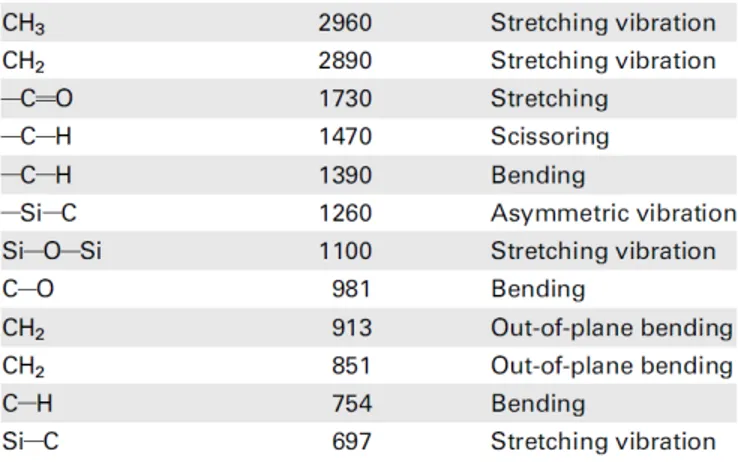
2.1 FTIR peaks of synthesized Poly(M-POSS) structures . . . 30
Chapter 1
Introduction
Fast developments in microfabrication techniques urge to use of microfluidic in which very small amount of sample fluid in the order of 10−9 to 10−18 liters is handled via 10µm to 1000µm channels in different areas such as point of care devices, lab-on-a-chip systems, chemistry as a synthesis and/or analysis of par-ticles. The main motivations of microfluidics are based on molecular analysis, biodefence, molecular biology and microelectronics. In chemistry, improvements in microanalytical methods based on capillary have changed perspective of de-velopers towards more compact methods than conventional methods. Moreover, microanalysis advancements have triggered the understanding of genomics, so mi-croanalytical related molecular biology become hot topic in genomics. In addition, advances in bio-weapons forced governments think of early detection systems and detection in field via detectors for chemical and biological threats. To continue in this vein, high-throughput DNA sequencing, which requires high throughput, more sensitivity and more resolution compare to conventional methods, have been attracting attention, since genomics of the bio-weapons should be sequenced. Last but most important point is improvements in microelectronics. Developments in microfabrication techniques such as lithography techniques, silicon based fabrica-tion techniques promote use of more compact systems. All these advancements and necessity to use more compact systems have been enforcing developments in microfluidics [1]. In the light of these developments, micro total analysis systems
(µTAS) or lab on a chip was proposed by Manz et al. [2] as a concept of miniatur-ized total chemical analysis systems (TAS) in which chemical analysis could be done by microfluidic components with the help of advantages in phenomenon of microfluidics [3]. Hence, microfluidic platforms had been using in many different areas such as handling chemicals,manipulation and processing chemical reactions, detection, sequencing, analysis, separation, synthesis of particles [1, 3, 4].
As discussed by Elviraet al. [5],Haeberleet al. [3], Whitesides [1] and Wanget al. [6], microfluidic systems offers many advantages and advantages in chemistry is specifically discussed below.
• require less amount of reagent to operate. Low amount of sample provides more trial and less risk of hazard while working with chemicals. The effect of chance in parameters in reactions can be studied since sample is used lesser. In other words, it is easier to get information about reaction in microfluidics compare to conventional systems. Moreover, in synthesis, in which hazardous chemicals are used, it is safer to operate with less amount of reagent.
• fast reaction. Although, studies show that compare to conventional sys-tems space-time yields is higher in microfluidics syssys-tems, it is faster to get results in microfluidic systems. Hence, fast reaction should be considered as getting result in microfluidic is faster. Since the amount of reagents and volume of reactors are less, reactions are completed faster. Products can be analyzed and if needed, trials can be performed multiple times in less amount of time. In conventional systems, getting optimized results takes more time.
• safer reaction. In hazardous operations, it is better to use less reagent. Explosion risks toxicity risks are reduced.
• less thermal mass. Volume of used reagents and operated systems are smaller compare to conventional batch systems. Less amount of heat is required to operate.
• rapid heat transfer. Especially in lab on a chip systems, since surface area to volume ratio in channels are high, heat transfer occurs rapidly. • enhanced portability and smaller footprints. Chips used in
microflu-idic systems have less weight and smaller volume. Some examples such as insulin pumps or pregnancy tests can be carried in a pocket.
In microfluidic systems, glass, silicon and polymer based materials have been used. In the beginning, glass based materials were used in systems, because fabrication techniques of glass were well-known and conventional systems used glass based instruments. It is not easy to fabricate glass and since glass is not a good conductor compared to silicon, glass is not appropriate for microelectronic operations. Moreover, its thermal properties such as thermal conductivity is low compare to silicon. Hence, silicon started to used in microfluidic systems. Silicon is biocompatible, it is easier to fabricate and it offers enhanced thermal and electrical properties compared to glass. However, it is costly to fabricate silicon and glass. Furthermore, reactions can not be observed in silicon/glass based systems, because they are opaque. After the silicon/glass based systems, polymer, specifically polydimethylsiloxane (PDMS),based microfluidic systems became popular. They offer biocompatible, transparent, easier to fabricate and cheaper systems. Nowadays, silicon and polymers are preferred together based on the type of applications [1,3–6]. In chemistry, benefits of employing polymer based chips are easier observation of reaction (due to transparency), fast and cheaper fabrication and good thermal properties. On the other hand, polymer based chips are permeable which may not be preferred during reactions, absorb reagent in long period, but silicon based chips are not permeable and are chemically resistant. Hence, combined systems have been used in chemistry.
On the other hand, there are challenges needed to be solved in microfluidics. In chemistry applications, long operational time causes clogging in channels [1, 4–6]. Porosity and chemical properties of material of chip, flow rate, reaction kinetics are important parameters in clogging, but it is reported that scale up the systems is not suitable for microfluidics systems [4]. Rather than scale up, numbering up, which means paralleled usage of multiple systems at the same time, is more
applicable. Moreover, the risk of contamination of channel walls are higher. Organic-inorganic hybrid micro/nanoparticles are one of the most popular ma-terials studied in the last decade because of their multifunctional properties. Due to their organic component, they are bio-compatible and have respecified wet-ting characteristics (hydrophobic/hydrophilic). In addition, their inorganic part gives them unique mechanical, electrical, and magnetic properties which conse-quently, makes them suitable for many different applications such as drug de-livery, imaging, fuel cells, photo catalysts, cosmetics, packaging [7–12]. Among these hybrid particles, interest in polyhedral oligomeric silsesquioxanes (POSS) with cage structures has increased dramatically in the last few years. Unlike other hybrid materials, POSS has an inorganic core coated with organic substitutes. Having organic structures at the exterior of the material makes them compat-ible with other polymers which broaden their application areas [8]. The cage structure of polyhedral POSS—or poly(POSS)— and its derivatives have already been used for various applications. For instance, biocompatibility, thermal resis-tance, hardness, and composite structure of poly(POSS) was utilized for dental applications [13, 14] as well as an additive to enhance the thermal properties of materials [15]. Owing to mechanical and electrochemical properties, poly(POSS) was used as energy storage materials, proton exchange membranes, and super-capacitors [16]. Furthermore, cage structure and its functional groups allowed them to be used as a metal-free catalysis for the polymerization of polycaprolac-tone [17]. The modification of poly(POSS) with the addition of functional groups is also possible and through this, a variety of ionic properties can be obtained for applications in chromatographic separation in monolithic columns [18]. The synthesis of functional poly(POSS) can be performed by using photo initiation, thermal initiation, or click chemistry [18].
In the last few years, there have been several microfluidic reactors that are used for the synthesis of hybrid nanoparticles [19–21] and microparticles [22–28]. Among these, Hong et al. synthesized liposome-hyrdogel hybrid nanoparticles by utilizing hydrodynamic flow focusing; Zhang et al. [19], Liu et al. [20] and Feng et al. [21] demonstrated the synthesis of core-shell nanoparticles composed of polymer core and lipid shell in multiphase liquid continuous flow reactors for
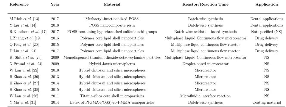
mainly drug delivery purposes [19–21]; Shiba et al. [23] presented the synthe-sis of nanoporous, monodispersed titanium dioxide-octadecylamine particles in a multiphase liquid continuous-flow microreactor. Prasad et al. [24] synthesized hybrid Janus microspheres in a droplet-based device with 3.5% of size variation. Lanet al. [22] and Zhaoet al. [26–28] employed microreactors to synthesize hy-brid microspheres composed of chitosan and silica. Lan et al. [25] performed an interface reaction to synthesize titania-silica core-shell microparticles in a droplet-based device. Table 1.1 summarizes the literature on hybrid particle synthesis for both batch methods and microfluidic approaches. All of these chemical synthesis techniques took place in conventional batch reactors, and until now poly(POSS) microparticles without any additional copolymer is not obtained successfully by a dispersion polymerization method in these systems. POSS synthesis was achieved using double zone temperature controlled microfluidic reactor and published by the author [29]. In addition to dispersion polymerization, emulsion polymer-ization method was used to synthesize POSS composite latexes which improve surface wettability and thermal stability of the composite surface [30]. Moreover, latex of P(GMA-POSS)-co-PMMA as a coating material is synthesized by em-ploying emulsion polymerization and advancing in hydrophobicity, thermal and mechanical properties is achieved [31].
Table 1.1: Hybrid Particles in Literature
Reference Year Material Reactor/Reaction Time Application
M.Rizk et al. [13] 2017 Methacryl-functionalized POSS Batch-wise synthesis Dental applications
Y.Liu et al. [14] 2018 POSS nanocomposite resin Batch-wise synthesis Dental applications
R.Kunthom et al. [17] 2017 POSS-containing hyperbranched sulfonic acid groups Batch-wise oxidation based synthesis Not specified (NS)
L.Zhang et al. [19] 2015 Polymer core lipid shell nanoparticles Multiphase Liquid Continuous flow microreactor Drug delivery
Q.Feng et al. [20] 2015 Polymer core lipid shell nanoparticles Multiphase liqud continuous flow reactor Drug delivery
D.Liu et al. [21] 2017 Polymer core lipid shell nanoparticles Multiphase liqud continuous flow reactor Drug delivery
K. Shiba et al. [23] 2009 Monodispersed titanium dioxide-octadecylamine particles Multiphase Liquid Continuous flow microreactor NS
N.Prasad et al. [24] 2009 Hybrid Janus microspheres Droplet-based microreactor NS
W.Lan et al. [22] 2010 Hybrid chitosan and silica microspheres Microreactor NS
H.Zhao et al. [26] 2013 Hybrid chitosan and silica microspheres Microreactor NS
H.Zhao et al. [27] 2014 Hybrid chitosan and silica microspheres Microreactor NS
H.Zhao et al. [28] 2015 Hybrid chitosan and silica microspheres Microreactor NS
W.Lan et al. [28] 2011 Titania-silica core shell microparticles Microfluidic interface reaction NS
Y.Ma et al. [31] 2014 Latex of P(GMA-POSS)-co-PMMA nanoparticles Batch-wise synthesis Coating material
1.1
Dispersion Polymerization Method
Dispersion polymerization is used to produce micrometer (1-10µm) sized monodisperse polymeric particles. It arouses great interest with its high effi-ciency in preparing polymer particles with homogeneous size distribution and taking place in one stage [32, 33]. This method can be defined as a particular type of precipitation polymerization in which a monomer is polymerized within a reaction medium in the presence of a suitable stabilizer. The solvent is a good solvent for the polymerization monomer, stabilizer and initiator, but not for the polymer formed. The resulting polymer particles are stable in the reac-tion medium [34, 35]. Dispersion polymerizareac-tion can be divided into two main stages. The first stage in which particles and nuclei are formed and aggrega-tion prevails between them is the stage of particle formaaggrega-tion. The next stage in which particle growth is predominant is particle growth stage [36]. In dispersion polymerization, all components are dissolved at the beginning of the reaction. When this homogeneous reaction mixture is heated, free radicals are formed by disruption of the initiator and continuous phase growth begins with monomer addition. Free radicals that reach a sufficiently high chain length subside and the stabilizer adsorbs to the surface of the formed particles to stabilize the particles. As soon as the particles are formed, monomer adsorption begins from the contin-uous phase. After formation of a sufficient number of particles which is capable of capturing free radicals in the continuous phase, the free radicals cannot grow to a high degree of polymerization. The polymerization essentially continues in the formation of monomer-swollen particles until all monomers are depleted [37]. Paine [38] determined that the in situ stabilizer formed by the chain transfer reaction of the radical and the stabilizer molecule plays an important role in the particle formation stage. According to Paine, the stabilized particles whose sur-face is coated with an in situ stabilizer do not cluster with each other. When the particles which capture the radicals in the continuous phase are sufficiently stabilized, no new nuclei or particles are formed. After particle formation, there are two manner where the polymerization will proceed; these are polymer parti-cles and continuous phase. Most of the monomers and initiator are in continuous phase. Almost all initiation and growth reactions of oligomeric radicals occur in
continuous phase. When the number of stabilized particles holding the oligomer radicals in the continuous phase is sufficient, the growth and termination reactions of the polymer radicals occur within the particle [39].
The effect of various parameters on the production of monodisperse parti-cles was investigated in many studies on dispersion polymerization. Molecular weight, size and size distribution of the particles synthesized by dispersion poly-merization and monomer conversion depend many factors, namely, initiator type and concentration, stabilizer type and concentration, mixing speed and shape, polymerization temperature, composition and type of the dispensing medium, monomer/dispersion medium volumetric ratio [40, 41]. Numerous experiments have been conducted in the literature for various parameters related to disper-sion polymerization. When polymerization experiments carried out at different temperatures in the range of 55-80◦C with increasing polymerization temperature, it was observed that average particle size and size distribution was increased but the molecular weight of the polymer was reduced [42]. The type and composi-tion of the dispersion medium is another factor affecting the average size and size distribution in dispersion polymerization. In dispersion polymerization, the desired dispersing media are those with high monomer solubility but low polymer solubility [40]. Systems with high monomer solubility and low polymer solubil-ity are considered to be ideal [40]. To a certain level, the volumetric ratio of monomer/dispersion medium is directly proportional to the particle size formed. If this ratio increases too much, the size distribution also increases. In the ex-periments, it was observed that the size of polymeric particles decreased with increasing concentration of stabilizer [40]. In addition, it was observed that the raise in the amount of initiator dissolved in the monomer phase leads to a raise in the size distribution of the particles formed and a raise in the reaction rate [43,44]. In the literature, water soluble polyacrylamide was prepared by dispersion polymerization. Researchers investigated the dispersion polymerization of acry-lamide using poly (vinyl methyl ether) stabilizer with using 2,2 azobisisobutyroni-trile (AIBN) [32, 45] and ammonium persulfate as initiators. Ye et al. [33] using AIBN and PVP in water/tert-butanol (TBA) synthesized polyacrylamide parti-cles of 300-1000 nm size by dispersion polymerization. By this method, Cho et
al. [46] prepared polyacrylamide in ammonium sulfate using poly (acryloxyethyl trimethyl ammonium chloride) (PAOTAC) as stabilizer with using 2,2-azobiz (2-methylpropionamidine) dihydrochloride (AIBA) as the initiator.
Organic–inorganic hybrid microparticles are popular materials studied in the last decade because of their versatile properties. They are accepted biocompatible due to their organic component and have specified hydrophobic/hydrophilic char-acteristics. Besides that, the inorganic section facilitates them specific magnetic, mechanical and electrical features. Hereby, they have several application fields such as packaging, pharmacological distribution, photocatalysts, imaging and cosmetics. Within these hybrid particles, the attention on polyhedral oligomeric silsesquioxanes (POSS) raised significantly in the last few years. Recently, Kibaret al. [29] procured spherical monodisperse POSS microparticles. They carried out a simple one-pot synthesis procedure to acquire organic–inorganic hybrid mi-croparticles in microfluidic reactors via dispersion polymerization. Furthermore, the synthesis of poly(POSS) in particle form inside a microfluidic system by dis-persion polymerization was introduced first [29].
Nanoclusters were represented the group of nanoparticles, which is defined as particle in range of 1 nm to 100 nm in size, at least one dimension and size distribution in narrow range. When they gathered, the different types of bonding forces could be acting like ionic, metallic, covalent, wan-der walls or hydrogen bonds. The widely used and the best technique to determine the nanoclusters is transmission electron microscope (TEM) characterization [47].
A hydrogel is defined as connected hydrophilic polymer chains and chains create a network. In water as a dispersion medium, they can be observed as a colloidal gel. A three-dimensional solid results from the hydrophilic polymer chains being held together by cross-links. Because of the crosslinking hydrogel does not dissolved in water medium [48].
1.2
Emulsion Polymerization Method
Emulsion polymerization is a method of polymerizing a water-insoluble monomer by emulsifying in water with the aid of suitable emulsifiers. In emulsion poly-merization, the medium contains water, monomer, micelle, and initiators [49]. Emulsion polymerization involves two immiscible phases. The dissolved monomer phase containing the initiator is dispersed in the water phase in emulsion form. The monomer phase is held in emulsion form in the dispersion phase with the aid of various emulsifiers. By emulsion polymerization, conjugated dienes such as butadiene and isopropene, vinyl acetate, vinyl chloride, various acrylates, poly-merization of methacrylates and different copolymers of these monomers can be produced [50]. Emulsion polymerization is a unique example of chain radical poly-merization. There are differences in reaction mechanism and characteristics such as dependence of molecular weight on polymer parameters and type of initiator used [51].
The emulsion polymerization can be divided into three groups according to the components present in the medium, such as conventional emulsion polymer-ization, reverse emulsion polymerization and emulsifier-free emulsion polymeriza-tion. In conventional emulsion polymerization, the emulsifier is dispersed with the monomer in a polar phase at the beginning of the reaction. As a difference in reverse emulsion polymerization, when the polarity of the monomer is very high, the polarity of the medium in which it is dispersed is much lower. In emulsion-free emulsion polymerization, no emulsifying agent is added into the medium at the beginning of the reaction and emulsifiers are formed during the reaction [52]. Standard emulsion polymerization is polymerization of a monomer or mixture of monomers by free radical polymerization in an emulsifier aqueous solution. Water, monomer, emulsifier, initiator and chain transfer agents, buffer and some-times a core latex are used to carry out this polymerization [53]. Buffers affect various impurities in emulsion polymerization, such as pH, hydroquinone between water and particulate phase. As a result, it affects the polymerization rate, molec-ular weight and particle size [54].
The emulsifier adsorbed on the surface of the monomer has a stabilizing effect and thus prevents the deterioration of the emulsion. When the polymerization starts, the monomers dispersed in the system proceed to the micelles and the monomer separates from the droplets and passes to the aqueous phase in order to maintain the monomer concentration in the aqueous phase. Micelles contain-ing polymer and monomer adsorb emulsifier molecules in solution while grow-ing. The monomer molecules which proceed to the aqueous phase by diffusion from the monomer droplets continuously feed the polymer particles and this pro-cess ensures that the monomer concentration remains constant. Over time, the monomer molecules decrease as the polymer particles grow, and the monomer molecules are depleted as the polymerization proceeds by 50-80%. Namely, all monomer molecules are interposed between the polymer particles. The polymer-ization ends with the termination of the chain reactions in the polymerpolymer-ization particles. In emulsion polymerization, 3 types of processes are applied: batch process, semi-batch process and continuous process. In the batch process, all substances are added to the reactor where the polymerization takes place. In the semi-batch process, the pre-emulsified monomers are added continuously or incrementally to the reactor where polymerization takes place. In the continuous process, all substances are completely added to a part of the reaction system and taken from another part of the latex reaction system partially or completely transformed [54].
Initiators: In emulsion polymerization, the initiators are selected according to their solubility in the monomer or solvent and the redox combination under the polymerization conditions. For these reasons, the type and concentration of the initiator affect the degree of polymerization [53]. As the concentration of the initiator increases, the degree of polymerization generally increases and the molecular weight decreases. Generally, 0.1-1% of monomer is used as ini-tiator in polymerization processes. Water-soluble iniini-tiators such as potassium or ammonium persulfate, hydrogen peroxide and 2.2-azobis (2-amido-propane) dihy-drochloride are used as initiators in emulsion polymerization. Iron ion persulfates are generally used in redox systems. In emulsion polymerization, water-soluble peroxides and persulfates are often preferred [54].
Emulsifiers: They are a class of chemical compounds known as amphiphiles and consist of two distinct regions, the first being polar (a dipole or charged group) and the other apolar (usually a hydrocarbon or halocarbon chain). Therefore, the molecules have limited solubility in any solvent and reduce the surface ten-sion between the two phases. The best-known examples are generally the most used soaps, such as sodium or potassium salts of organic fatty acids such as oleic, palmitic or stearic acid. Besides, sodium dodecyl sulfate (SDS) is the most commonly used emulsifier in emulsion polymerization [52].
In emulsion polymerization, the choice of emulsifier is very important as it affects the polymerization rate. The emulsifier ensures a stable emulsion between the water and the monomer phase. The increased amount of dissolved monomer in the aqueous phase reduces the surface tension of the water/monomer phase [55]. Emulsifier usage facilitates that an organic compound which is insoluble in water can move into the micelle and dissolve in the emulsifier solution. The polymer beads formed during the reaction are coated with the emulsifier and remain with-out coagulation during and after the polymerization. Thus, the polymer particles are protected against collapse by using emulsifier [56].
Advantageously from other processes, the polymer molecular weight is directly proportional to the rate of polymerization in emulsion polymerization. Further-more, the reaction temperature in emulsion polymerization is very low. Therefore, temperature control can be made easily. Since the viscosity of the medium is low, mixing and consequently heat transfer are easier. Therefore, the product transfer can be performed easily. Since water is generally used as a distribution medium, it is a low-cost and healthier method. In many applications, the product is syn-thetic latex and used directly. Examples include paint, surface coating, adhesives, latex foam, rubber. The disadvantage of emulsion polymerization compared to other processes is that more additives are used and additional processes such as separation, purification and drying are required to obtain the product from the emulsion medium if solid product is desired [51].
Dispersion polymerization has attracted great attention with high efficiency in preparing polymer particles with homogeneous size distribution and taking place
in one stage. Unlike emulsion polymerization, all components are dissolved at the beginning of the reaction in dispersion polymerization. In addition, the monomer phase dissolves in the dispersing phase, but the polymer formed at the end of the polymerization process does not dissolve in the dispersing phase [51]. According to research, it is stated that the stabilizer used in dispersion polymerization sta-bilizes the particles with the role of emulsifier as in emulsion polymerization. On the other hand, it is also noted that the stabilizer polymer molecules are inoc-ulated into the resulting polymer and the formed co-stabilizer performs particle stabilization. However, it has been determined that both mechanisms play a role in stabilization [37].
Polymer nanoparticles (PNPs) have an important role in a wide spectrum of areas ranging from electronics, biotechnology, sensors, conducting materials, medicine and environmental technology [57]. Using emulsion polymerization method, several studies were conducted to produce polymer nanoparticales such as poly(methylmethacrylate) (PMMA), poly(ethylcyanoacrylate) (PECA), and poly(butylcyanoacrylate) by dispersion via surfactants into solvents as the organic phase [57]. In addition to these particles, emulsion polymerization is used for synthesis of Polyhedral Oligomeric Silsesquioxane (POSS)-based polymers which have advantages of inorganic ingredient (rigidity and thermal stability) with or-ganic polymers (flexibility and ductility) [31]. For instance, Liaoet al. [30] suc-cessfully synthesized new OvPOSS/FPSA composite latexes by pre-emulsification and emulsion polymerization. They provided a useful product which has improved thermal stability for industry.
1.3
Materials
Materials used throughout the thesis are introduced in this section.
Polyhedral Oligomeric Silsesquioxane RSiO1.5 consists of radical group
as hydrogen or any alkyl, alkylene, aryl, arylene. In addition to hydrogen, organofunctional derivative of alkyl, alkylene, aryl, or arylene groups can be
used [58]. Different structures namely random, ladder and cage structures can be seen in the silsesquioxanes. Advances in thermal behaviors, increased resistance to oxidation, improved surface hardening and mechanical properties, reduced vis-cosity in reaction, lower flammability are reported advantages of utilizing POSS in polymeric materials [58]. Moreover, it is organic-inorganic hybrid in which organic compound may coat the (SiO1.5)x that is inorganic framework. Hence,
hydrocarbons may cover POSS hybrids.
Glycidyl Methacrylate (GMA) monomer contains both acrylic and epoxy groups with the versatility of design and performance required for the most de-manding coating and resin applications. It is acquired from a methacrylic acid and a glycidol [59]. Its molecular formula is C7H10O3. It allows copolymerization
with various other vinyl monomers in aqueous and non-aqueous systems. The resulting polymers have a unique combination of epoxy functionality with an acrylic backbone. A wide selection of co-monomers allows easy control of phys-ical and chemphys-ical properties such as solution viscosity. It provides cross-linking reactions with amines, carboxylic acids, anhydrides and hydroxyl-containing poly-mers. Glycidyl methacrylate is a liquid with a fruity odor and has no color. It floats on water. It is stable under recommended storage conditions (+4◦C). High temperatures may cause dangerous polymerization. The polymerization may be catalyzed by the presence of free radical initiators and peroxides, acids, UV light, bases or high temperature in the absence of air. Glycidyl methacrylate contains an inhibitor to minimize polymerization under recommended storage conditions. In case of use, inhibitor concentration and dissolved oxygen level should be main-tained. Undesirable contacts with activated carbon or silica gel that may cause polymerization should be avoided. Besides, contact with oxidizing or reducing materials, strong acids or incompatible materials such as metals and metal oxides may cause undesirable results [59].
Sodium Dodecyl Sulfate (CH3(CH2)11SO4N a) is a synthetic organic
com-pound and it is used as anionic surfactant in emulsion polymerization applica-tions. Anionic head group and hydrocarbon tail make formation of miscelle in emulsion polymerization.
Azobisisobutyronitrile (C8H12N4) is an oil-soluble thermal free radical
ini-tiator. Azo-group makes it highly reactive. It should be stored at 2–8◦C and starts to decompose at 50◦C. It was used in both dispersion and emulsion polymeriza-tion. In polymerization, decomposition of thermolabile compound (or initiator) enforces to formation of two free radicals which are 2–cyanoprop–2–yl–radicals in reaction medium [53, 60].It is soluble in EtOH which is dispersion medium and is not soluble in water which is emulsion medium. Since it is soluble in EtOH and decomposition temperature is below the boiling point of EtOH, it was chosen [53].
1.4
Objectives and Motivation
Microfluidics have been attracting attention green synthesis for almost 30 years due to need for advances in microanalytical techniques, microelectronics and molecular biology. Microfluidics offer many advantages in these fields, such as need for low amount of reagent, rapid reaction, increased thermal behaviors in terms of heat transfer and thermal mass, safer reaction and portability of the sys-temset al. [5],Haeberleet al. [3]. In chemistry, researchers have been applying these benefits into reactor systems to synthesize different size of particles. Enhanced heat transfer, reduced thermal mass and reagent amount provide more control on reaction. Monodispersity and control on size of particle can be achieved [6].
POSS become popular among researchers due to its unique properties such as advancements in thermal, mechanical and chemical behaviors in material that POSS is added. Moreover, it is organic-inorganic hybrid which can be coated and applied to wide range of area.
Main objectives of this thesis are presented below:
• Conducting Green synthesis represents low energy consumption, more health and environmentally friendly byproducuts and simpler operation while increasing resultant product during the synthesis [61].Green synthe-sis requires less amount of waste, lower toxicity and consumption of lower
amount of energy. Microfluidic systems have lower energy consumption and since low amount of reagent is enough, waste and risk of toxicity is reduced. • Producing poly(M-POSS) microparticle is wide range of application areas such as choromotographic separation systems, energy applications, magnetic separation of DNA, RNA etc. Surface of the poly(POSS) can be covered by hydrocardons and hybrid properties of POSS can be used. In literature, to the best of authors’ knowledge, synthesis of poly(M-POSS) mi-croparticle is not reported by using microfluidic platforms. Hence, poly(M-POSS) microparticle synthesis is the goal of thesis.
• Synthesis of poly(M-POSS-co-GMA) provides opportunity to use epoxy behavior in addition to advances of POSS. Stronger adhesives, ther-mal and mechanically advantageous coatings can be produced by use of epoxy.
• Getting information about reaction stresses effect of change in poly-merization parameters on results. In microfluidic systems, low energy con-sumption, rapid reaction and low reagent consumption provide increased number of trials. Change in monomer amount, stabilizer amount, initiator amount and flow rate is investigated.
1.5
Outline of the thesis
This research work consists of four major sections as follow:
Chapter 1 consists of introduction to microfluidic systems, organic inorganic hybrids, synthesis of microparticles and polymerization types. Advantages of microfluidic systems, fields of use of organic organic hybrids and previous works for hybrid synthesis are presented.
Chapter 2 demonstrates synthesis of poly(M-POSS) microparticles via dis-persion polymerization. Batch and microfluidic systems, which comprise chip on hot plate and heater embedded chip, have been introduced and their comparisons
are presented. Design and fabrication of microfluidics chips are elaborated and experimental works for synthesizing poly(M-POSS) microparticles are presented. How change in monomer amount, stabilizer amount and initiator amount affects results are investigated.
Chapter 3 introduces poly(M-POSS-co-GMA) organic-inorganic hybrid syn-thesis by using emulsion polymerization in microfluidic chip in oil bath and mi-crofluidic chip with embedded electrode. How to design the electrode by utilizing COMSOL software and how to fabricate designed chip is fabricated is presented. Experimental work for synthesis and characterization of synthesized particles and their comparisons are presented.
Chapter 4 presents indications and their implications. Future research direc-tions to improve the performance of microfluidic system is presented.
Chapter 2
Synthesis of Poly(M-POSS)
Microparticle
In this chapter, the demonstration of synthesis of poly(M-POSS) microparti-cle via dispersion polymerization is presented. Three different configurations, namely batch reactor, microfluidic reactor on hot plate and microfluidic reactor with emdedded electrode, are proposed and details of configurations are given. Materials used in synthesis and methods used in characterization are introduced. Fabrication steps of microfluidic reactors are reported. Experimental procedure and recipe used in dispersion polymerization is presented. Dispersion polymer-ization results are shown and the effect of change in initiator amount, monomer amount and stabilizer amount is demonstrated. Graphical abstract of this chapter is below.
2.1
Materials and Methods
2.1.1
Materials
Azobisisobutyronitrile (AIBN), polyvinylpyrolidone (PVP) K-30 and sodium do-decyl sulfate (SDS) were purchased from Sigma-Aldrich (Schnelldorf, Germany). AIBN was washed with methanol and recrystallized before used. Monomer Methacryl polyhedral oligomeric silsesquioxanes (M-POSS) cage mixture (MA 0735) was supplied from Hybrid Plastics Inc (Hattiesburg, MS, USA). Abso-lute ethanol (Abs EtOH), methanol, 2-propanol and acetone was purchased from Merck (Kenilworth, NJ, USA). Sylgard 184 Polydimethylsiloxane (PDMS) and curing agent from Dow Corning (Midland, MI, USA). Distilled deionized (DDI) water was obtained from Millipore/Direct Q-3UV water purification system in Bilkent University Institute of Materials Science and Nanotechnology National Nanotechnology Research Center (UNAM).
2.1.2
Characterization
Morphological characterization of the results were performed by using Envi-ronmental Scanning Electron Microscope (ESEM, Quanta 450 SEM, Akishima, Tokyo, Japan) in UNAM. By using SEM, surface characteristics and size dis-tribution of resultant particles were investigated. Elemental analysis of surface was carried out by using energy dispersive X-ray (EDX) in ESEM. All particles were coated with Au-Pd via precision coating. ESEM was operated under high vacuum mode. While using EDX, 15 kV as an acceleration voltage and 3.0 as a spot size were chosen. Different magnifications like 5,000x (20 µm), 10,000x (10 µm), 20,000x (5 µm), 30,000x (3 µm), 50,000x (2 µm), 100,000 (1 µm) and 200,000x (500 nm) and different acceleration voltage values such as 5 kV, 10 kV and 15 kV were set for acquiring the images. The structure was analyzed by Fourier Transform Infrared Spectroscopy (FT-IR, Nicolet 6700-Thermo Scientific, Waltham, MA, USA). Analysis was completed in 400 to 4000 cm−1 range with 4 cm−1 resolution. Thermal behaviors of synthesized materials were determined by thermogravimetric analysis (TGA, PerkinElmer Diamond, Akron, OH, USA) with 10◦C/min working under airflow in the temperature range of 50-700◦C.
2.1.3
Reactor Types
Three types of reactors were employed to synthesize particles. As a starter, con-ventional batch reactor with in-house developed container/laboratory infrastruc-tures was used. Organic phase was dissolved in dispersion medium in ultrasonic bath for 5 minutes. The dispersion mixture was put into an oil bath heated by hot plate for polymerization at 70◦C for 6 hours and the medium was magnetically stirred at 250 rpm.
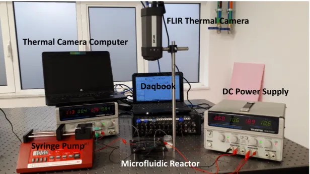
In addition to conventional batch reactor, two different configurations were utilized using microfluidic chips. Firstly, microfluidic chip in which dispersion medium was pumped continuously through channels using syringe pump (New Era type NE300, Farmingdale, NY, USA) was heated on hot plate as seen in
Figure 2.3. During polymerization, the temperature distribution on microfluidic chips was controlled by using a DAQ controller (IOTECH Daqbook/2000, Norton, MA, USA) and a thermal camera (FLIR A325sc, Sweden). Secondly, continuous flow microfluidic reactor with embedded electrodes was utilized to synthesize par-ticles. Instead of a hot plate, thin film heaters which provided control on temper-ature via voltage tuning was sputtered on opposite side of channels of microfluidic chip as shown in Figure 2.4. Flow control and temperature measurements were performed using the same equipment used in the hot plate configuration.
2.2
Design and Fabrication of Microfluidic
Re-actor
AIBN as a thermal initiator requires 55◦C to be activated. Dispersion solution has to be held at 70◦C to complete the polymerization. Hence, two different tem-perature zones are needed in microfluidic reactors. In addition, because of the fact that dispersion polymerization had two stages, two zones were created. Length of the particle growth stage which was second zone, designed three times of nuclei formation stage which was first zone. Based on the given requirements, the mold of microfluidic reactor was designed by Computer Aided Software SolidWorks. Technical drawing details of the mold are given in the Appendix. Total length of the channels is 1177 mm which consist of 272 mm first zone and 905 mm sec-ond zone. Micromachining was utilized to fabricate master mold in microfluidic systems. Aluminum mold was manufactured by a 3-axis micromachining cen-ter (PROINO Z3X Micro Maker, Mikro Protez Ltd.Sti., Ankara, Turkey). The fabricated mold is shown in Figure 2.2-A. The chip was fabricated using PDMS molding. After the fabrication, simple chemical cleaning, which is explained in Appendix, is used to clean aluminum mold. PDMS (Sylgard 184 Polydimethyl-siloxane, Dow Corning Midland, MI, USA) and curing agent was mixed in 10:1 by mass ratio and degassed under vacuum at room temperature. Following de-gassing, PDMS mixture was poured into the mold and degassed for 15 minutes. Then, the mixture was baked at 80◦C for 90 minutes. The cross linked PDMS
was gently peeled off with a knife from the mold. Two holes as an inlet and an outlet of the chip were punched out. As a substrate, microscope slide (Marienfeld Company) with a dimension of 76 mm×52 mm× 1 mm was used. Simple Chemi-cal Cleaning was employed. PDMS channels and glass substrate were bonded by using Nanoplas asher. Both surfaces are treated at 30◦C with an Oxygen flux of 25 sccm and Nitrogen flux of 5 sccm and RF power of 150 W for 1 minute. After the treatment, PDMS channels and glass substrate were bonded and kept in the oven at 80◦C for 10 minutes. PVC tubing which had 1.5 mm by 2.1 mm diameter was attached to inlet and outlet, and sealed by using PDMS (mixed in 5:1 by mass ratio). The structure seen in Figure 2.2-B shows the microfluidic chip. This chip was used in two different configurations for microparticle production. In the production on the hot plate, the chip was placed directly on the hot plate and no modifications was applied. However, as demonstrated in Figure 2.1, extra steps were required for the electrode embedded microfluidic chip to generate double zone configuration.
Figure 2.1: Demonstration of fabrication steps of microfluidic chip with embedded electrode
For electrode embedded reactor, before the asher step, the glass was cleaned using the simple chemical cleaning method. The thermal glass tape was adhered to the cleaned glass and the electrode was shaped. In Advance Research Lab-oratory, glass was coated with chromium using sputtering device (LH Leybold AG, L-560, Cologne, Germany). The electrodes were adjusted so that excessive
D
Figure 2.2: A) Fabricated aluminum mold, B) Microfluidic reactor for hot plate configuration, C) Fabricated microfluidic reactor with embedded electrode D) Microfuidic reactor covered with tape to increase thermal camera’s reading per-formance
heating at the connection points does not affect the channels. Cr-coated glass was bonded with PDMS channels via asher. PVC tubing was connected to the inlet and outlet of the chip and sealed. Then, the electrode wires were connected by Elecolit 325 (Panacol) conductive epoxy. The chip was baked at 50◦C for 2 hours to cure the epoxy. Then, using voltmeter, connections were verified and resistance values were checked. Final chip is presented in Figure 2.2-C.
FLIR Thermal
Camera
Thermal Camera Computer
Syringe Pump
Hot Plate
Figure 2.3: Experimental setup of microfluidic reactor on hot plate
2.3
Experiments
The dispersion mixture was consist of AIBN as an initiator, M-POSS as a monomer and PVP K-30 as a linear ionic stabilizer and SDS as a non-ionic surfactant in absolute ethanol as a dispersion medium. As proposed similar methacrylate studies such as in Bahar et al. [44], in beginning of the optimization, monomer concentration was determined as 5% of reaction medium then changed based on results. Syringe pumps were used to deliver the liquids at desired rates into the microfluidic devices. For microfluidic reactors, thermocouples and ther-mal camera were employed to monitor the temperature. For microfluidic reactor on the hot plate, the reaction temperature was set to 70◦C and microfluidic re-actor was placed near the edges since it was observed that hot plate surface did not have homogeneous temperature distribution. It was observed that the tem-perature varies 4◦C from center to edge. Experimental setup and components are shown in Figure 2.3.
DC Power Supply FLIR Thermal Camera
Daqbook Thermal Camera Computer
Syringe Pump
Microfluidic Reactor
Figure 2.4: Experimental setup of microfluidic reactor with integrated thin film electrode
As seen in the Figure 2.4, for microfluidic reactor with embedded electrode, temperature was gradually controlled from 50◦C to 70◦C. Voltage values were adjusted while feedback were collected via thermocouples and thermal camera. Then, the reacted liquids were collected into a 2 ml Eppendorf at the outlet of the microfluidic reactors.
The temperature controlled hotplate with a magnetic stirrer was used for con-ventional batch system polymerization. Five milliliters of dispersion mixture was put in flat bottom glass bottle with a magnetic stirring bar; and it was sealed and placed in an oil bath. The reaction took place on the hot plate for which the temperature was set to 70◦C. During the synthesis, magnetic stirring at 250 rpm for 6 h was employed. At the end of the synthesis in all three reactors, poly(M-POSS) was collected by centrifuge for 5 min at 10000 rpm. Resultant white-colored hybrid structures were washed with ethanol and DI water several times to remove unreacted medium and monomer. Finally, the particles were dispersed in 1% SDS containing DI water. Since in dispersion polymerization, all
agents have to be solvable in dispersion medium, EtOH was chosen as a solvent for POSS monomers. However, after the polymerization, poly(POSS) particles were not solvable in EtOH medium. Hence, after the washing process which includes EtOH dilution, the resultant chemicals are concluded to be poly(POSS).
2.4
Synthesis in Batch Reactor
First, the conventional batch technique was employed to obtain poly(M-POSS) microparticles. Generally, dispersion polymerization is useful to obtain uniform microparticles [44]. However, it was observed that the monomer methacryl POSS was not suitable to produce microparticles by dispersion polymerization in con-ventional batch reactor. The results obtained by this method are shown in Fig-ure 2.5. The synthesis in the conventional reactor was carried out in three different monomer ratios where the other parameters were kept constant. The constant parameters of reaction medium were 15 ml of absolute ethanol, 0.012 g PVP-K30 (0.1% w/w reaction medium), and 0.06 g AIBN (0.5% w/w reaction medium). The monomer amount was varied as 0.06 g (0.5% w/w reaction medium), 0.12 g (1.0% w/w reaction medium), and 0.24 g (2.0% w/w reaction medium) in Fig-ure 2.5. The prepared dispersion medium was magnetically stirred at 250 rpm at 70◦C for 6 h to complete polymerization. The nanocluster was obtained as shown in Figure 2.5-(A,B). Since the main aim of the study was achieving mi-croparticles, nanoclusters were not characterized in detail. It was observed that in Figure 2.5-(A,B), the size and shape of results were not microparticle. Al-though, in Figure 2.8-(C), surface chemical structural characteristics were similar to microfluidic reactor’s results, in Figure 2.9-(C), degradation profile were al-tered and in first step of degradation, temperature was higher than the results of microfluidic systems. These results suggested that in second stage of the disper-sion polymerization there was a problem, most likely due to type of the stabilizer. Additional bonds were formed, so resultant structure was not particle. Hence, the resultant structure was interpreted as nanocluster.
Figure 2.5: SEM image and morphological character of poly(M-POSS) obtained by dispersion polymerization with different momoner amounts: (A) 0.06 g POSS, (B) 0.12 g POSS, and (C) 0.24 g POSS in conventional batch reactor. (Reaction conditions: magnetically stirred at 70◦C for 6 h)
2.5
Synthesis in Microfluidic Reactors
The heating required to activate the initiator and complete the polymerization was provided in two different ways as shown in Figure 2.6. First, the microfluidic reactor was heated with embedded electrodes Figure 2.6-(A). As an alternative, the microfluidic reactor was placed on the hot plate that is at 70◦C Figure 2.6-(B). In the microfluidic reactor with embedded electrodes, two temperature zones were tuned by using thermocouple and thermal camera (FLIR, 325a). 50◦C and 70◦C heating zones are illustrated in Figure 2.6-(A). In the microfluidic reactor placed on the hot plate, two temperature zones were achieved, but in the first zone temperature was above the 60◦C. Desired distribution could not be achieved as seen in Figure 2.6-(B). Temperature distribution could not be controlled precisely due to restriction of the hot plate. If temperate was increased, in the second zone temperature would get higher and might cause droplet formation.
As seen in Figure 2.6-B, temperature of the right edge of the chip was slightly more than 70 ◦C since it was placed on the center of hot plate which is set to 70
(A) (B)
Figure 2.6: Thermal camera images of (A) electrode embedded microfluidic re-actor and (B) microfluidic rere-actor placed on hot plate
of the hot plate. It was observed that at the center, the temperature of hot plate was over 70◦C. From the center to the edge, the temperature was decreasing slightly and almost 4◦C observed via thermal camera. Hence, the temperature distribution in the chip was homogeneous whereas the chip was on the hot plate could not be controlled precisely. As discussed before, almost 20 ◦C was needed from the right edge to the left edge of the chip. So, the first zone of reactor was placed after the hot plate which enables the control via voltage supplied to the embedded electrodes, hence two temperature zones could be created on the chip. However, on electrical connection parts, increase in temperature was observed since heater was not designed properly. In Figure 2.6-A, it can be seen that the first zone on the chip was at desired temperature.
The center and corner of the hot plate was at different temperature ranges and the variation was around 4◦C. To obtain two different thermal regions in the microfluidic chip, the first zone of the reactor was placed at the corner of the hot plate and waited for steady-state to be reached for desired temperature in the second zone. Temperature of the second zone was more critical than the first one, since the reaction and dispersion fluid has restrictions like boiling point. This placement of the microfluidic reactor on the hot plate reduced the repeatability of
the experimental procedure. On the other hand, electrode embedded microfluidic reactors provided an opportunity to precisely control the temperature during the reactions repeatedly. The temperature of both zones could be controlled by changing voltage values. Each section was attached to the different DC power supplies sections as seen in Figure 2.4. The morphological character of poly(M-POSS) particles synthesized by using three different reactor types is given in Figure 2.7.
(A) (B) (C)
Figure 2.7: SEM images and EDX spectra of poly(M-POSS) synthesized in (A) microfluidic reactor placed on hot plate, (B) electrode embedded microfluidic reactor, and (C) conventional reactor
obtained using both of the microfluidic reactors. On the other hand, the con-ventional synthesis technique was not resulted in poly(M-POSS) microparticles. Although, magnetic stirring was sufficient for mixing the dispersion medium in the conventional reactor, it could not provide the required reaction control of the microreactor as opposed to the controlled mixing and heating in the mi-crofluidic systems. The structure of the synthesized poly(M-POSS) particles is characterized by FTIR and EDX. As seen in Figure 2.7, all synthesized forms of poly(M-POSS) have organic (carbon and oxygen content) and inorganic (silicon) part on their surface. The chemical bonds of hybrid structure are defined and specified by FTIR as seen in Figure 2.8 and Table 2.1. It can be clearly seen that the pattern of FTIR peaks is the same for all synthesized structures. The cage (Si–O–Si) structure of silica peak is in the range of 1200–1050 cm−1 and strong stretching in 1100 cm−1. The peak at 1730 cm−1 indicates C–O bonds, which comes from the methacrylate backbone of POSS on the poly(M-POSS) structure. The weak stretching vibration of C–H bonds is associated with the peaks at 2960–2890cm−1 [62].
Table 2.1: FTIR peaks of synthesized Poly(M-POSS) structures
The comparative thermal degradation behaviors of synthesized poly(M-POSS) structures are given in Figure 2.9. The thermal degradation profiles of the mi-croparticles synthesized by both of the microfluidic reactors are similar. The degradation process of poly(M-POSS) had three steps for all resultant products
Si-O-Si cage -C=O streching CH2 stretching Si-C CH2 out of bending (A) hot plate
(B) electrode embedded
(C) batch reactor
Figure 2.8: Surface chemical structural characterisitcs of synthesized poly(M-POSS) in (A) microfludic reactor placed on hotplate, (B) electrode embedded microfluidic reactor, and (C) batch reactor.
in any synthesis technique. Compared to poly(M-POSS) microparticles, the nan-ocluster form of poly(M-POSS) synthesized with the conventional batch system has higher degradation temperature for the first step of degradation. The ag-glomeration on nanocluster structures altered the initial degradation profile. This difference could be explained by having more inter molecular bonding in the nan-ocluster structure. All synthesized poly(M-POSS) have very sharp decreasing peaks at the second inflection point in Figure 2.9 at DTG curves. All forms of poly(M-POSS) begin to decompose and significantly loose more than 35% of their organic part between 350 and 450◦C. The specific point of degradation in which the weight loss reaches its maximum is nearly at 415◦C for the poly(M-POSS) structures synthesized by using the batch system and electrode embedded mi-crofluidic reactor. The poly(M-POSS) microparticles synthesized by using the microfluidic reactor placed on the hot plate have a degradation temperature of 419◦C. This degradation profiles are similar to those of POSS composites, which were studied in the literature.
(B) hot plate (A) batch reactor
(C) electrode embedded
Figure 2.9: TGA and DTG curves weight % loss of poly(M-POSS) structures synthesized in (A) batch reactor, (B) microfludic reactor placed on hotplate, and (C) electrode embedded microfluidic reactor.
The effect of initiator amount on the polymerization was analyzed by changing the mass ratio of AIBN while the other parameters were held constant as 0.125g POSS, 0.0125g PVP-K30 in 15ml dispersion medium. The initiator amount was changed as 0.03g, 0.06g, and 0.12g and was added to the prepared dispersion medium. The polymerization of each dispersion medium was performed within (i) the microfluidic reactor placed on the hotplate with a flow rate of 15µl/min: (ii) the microfluidic reactor with embedded electrodes with a flow rate of 90µl/min flow. After the polymerization, since the particles were insoluble in ethanol, the resultant medium was washed with ethanol to remove the unreacted reaction medium. Then the remaining product was washed with water and dispersed in 1% SDS containing DDI-water.
Figure 2.10: The morphological character of poly(M-POSS) microparticles while sweeping the initiator ratio(AIBN amount with respect to POSS amount by weight)(A) 25% (w/w), (B) 50% (w/w), (C) approximately equal amount to monomer. The microfluidic reactor placed on the hot plate (flow rate of 15µl/min) is represented as -15H and the microfluidic reactor with embedded electrode (flow rate of 90µl/min) is represented as -90E
As seen in Figure 2.10, the particle formation and size distribution change with the initiator amount. The spherical particle form begin to change towards nanoparticle form when the amount of initiator is increased in the microfluidic reactor placed on the hot plate. The reason of this change could be explained by the nature of the free radical polymerization mechanisms, and flow rate. Basi-cally, initiator attacked to the double bond (C=C) vinyl group of methacrylate part of POSS structure and created free radicals in the dispersion medium. Dur-ing the polymerization, these free radicals made bonds with each other in the microchannel. The increasing amount of the initiator creates more free radicals, which could increase the possibility of making bonds in the channel at reduced flow rates. The nanocluster form was obtained by increasing the amount of
Figure 2.11: The morphological character of poly(POSS) polymerization within the microfluidic reactor with embedded electrodes by changing the stabilizer ratio to dispersion (PVP K-30 amount with respect to dispersion medium by weight /volume): (A) 0.04% (w/v), (B) 0.075% (w/v), (C) 0.14% (w/v) while the other parameters held constant The microfluidic reactor placed on the hot plate (flow rate of 15µl/min) is represented as -15H and the microfluidic reactor with em-bedded electrode (flow rate of 90µl/min) is represented as -90E
initiator at slow flow rates in microfluidic system placed on the hot plate. In addition, few minutes later after the initiation of polymerization, the channels got clogged by the formed poly(M-POSS) nanoclusters due to the slow fluid flow (i.e. low drag force on the clusters) and hydrophobic interaction between PDMS and poly(M-POSS) in nanocluster form.
The effect of the stabilizer amount on the polymerization was analyzed by changing the mass ratio of PVP K-30 while the other parameters held constant. The constant parameters were prepared as 0.06g AIBN, 0.125g POSS in 15ml of dispersion medium. The initiator amount was changed as 0.006g, 0.0112g, and 0.022g and added to the prepared dispersion medium.
Figure 2.12: The morphological character of poly(M-POSS) microparticles while sweeping monomer ratio to dispersion (POSS amount with respect to dispersion medium by weight /volume):(A) 0.4% (w/v); (B) 0.8% (w/v), (C) 1.6% (w/v) while the other parameters held constant. The microfluidic reactor placed on the hot plate (flow rate of 15µl/min) is represented as -15H and the microfluidic reactor with embedded electrode (flow rate of 90µl/min) is represented as -90E
The particle form of poly(M-POSS) cannot be obtained by decreasing amount of stabilizer (PVP K30) as seen in Figure 2.11-A-15H and Figure 2.11-A-90E. Mostly, the characteristic of poly(M-POSS) structure was obtained in the form of nanowires because the free radicals created sticky ends and randomly bonded in the dispersion medium. Increasing of stabilizer provided a dispersion medium, which was suitable to generate particle shape poly(M-POSS) structure as seen in Figure 2.11-B-15H and Figure 2.11-B-90E. It was observed that the particle size got smaller and eventually form nanoclusters in the presence of high amount stabilizer as seen in Figure 2.11-C-15H and Figure 2.11-C-90E.
The effect of monomer amount on the polymerization was analyzed by changing the mass ratio of POSS while the other parameters held constant. The constant