Recovery of Hematite from The Coal Boiler’s
Bottom Ash by Column Flotation for Sponge Iron
Production
Yıldırım İ. Tosun
Mining Engineering Department, Şırnak University, Şırnak, Turkey
Abstract—
The total amount of asphaltite resource in reserves and production in Şırnak City are over 120 million tons of available asphaltite reserve and about 600 thousand tons per year, respectively. The asphaltite is used in mainly coal boilers for direct heating, and also in industrial furnaces as coal fine. The combusted asphaltite discarded as the boiler bottom ash contains 15% hematite at fine size from furnace
The most effective and cost-effective technologies are needed for iron ore products in today's modern technologies. Turkish pig iron industry needs sponge iron products and related technologies and high quality at lower cost with various types of local iron resources should be investigated.
In this investigation, a comparison was done between the use of poor hematite ores containing 15% hematite and the regional coal boiler bottom ash discarded as municipal waste 120 thousand tons per annum. The column flotation tests used oleic acid and pine oil as collector and frother to float hematite in the bottom ash, respectively. The flotation performances versus the amount of collector and pH ranged to 5 kg/t and 11, respectively, were determined as the reduced hematite recoveries of 63% and 45%. The less amount may resulted better (70% to 85%) hematite recoveries. In the tests of sponge iron production reductive roasting at 1000C with coal fine for different times, namely, 40 min, and 80 min of the hematite pellets were converted to sponge iron and the properties of the sponge iron ere determined. The burned coal in reductive roasting showed that volatile gases amount and quality affected on reductive roasting of hematite pellets to sponge iron. The iron oxide groups showed that the hematite quality will enhance the quality of sponge iron. Further reductive roasting provides much higher metal conversion.
Keywords: hematite flotation, bottom ash, lron production, iron ore, sponge lron,.
1. Introduction
The flotation routes of iron ore can be classified into five major groups, i.e. cationic flotation of iron oxide, cationic flotation of quartz, anionic flotation of iron oxide, anionic flotation of quartz [1,2]. Despite the variety of flotation routes developed for iron ores, currently, the reverse cationic flotation route developed as widely used flotation route in the iron ore industry. The two anionic flotation routes developed by Hanna Mining and Cyanamid, i.e. direct anionic flotation and reverse anionic flotation routes, are also being used in the iron ore industry.
The history of iron ore flotation started with direct flotation of iron oxides using anionic collectors such as petroleum sulphonate, fatty acids and hydroxymates. In 1950s, the direct flotation route was integrated in the plants. Theoretically, iron oxides should be easy to be separated from quartz in direct flotation. However, the presence of hydrolyzed cations in flotation pulp significantly reduces the selectivity of the direct flotation route. The easy hydrolysable cations in iron ore flotation pulp are generally calcium, magnesium and iron. Especially, these cations are either released into the flotation pulp from mineral particles or occur from hard water [1,2].
Although the reverse cationic flotation route has become the most popular flotation route in iron ore industry, the direct flotation of iron oxides still appears desirable for some low grade iron ores that contain a vast amount of quartz. For example, at Republic Mine, Michigan, U.S.A., a hematite ore is upgraded from 36.5% Fe to 65.4% Fe with a Fe recovery of 82.5% using the direct flotation route. Fatty acids (a distilled tall oil containing approximately 91% oleic and linoleic acids) are used as the collector of iron oxides, the dosage of which is usually in the range of 0.45-0.67 kg/t [3,4, 5]. Conditioning was reported to be of critical importance for the direct flotation process. Intense conditioning can reduce reagent cost as much as 50%. Prolonged conditioning was also found beneficial to the direct flotation route but was not economically justified [3].
The adsorption of fatty acids on hematite plays a key role in the direct flotation route. In the literature, it is generally accepted that fatty acids adsorb on the surfaces of hematite through chemical bonding. Based on infrared studies, established that oleic acid/sodium oleate chemisorbs on hematite [4]. Using the technique of micro electrophoresis, demonstrated the chemisorptions of oleic acid and lauric acid on hematite [5]. It is also confirmed chemisorption of lauric acid on hematite surfaces [6]. In addition to chemisorption, fatty acids can also adsorb on mineral surfaces through surface precipitation [7, 8].
It is mainly found that hydroxamates, which behave similarly to fatty acids in solution [9], were used successfully in the laboratory as collectors for hematite and goethite flotation, with better performance than fatty acids [10, 11]. The adsorption mechanism of hydroxamates on hematite was classified as classical chemisorptions [5, 12].
In the reverse cationic flotation, the depressant of iron oxides that is widely used is typically corn starch. Corn starch is not soluble in cold water and must be put into solution in a process known as gelatinization. Starch gelatinization can be realized by thermal gelatinization or alkali gelatinization. The physicochemical fundamentals of starch gelatinization are still not fully understood and different theories have arisen [13]. In the thermal gelatinization process, it is generally agreed that as temperature increases starch molecules vibrate more vigorously, thus breaking the intermolecular hydrogen bond and allowing penetration of water [14]. In the iron ore processing industry, thermal gelatinization has become less popular due to the hazards of employing hot water [15] and the associated energy cost in heating. In comparison with thermal starch gelatinization, much less is known about alkali gelatinization [15].
Humphrey spirals were also used in the washing of ash and hematite in the high and medium intensity and especially in the washing of the pyritic sulfur in the coal is preferred widely [18,19,20,21]. In the high density and high ash coals Humphrey spirals in a specific amount during the washing was observed to increase the amount of mixed product.
1.1. Washing with the Column Flotation
Column flotation of fine coal is determined could very well yield can be floated in the microbubbles [22, 23]. Microbubble washing water in the form of shower foam zones consisting of may be possible to obtain cleaner product [24, 25]. Particularly, for difficult washable shale and shale column is a method used successfully in flotation at high rates [26]. Particle size and type of coal as the flotation column can easily affect efficiency. However, operating parameters, especially the foam height of the column unit, the wash water is added, and the bias ratio is flammable operating parameters affect efficiency. [22, 23,27].
It was formed on an inclined foam zone to increase the effectiveness of the foam. with the effect that gravity is stated to reduce drift foam. This essential principles laid cyclonic column flotation cell (S-FCMC) provided a foam zone
comprising inclined channels (FCMC) it proved to be effective in coal washing and widely China [27, 28] was used. the foam product has a third zone of the foam sediment are removed [27].
The application of column cells in the mineral processing industry has gone from virtually zero in 1983 to wide acceptance in 1990 [22-27]. The major operating difference between column flotation cells and mechanical flotation cells is the lack of agitation in column flotation which reduces energy and maintenance costs [23]. The practice of froth washing in direct flotation increases concentrate grades without significant recovery losses [24]. In the reverse flotation of iron ores, froth washing was found effective in reducing the loss of fine iron oxide particles to froth. It was reported that the cost of installing a column flotation circuit is approximately 25% - 40% less than an equivalent flotation circuit of mechanical flotation cells [16].
However, negative reports on the use of column cells were also found in the literature [16,17]. there were several failures in the application of column cells in the iron ore industry [16]. following three column flotation stages, of rougher, cleaner and re-cleaner, a secondary circuit of mechanical cells was still operated to produce the final concentrate.
2. Material and Methods
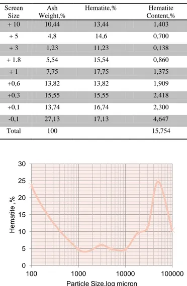
The bottom ash of Avgamasya vein asphaltites represent approximately 67% of the production is carried out from the coal mines has been reduced to 120 kg sample cone reduced by up to 18mm-fours under the hammer. Nuts are widely washed coal ash and high sulfur coal to be sold as industrial fuel asphaltites is intended to be sold. Optimum bottom ash flotation plant is determined by standard testing results performed. In the experiments, the bottom ash of Avgamasya vein asphaltites was crushed and screened prior to represent flotation samples and distribution of fractional ash is given in Table 1. Figure 1 hematite distrubition and ash size distribution were described. Large and medium-sized ash content is more intense, it was reduced in particle size. Especially the range below 10 mm cumulative hematite remained about 21,3 %. The hematite percentage was 21,3% in this distribution. It showed uniform distribution of the hematite content in all fractions.
3. Results and Discussion
3.1 Direct Flotation of Hematite in Bottom ash of Asphaltite
30 kg samples were ground to -0,3mm in ball mill and 1kg representative samples were used in the study represent – 0,3mm size of -0,1mm separated flotation tests for grain size fractions were subjecte direct flotation made by oleic acid.. In the direct flotation test; oleic acid at neutral pH solution were used as collector. – 0,1 mm fraction used in this study were studied in similar way.
Table 1. The cumulative distribution of Hematite at Bottom Ash Particle Size and Hematite content in Ash
Screen Size Ash Weight,% Hematite,% Hematite Content,% + 10 10,44 13,44 1,403 + 5 4,8 14,6 0,700 + 3 1,23 11,23 0,138 + 1.8 5,54 15,54 0,860 + 1 7,75 17,75 1,375 +0,6 13,82 13,82 1,909 +0,3 15,55 15,55 2,418 +0,1 13,74 16,74 2,300 -0,1 27,13 17,13 4,647 Total 100
15,754
Figure 1. Distribution of Hematite in the Bottom Ash versus Particle Size
1 liter Denver laboratory flotation cell for hematite flotation tests were used to produce mixed and waste products. 3 min 3 min in duration and fitness testing coal, flotation time was used for 2min mixed. 20% solids / IV ratio was studied in a mixing speed 1500rpm. Hematite flotation tests, oleic acid 300 g / ton MIBC 400 g / t conditioned
According to the results of the flotation made one class; -0,3 mm grain obtained by calculating the cumulative classes test results are given in Table 2. Hematite grade and yields were the data in these tables are described in Figure 2 with the curve.
Figure 2. Test Values in Hematite yields in- 0.3 mm grain Fraction against pH (Bottom ash by weight of 26.3%, 65.7% of ash slime)
Hematite concentrate can be floated in a weight ratio of 58.2%. 59.7% iron grade hematite can be floated in a weight ratio of 68.2% concentration. This identifies that has a heavy concentration such as a table is determined to be effective.
26.3% by weight of the ash floated is observed with the 57.5% yield of hematite could be recovered as given 28.4% as given in Table 3 .
Figure 3. Test Values in Hematite yields in- 0.3 mm grain Class by time (Bottom ash by weight of 26.3%, 65.7% of ash slime)
Hematite can be washed with some weighing as high as 17.9% when the hematite and ash slimes on hematite flotation for 42.3% constituting 0.02 mm grain size flotation yields were obtained. This is thought to be caused by slime cover content. However, shale and ash slime have also been coupled in parallel as hematite product. The cumulative result of the mixed obtained from the test; 76.5% side with an efficiency of 28.4% can be recovered as slime product is seen from Table 3.
3.2 Washing with the Column Flotation
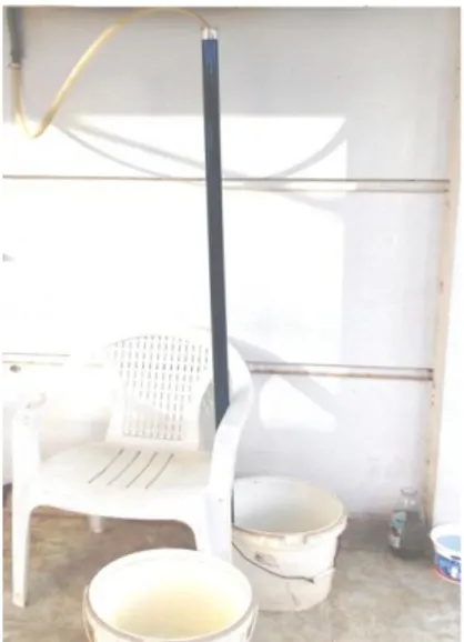
Representation of -0.5 mm samples are reduced to grinding -100mikro controlled size. 1 m glass column 3 cm in
0 20 40 60 80 100 0 2 4 6 8 10 H e m atite Yi e ld ,% pH Hematite Yield.% Polinom. (Hematite … 0 20 40 60 80 100 0 10 20 30 H e m atite Yi e ld ,%
Flotation Time, min
Iron Content,% Hematite Yield% 0 5 10 15 20 25 30 100 1000 10000 100000 Hem a ti te ,%
diameter laboratory column cell flotation cell used in the column flotation of bottom ash (Figure 4)
Figure 4 Column Flotation Equipment System of Şırnak Bottom ash
The reagents used in conventional flotation column flotation tests were also performed in the column tests. In the column flotation tests oleic acid 300 g / ton MIBC 400 g / t were conditioned foam height is kept constant at 30 cm. Zero Bias ratio is used to produce clean coal and shale waste products. The flotation time was used for 3 min and 35 min time condition coal in tests. 20% solid/liquid ratios of 200 ml/min were studied in the wash water.
Column flotation tests results from hematite concentrate, shale waste can be taken as sink bottom product and hematite yield equilibrium distribution is given in Table 5. Accordingly (-100microns) mm grain size in bottom ash is mixed with slime hematite can be as 60.60% in cumulative yield will be thrown when recovered hematite is contained, 54.3% iron content of the ash and bottom tailings contained 4% iron as waste (Figure 4).
Column Flotation efficiency of hematite products produced from the results of tests of the direct flotation to 77% of hematite yield has fallen 64% value. Flotation test results produced for the hematite product yields from 77% to 64% of the iron content has fallen 45% value (Figure 4). As shown in Figure 5 The iron contents produced from test results of 42% decreased to value of 37% for the column flotation of bottom ash. The product yields has been lower compared to other methods.
Figure 5. Test Values in Hematite yields in- 0.1 mm grain Fraction Column Flotation Test Values (Bottom ash by
weight of 10.7%, and 35.2% of the ash slime)
4. Proposed Project Design
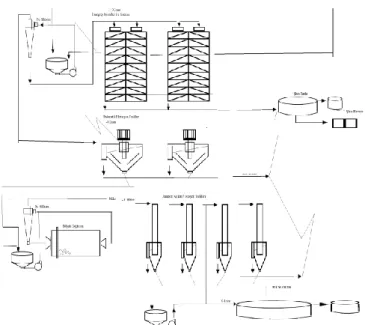
For iron ore concentration, heavy medium washing large boat in or drum widely used, the fine coal (18-1mm) in size are considered heavy media cyclone unit (Anonymous, b, c, 2015). Şırnak bottom ash the washing of these units Larcodems or fine ash washing unit that uses Humphrey spirals in mind it would be useful wash plant designs are made for efficiency cannot be achieved. According to the above washing test results it was analyzed in terms of investment and operating costs of the following two different designs. Implementing the flotation column with ash hematite flotation plant design also includes units shown in Figure 5. The B design that uses only hematite flotation unit is shown in Figure 6.
Design Facility mainly heavy media cyclones, Humphrey spirals, pneumatic flotation unit Tables and Jameson / Wemco column includes a flotation unit. The recently developed high-performance column flotation units in the slime coal washing, used with success (Anonymous, b, c, 2015). Hematite concentration plant flow diagram is as shown below for the B design.
Figure 6. A flow chart of the Project Design Hematite Flotation plant 0 10 20 30 40 50 60 70 0 10 20 30 40 H e m atite Yi e ld ,%
Flotation Tme, min
İron Content,% Hemtite Yield,%
Hematiye yields of 70-74% from the bottom ash flotation may be efficiently recovered in the proposed washing plant. This plant capacity of 1 million tons/year can be operated with that production capacity more than 60 years. In the proposed design of the hematite flotation plant, sponge iron was capable of iron grade in the plant, as sponge iron (19-10 mm) 350 000 tons, industrial 80% iron grade may produced with fuel (-10 / -0.5 mm) of 20 000 tons, as the washed 165 000 tons of sponge iron was proposed be produced.
Figure 7. A flow chart of the Project Design Hematite Flotation plant
This facility will produce 100 000 tons of hematite, around from 250 000 tons of bottom ash. as waste of boilers used for heating in Şırnak yielded 12 million $ and cost of transportation is about 5$/ton. 65 million $ investment cost of this facility may return back as investment capital in 2 years, current bank interest rates (7%) and will be produced annually 100 thousand tons of hematite and 135 thousand tons of low grade iron ore, total annual operating costs 19.32 $per / ton and washing costs approximately £ 60.68/ton of hematite in the plant would be calculated (Figure 6).
5. Conclusions
Due to the iron content of Şırnak asphaltites and show that conventional flotation can be effective as column flotation. The yield was also determined not reduced sufficiently, as well as hematite product can be 56% . The recovery of hematite was 87% in the hematite flotation plant. The recovery in column flotation can be reduced to 68% of the bottom ash disposed.
Hematite content of the bottom ash was suitable for evaluation in sponge iron production so that the sponge product will provide benefits in terms of reduced costs as well as transport and environmental protection. The lower grade
value can be both beneficial in recovery and capacity for industrial iron produced.
In the proposed design of the hematite flotation plant, sponge iron was capable of iron grade in the plant, as sponge iron (19-10 mm) 350 000 tons, industrial 80% iron grade may produced with fuel (-10 / -0.5 mm) of 20 000 tons, as the washed 165 000 tons of sponge iron was proposed be produced.
References
[1] Krishnan, S.V., Iwasaki, I., 1984. Pulp dispersion in selective desliming of iron ores. Int. J. Miner. Process. 12, 1-13.
[2] DeVaney, F.D., 1985. Iron Ore. In: Weiss, N.L. (Ed.), SME Mineral Processing Handbook, American Institute of Mining, Metallurgical and Petroleum Engineers, New York.
[3] Yang, D.C., 1988. Reagents in Iron Ore Processing. In: Somasundaran, P. and Moudgil, B.M., (Eds.), Reagents in Mineral Technology, Marcel Dekker Inc., New York, pp. 579-644.
[4] Peck, A.S., Raby, L.H., Wadsworth, M.E., 1966. An infrared study of the flotation of hematite with oleic acid and sodium oleate. Trans. AIME 235, 301-307.
[5] Han, K.N., Healy, T.W., Fuerstenau, D.W., 1973. The mechanism of adsorption of fatty acids and other surfactants at the oxide-water interface. J. Colloid Interface Sci. 44, 407-414.
[6] Buckland, A.D., Rochester, C.H., Topham, S.A., 1980. Infrared study of the adsorption of carboxylic acids on hematite and goethite immersed in carbon tetrachloride. Faraday Trans. I 76, 302-313.
[7] Somasundaran, P., Huang, L., 2000. Adsorption and aggregation of surfactants and their mixtures at solid/liquid interfaces. Adv. Colloid Interface Sci. 88, 179-208.
[8] Zhang, R., Somasundaran, P., 2006. Advances in adsorption of surfactants and their mixtures at solid/solution interfaces. Adv. Colloid Interface Sci.123, 213–229.
[9] Bulatovic, S.M., 2007. Handbook of Flotation Reagents, Elsevier, Amsterdam.
[10] Fuerstenau, M.C., Miller, J.D., Gutierrez, G., 1967. Selective flotation of iron ore. Trans. AIME 238, 200-203. [11] Fuerstenau, M.C., Harper, R.W., Miller, J.D., 1970.
Hydroxamate vs. fatty acid flotation of iron oxide. Trans. AIME 247, 69-73.
[12] Raghavan, S., Fuerstenau, D.W., 1974. The adsorption of aqueous octylhydroxamte on ferric oxide. J. Colloid Interface Sci. 50, 319-330.
[13] Papini, R.M., Brandão, P.R.G., Peres, A.E.C., 2001. Cationic flotation of iron ores: amine characterisation and performance. Minerals & Metallurgical Processing 17, 1– 5.
[14] Vidyadhar, A., Hanumantha Rao, K., Chernyshova, I.V., Pradip, Forssberg, K.S.E., 2002. Mechanisms of amine–quartz interaction in the absence and presence of
alcohols studied by spectroscopic methods. J. Colloid Interface Sci. 256, 59–72.
[15] Yamamoto, H., Makita, E., Oki, Y., Otani, M., 2006. Flow characteristics and gelatinization kinetics of rice starch under strong alkali conditions. Food Hydrocolloid. 20, 9-20.
[16] Dobby, G., 2002. Column Flotation. In: Mular, A.L., Halbe, D.N. and Barratt, D.J. (Eds.), Mineral Processing Plant Design, Practice and Control, SME Inc., Littleton. [17] Peres, A.E.C., Araujo, A.C., Shall, H., Zhang, P.,
Abdel-Khalek, N.A., 2007. Plant practice: nonsulfide minerals. In: Fuerstenau, M.C., Jameson, G., Yoon, R-H (Eds.), Froth Flotation – A Century of Innovation, SME, Littleton.
[18] Anonim a, 2015, Multotec Şirket web sayfası,
http://www.multotec.com/category/ industry/coal
[19] Anonim b, 2015, MBE Şirket web sayfası,
http://www.mbe-cmt.com/en/products/pneuflot% C2%
AE/pneuflot%C2%AE
[20] Anonim c, 2015, CWP Şirket web sayfası,
http://cwp.com.tr/en/products.aspx?id=30
[21] DPT, 2007, Dokuzuncu Kalkınma Planı, Devlet Planlama Teşkilatı Madencilik Özel İhtisas Komisyonu Raporu, Ankara.
[22] Finch J.A., Dobby,G.S.(Eds), 1990, Column Flotation, Pergamon Press, Toronto
[23] Hadler, K., M. Greyling, N. Plint, and J. J. Cilliers. 2012. The effect of froth depth on air recovery and flotation performance. Minerals Engineering 36: 248–253. [24] Jameson , G. J. 2001 . The flotation of coarse and ultrafine particles . International Journal of Mineral Processing 72 : 12 – 15
[25] Yoon, R. H. 1993. Microbubble flotation. Minerals Engineering 6(6): 619–630.
[26] Yoon, R. H. 2000. The role of hydrodynamic and surface forces in bubble–particle interaction. International Journal of Mineral Processing 58(1): 129–143.
[27] Yianatos, J. B., J. A. Finch, and A. R. Laplante. 1988. Selectivity in column flotation froths. International Journal of Mineral Processing 23(3): 279–292.
[28] Rubio, J. 1996. Modified column flotation of mineral particles. International Journal of Mineral Processing 48(3): 183–196