A THESIS
SUBMITTED TO THE DEPARTMENT OF COMPUTER ENGINEERING AND THE INSTITUTE OF ENGINEERING AND SCIENCE
OF B˙ILKENT UNIVERSITY
IN PARTIAL FULFILLMENT OF THE REQUIREMENTS FOR THE DEGREE OF
MASTER OF SCIENCE
By
M. Adil Yalc.ın
June, 2010
Prof. Dr. B¨ulent ¨Ozg¨uc. (Advisor)
I certify that I have read this thesis and that in my opinion it is fully adequate, in scope and in quality, as a thesis for the degree of Master of Science.
Asst. Prof. Dr. Tolga C. apın (Co-Advisor)
I certify that I have read this thesis and that in my opinion it is fully adequate, in scope and in quality, as a thesis for the degree of Master of Science.
Assoc. Prof. Dr. Uˇgur G¨ud¨ukbay
I certify that I have read this thesis and that in my opinion it is fully adequate, in scope and in quality, as a thesis for the degree of Master of Science.
Assoc. Prof. Dr. Veysi ˙I¸sler
Approved for the Institute of Engineering and Science:
Prof. Dr. Mehmet B. Baray Director of the Institute
DEFORMATIONS ON HEIGHTFIELDS
M. Adil Yalc.ın
M.S. in Computer Engineering Supervisor: Prof. Dr. B¨ulent ¨Ozg¨uc.
Co-Supervisor: Asst. Prof. Dr. Tolga C. apın
June, 2010
The applications of computer graphics raise new expectations, such as realis-tic rendering, real-time dynamic scenes and physically correct simulations. The aim of this thesis is to investigate these problems on the heightfield structure, an extended 2D model that can be processed efficiently by data-parallel architec-tures. This thesis presents methods for simulation of deformations on heightfield as caused by triangular objects, physical simulation of objects interacting with heightfield and advanced visualization of deformations. The heightfield is stored in two different resolutions to support fast rendering and precise physical simula-tions as required. The methods are implemented as part of a large-scale height-field management system, which applies additional level of detail and culling optimizations for the proposed methods and data structures. The solutions pro-vide real-time interaction and recent graphics hardware (GPU) capabilities are utilized to achieve real-time results. All the methods described in this thesis are demonstrated by a sample application and performance characteristics and results are presented to support the conclusions.
Keywords: Computer graphics, computer animation, physical simulation, height-fields, deformations.
DE ˘
G˙IS
¸T˙IRMELER˙IN GERC
¸ EK-ZAMANLI
S˙IM ¨
ULASYONU VE G ¨
ORSELLES
¸T˙IR˙ILMES˙I
M. Adil Yalc.ın
Bilgisayar M¨uhendisli˘gi, Y¨uksek Lisans Tez Y¨oneticisi: Prof. Dr. B¨ulent ¨Ozg¨uc.
Tez Yardımcı Y¨oneticisi: Asst. Prof. Dr. Tolga C. apın Haziran, 2010
Bilgisayar grafi˘gi uygulamaları ger¸cek¸ci g¨orselle¸stirme, ger¸cek-zamanlı
di-namik ortamlar ve fiziksel olarak modellenmi¸s nesnelerin sim¨ulasyonu gibi
gereksinimleri de barındırmaktadır. Bu tezin amacı, s¨oz konusu problemleri
y¨ukseklik haritası modeli ¨uzerinde ara¸stırmaktır. Y¨ukseklik haritası, geni¸sletilmi¸s 2 boyutlu bir modeldir ve bu model, veri-paralel bilgisayar mimarilerinde ver-imli ¸sekilde i¸slenebilmektedir. Bu tez, ¨u¸cgensel objelerin etkisiyle olu¸san y¨
uksek-lik haritaları ¨uzerindeki bozulmaların simulasyonu, objelerin y¨ukseklik haritası
¨
uzerinde fiziksel simulasyonu ve ¸seklen bozulmu¸s b¨olgelerin ileri g¨orselle¸stirilmesi
konularında y¨ontemler sunmaktadır. Hızlı g¨orselle¸stirme ve daha kararlı
fizik-sel simulasyon elde etmek amacıyla, y¨ukseklik haritası, iki farklı ¸c¨oz¨un¨url¨ukte saklanmaktadır. Sunulan y¨ontemler, geni¸s ¨ol¸cekli bir y¨ukseklik haritası y¨ one-tim sisteminin par¸caları olarak ger¸ceklenmi¸s olup, ek olarak detay seviyesi ve optimizayson algoritmaları da i¸cermektedir. Sonu¸clar, ger¸cek-zamanlı etkile¸sime
olanak tanımakta ve g¨uncel grafik i¸sleme donanımları (GPU), ger¸cek-zamanlı
sonu¸clar alınmasına yardımcı olmaktadır. Bu tezde tanımlanan y¨ontemler, ¨ornek
bir uygulamayla g¨osterilmekte ve varılan sonu¸cları do˘grulamak ¨uzere performans
deˇgerlendirmeleri sunulmaktadır.
Anahtar s¨ozc¨ukler : Bilgisayar Grafiˇgi, Bilgisayar Animasyonu, Fiziksel
Simu-lasyon, Y¨ukseklik Haritası, Geometrik Deformasyon.
First and foremost, this thesis would not have been possible without the care and support of my mother and the protection of my father.
I thank Damla Arifoˇglu for standing by my side in my good and bad days,
her support and love have been invaluable. My friend Mehmet Koc.akoˇglu has been like a brother to me since I have known him, lending a hand and a mind when I was in need. I also want to thank my friends from Middle East Technical University and Bilkent University (Bahadır, Caner, ˙Ilkay and others) with whom
I shared valuable times. I am grateful to my friends Sefa and Doˇga for letting me
use their PC (PC1) for testing the sample application.
I feel privileged to have worked with my advisors through the course of my
M.Sc. studies. I thank B¨ulent ¨Ozg¨uc. for making research so fun and exciting.
I learned so much from his vision and my conversations with him have always
been rewarding. I thank Tolga C. apın for supporting my dreams and always
valuing my ideas, whether they may be right or not. He has provided me an environment in which I could develop my skills and thus the methods presented in this thesis. I also want to thank the members of the thesis jury, Uˇgur G¨ud¨ukbay and Veysi ˙I¸sler for evaluating the thesis and providing their feedback. Moreover, they have introduced me various problem domains of computer graphics within their courses, which I loved to attend as a student.
I want to express my sincere thanks to all the people around the world who have contributed to the open global knowledge. This spans not only the contrib-utors of the open source software libraries that have been used in this thesis, but also contributers of all open source libraries and all open and reliable information sources and arts in many forms. And lastly, I want to thank many talented and open minded, independent musicians for making the atmosphere a better place to live in with their unique sound vibrations.
My M.Sc. studies have been financially supported by T ¨UB˙ITAK (The
Scien-tific and Technological Research Council of Turkey) B IDEB scholarship and also partly by European Union through 3DPHONE project.
1 Introduction 1
1.1 Motivation . . . 2
1.2 Challenges . . . 3
1.3 Overview of the System . . . 4
1.4 Summary of Contributions . . . 6
1.5 Structure of the Thesis . . . 7
2 Background and Related Work 8 2.1 Methods for Heightfield Structures . . . 8
2.1.1 Deformations . . . 8
2.1.2 Erosion . . . 10
2.1.3 Level Of Detail . . . 11
2.1.4 Surface Details with Heightfields . . . 12
2.2 Collision Detection and Physical Simulation on GPU . . . 15
3 Data Structures 17 3.1 Heightfield Data Basics . . . 17
3.2 Data Managed on CPU . . . 21
3.2.1 Terrain Patch and Quad-tree Structure . . . 21
3.2.2 Terrain Sub-Patch . . . 22
3.2.3 Index Buffer Management . . . 23
3.2.4 Terrain Attribute Images . . . 24
3.3 Data Managed on GPU . . . 25
3.3.1 Heightfield Vertex Displacement Maps . . . 25
3.3.2 Storage of Heightfield Normals . . . 27
3.3.3 Generation of Heightfield Normals . . . 29
3.3.4 Collision Buffers . . . 30
4 Deformation Algorithms for Heightfields 32 4.1 Collision Detection and Heightfield Compression . . . 33
4.1.1 Broad Phase Collision Detection . . . 34
4.1.2 Narrow Phase Object Collision Data Generation . . . 35
4.1.3 Narrow Phase Exact Collision Detection and Compression 37 4.1.4 Narrow-Phase Culling for Collision Processing . . . 39
4.2 Decompression . . . 41
4.2.1 Local Linear-Speed Decompression Model . . . 42
4.2.2 Local Exponential-Speed Decompression Model . . . 43
4.2.3 Erosion Decompression Model . . . 44
5.1 Physical Simulation Engine Wrapper Layer . . . 47
5.2 Generating Contacts from Collision and Heightfield Data . . . 49
6 Heightfield Visualization 52 6.1 Low-Resolution Level-Of-Detail and Culling . . . 52
6.1.1 Geo-Mipmapping Level-Of-Detail . . . 53
6.1.2 Generating Geo-Mipmapped Index Data for Heightfield Blocks . . . 56
6.1.3 Terrain Patch and Primitive Culling Optimizations . . . . 59
6.2 GPU Shading for Visualization . . . 62
6.2.1 Generation of Vertex Geometry . . . 63
6.2.2 Heightfield Texturing and Lighting . . . 65
6.2.3 Two-Step Sub-Patch Rendering for Deformed Patches . . . 67
6.2.4 Single-Step Rendering for Deformed Patches . . . 68
6.2.4.1 Simple Shading . . . 69
6.2.4.2 Adaptive Normal Mapping . . . 69
6.2.4.3 Adaptive Parallax Mapping . . . 69
6.2.4.4 Additional Discussions on Single-Step Renderers . 71 6.2.4.5 Adaptive Shading Deformed and Undeformed Cell Blending . . . 71
6.2.5 Deformation Shading Enhancements . . . 72
7 Implementation and Performance 76
7.1 Scene Setup . . . 76
7.1.1 Generating Procedural Terrains . . . 78
7.1.2 Rendering Engine Implementation . . . 79
7.2 Performance . . . 79
7.2.1 Performance Overview . . . 80
7.2.2 Heightfield Collision Detection and Simulation Performance 82 7.2.3 Heightfield Visualization Performance . . . 86
7.2.4 Rigid Body Simulation Performance . . . 89
8 Conclusions and Discussions 93 8.1 Conclusions . . . 93
8.2 Future Work . . . 94
A GPU Shaders and Additional Figures 97 A.1 Object Collision Data Generator OpenGL Program . . . 97
A.2 Heightfield Normal Generator OpenGL Program . . . 98
A.3 Heightfield Rendering OpenGL Program . . . 101
A.4 Additional Figures and Images . . . 111
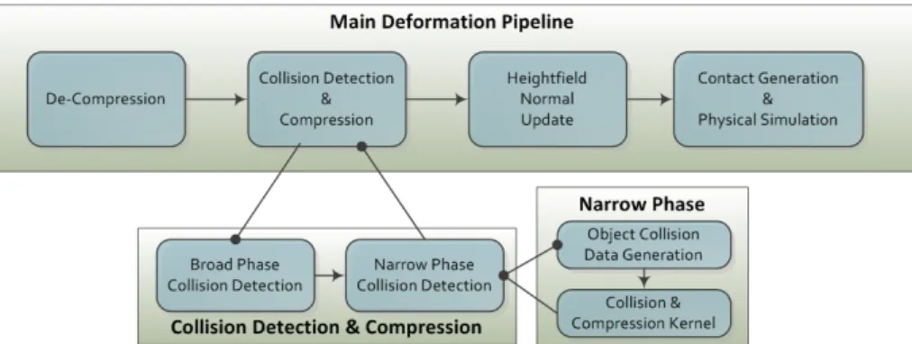
1.1 The Basic Deformation Pipeline . . . 5
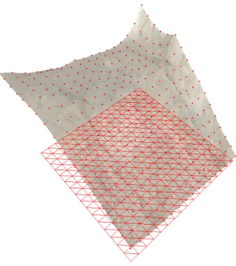
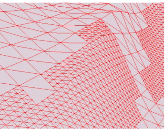
3.1 A heightfield point and wireframe rendering on its 2D grid base . 18 3.2 Visualization of mixed low-resolution and high-resolution data (as created by triangular interpolation). . . 19
3.3 A sample small terrain configuration, including 6 sub-patches . . . 23
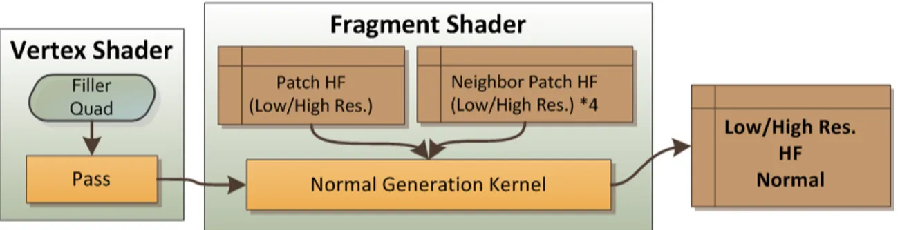
3.4 Data flow diagram for generating high/low resolution normals . . 30
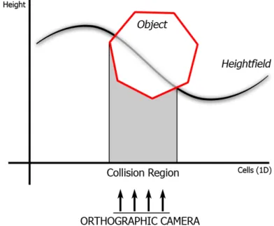
4.1 The identification of colliding cells on a 1D heightfield . . . 34
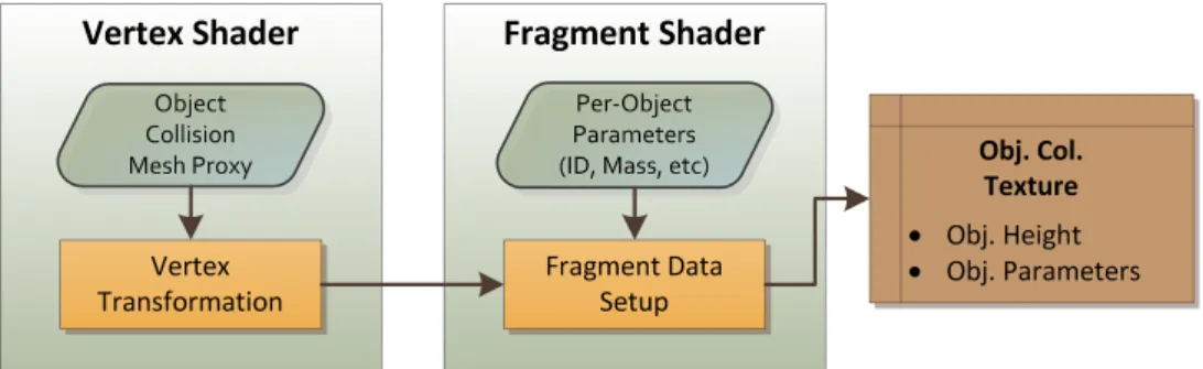
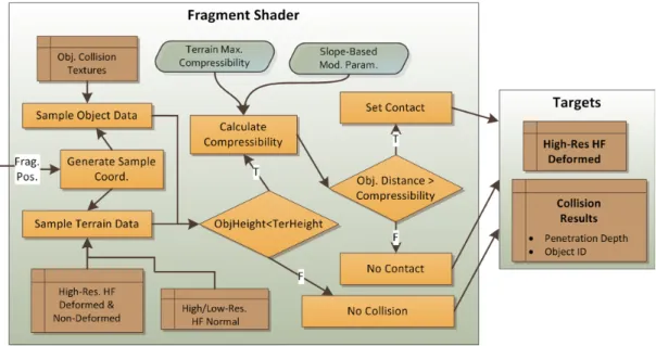
4.2 Object Collision Data Generator Program Data Flow Diagram . 36 4.3 Collision and Compression Data Flow Diagram . . . 37
4.4 The Narrow-Phase Culling De-Synchronization Problem . . . 41
4.5 Local Decompression Models . . . 44
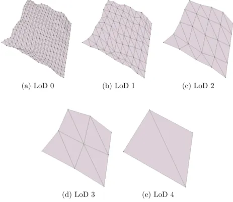
6.1 Geo-mipmapped layers of a sample heightfield block . . . 54
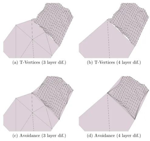
6.2 Visible and avoided T-Vertices between different detail layers . . . 56
6.3 Complex triangle strips data of a heightfield block . . . 58
6.4 Patch-Bound Occlusion Culling in 1D . . . 60
6.5 Unified Rendering Vertex Shader . . . 63
6.6 Unified Rendering Fragment Shader . . . 64
6.7 A deformed terrain patch with deformed and affected samples. . . 72
7.1 Procedural Terrain Generation User Interface . . . 78
A.1 Sub-patch rendering applied to a deformed terrain patch . . . 111
A.2 Rendering of sharp features on deformed regions . . . 112
A.3 The shading models for rendering deformed patches . . . 113
A.4 The effect of applying deformation enhancements . . . 113
A.5 Quad-Tree AABB’s of a sample heightfield . . . 114
A.6 3D Frustum culling applied to terrain patches . . . 114
A.7 The object models that have been used to test the collision and compression pipeline . . . 115
A.8 Resting objects on the ground, with their collision and contact geometries . . . 115
A.9 The closer view of contact points and contact normals generated by a sphere-terrain intersection . . . 116
A.10 Comparison of high and low resolution tessellations with interfering scene objects . . . 116
6.1 Triangulation performance of the index data generator
implemen-tation . . . 59
6.2 Comparison of deformation rendering methods . . . 74
7.1 Test PC configurations . . . 81
7.2 Basic frame time performances (in ms) for a typical scene
config-uration . . . 82
7.3 Heightfield simulation performance overview (in ms) . . . 83
7.4 Heightfield GPU simulation performance (in ms) wrt. collision
buffer configurations . . . 84
7.5 Heightfield decompression models performance . . . 85
7.6 Heightfield collision and compression kernel performance ith
re-spect to hardware . . . 85
7.7 Heightfield object collision data generation performance . . . 86
7.8 Visualization performance (undeformed) overview (in ms) . . . 87
7.9 Visualization FPS performance (undeformed) wrt. terrain render
config. . . 88
7.10 Visualization performance (deformed) overview . . . 89
7.11 Rigid Body Simulation Performance . . . 90
Introduction
Heightfield, also commonly called heightmap or terrain, is one of the basic graphi-cal structures that is commonly used in virtual 3D scenes. Heightfield is a uniform discrete grid-based structure, in which each cell holds a relative height informa-tion with respect to a ground height level. Thus, this structure especially fits well into outdoor scenes to provide a basic solid world geometry, such as valleys, mountains, hills, cliffs and smaller perturbations on ground. Other scene ob-jects, such as vegetation, characters and vehicles, are generally placed upon this graphical structure. Heightfields can also be utilized and exploited in texturing techniques. Their uniform grid-based structure further allows solving computa-tionally complex problems more efficiently, including collision detection.
While there exists extensive research on heightfields, mostly in rendering opti-mizations (such as continuous or discrete level-of-detail systems), shading (includ-ing shadow(includ-ing), procedural generation and erosion models [47, 2], there currently exist no real-time and scalable architecture to support physical interactions be-tween arbitrary 3D objects and heightfield structures. This thesis aims to provide a system which considers collision detection, physical simulation, level-of-detail optimizations, rendering and editing problems as a whole. The proposed system is designed to work efficiently on recent parallel GPU architectures, a hardware ded-icated to graphic processing, currently available in most consumer-level hardware. The usage of GPU, with its parallel computing powers, in turn allows significant speed-ups and real-time computation of dynamic heightfield structures.
1.1
Motivation
To generate a realistic virtual environment, it is necessary that the environment dynamically updates itself. The wind should move the leaves of trees, the rain should make the surfaces look wet, jet planes should leave trails behind and a virtual character should leave footsteps behind when walking on the ground. Making a virtual environment highly responsive to object’s physical dynamics and interactions in-between different objects and models so that it can better represent the real world phenomena will enhance the viewers experience. Dynamic virtual environments should be able to generate these secondary phenomena to add visual and physical consistency to the scene.
Although the interaction details can be produced as a post-production step if the results are generated offline in non-interactive frame-rates, merging such phenomena in a post-processing stage has its own problems, since interaction be-tween separate computational models are hard to manage and achieving realistic results requires heavy human intervention. Integrating such detail layers into computer graphics applications is only possible through automated algorithmic approaches that can support artistic control as well.
The basic motivation behind this thesis is the absence of a theoretical and practical work focusing on real-time physical interactions with the heightfields, which involves two different geometric models, 2D grid-based heightfields and arbitrary 3D vertex-based meshes. To the best of our knowledge, no real-time application exists that includes routines to deform the terrain as a result of a character walking on it. Yet, also in most of the recent production CG movies, one can observe that objects do not leave trails or marks on the ground.
Since the problem domain is open to data-parallel approaches on heightfield structures, the GPU is used in many phases of the proposed method. With its recent capabilities, such as unified shader architectures with additional pipeline stages and single/double precision data type support, GPU hardware has been used to as a general-purpose parallel processor in many problem domains, in-cluding but not limited to, physical simulation, signal and image processing, segmentation, global illumination and database systems [35].
1.2
Challenges
The greatest challenge in this work is the focus on real-time simulations over relatively large scale data, which can contain heightfields of size 4096 x 4096 and hundreds of objects with thousands of polygons. Introducing a level-of-detail system for calculating and visualizing deformations is thus required to achieve visual and simulation quality where it will be more visible.
Since the GPU is used in many parts of the system proposed, scaling the algorithms to GPU architectures so that significant speed-ups can be achieved stands as another challenge. Communication between the CPU and the GPU is a known bottleneck in many applications, thus it is aimed in this work to shift the computation load as much as possible to GPU, which can process large data structures faster than CPUs, using parallel computing units.
Exact physical simulations are computationally hard to solve, and hard to model as well, since the nature is so complex that still many of its rules are unknown. Likewise, more precise physical models may not work real-time, both because of their computational complexities and possibly larger data sizes. As a result, this thesis focuses on appearance-based models that can produce convinc-ing visuals, rather than realistic simulations. The deformations can result in the volume of the material to be changed. The proposed material parameters also do not aim to reflect scientific material properties and are defined to allow ad-hoc modifications.
A requirement to achieve robust simulation is scalability over multiple objects in the virtual scene. There can be many objects in the scene interacting with a heightfield structure, and each of these objects need to be simulated concurrently. In this thesis, it is also assumed that terrain-object interactions cover only a subset region of a large-scale terrain, thus efficient broad-phase collision detection can be applied to decrease active data set sizes for collision, compression and decompression pipeline.
Physical consistency also has to be maintained. As an example, assume a car drives over a snow-filled road. The snow is compressed by the car and the car follows the compressed road(terrain). If another car passes through the same
compressed marks later, the ground is not compressed again and second car can
follow the same track as the first one. The car example above implies that
managing physical simulation states, which can, for example, result in limited compressibility, is a factor that must be addressed to build a complete system. Also, the compressed regions should also have a dynamic behaviour, letting them converge to a more physically plausible state with respect to initial conditions after deformations occur.
Since the height data is updated dynamically, techniques that exploit static features of data structures using pre-computations to achieve speed-ups may not be used in the proposed system. This puts further restrictions on the techniques that can be applied. If required, pre-computed data needs to allow real-time local updates in such a system.
Rendering of the dynamic structures is a problem heavily linked to the under-lying data structures. Rendering enhancements and optimizations can collaborate with the dynamic simulation of deformations on the ground to create more visu-ally appealing and convincing results and to increase the rendering speed without sacrificing quality.
1.3
Overview of the System
The proposed system consists of terrain deformation pipeline, rigid body simula-tion on terrain and visualizasimula-tion pipeline, using shared static and dynamic data structures in all methods. Figure 1.1 shows the overview of deformation pipeline in the proposed system. The visualization pipeline is composed of multi-resolution block-based level-of-detail and culling methods on low-resolution heightfield data and GPU shading algorithms to render both the deformed and non-deformed heightfield cells. The presented GPU shading algorithms are also analyzed with respect to rendering speed and a level-of-detail system for rendering deformations on ground is presented.
To generate plausible dynamic deformations on heightfield as a result of heightfield-object interactions, the following steps are performed serially in each
Figure 1.1: The Basic Deformation Pipeline
iteration:
1. De-compression of compressed heightfield cells: Different parameterizable decompression models are developed and discussed in this thesis. This step can be performed efficiently on the GPU.
2. Broad-phase collision detection: This step detects candidate colliding ter-rain patch - object pairs, operating on the CPU.
3. Narrow-phase collision detection
(a) Object collision data generation: This step generates required collid-able object data for the next step on the GPU.
(b) Exact collision detection: Using object and terrain collision data, per-cell collision and compressions are applied, using a kernel program that runs on the GPU.
4. Reading back collision results to the CPU and generating contact informa-tion between objects and the heightfield
5. Simulating scene objects on the ground using a physical simulation engine. The simulation is performed on the CPU.
In this process, many parts can be parametrized for different material be-haviours and artistic control. Parametrization can be per-height-cell, per-patch, global or per-object, in which physical properties of the objects, such as mass,
can be taken into account. The parameter customizations enable the environment designer to represent terrain materials that behave differently at collision time.
One limitation of the implementation of the proposed system is that the ob-jects interacting with the terrain are assumed to be non-deformable. To imple-ment deformable objects, one would have to solve a system of equations which take object deformation properties into account as well. The non-deformable ob-ject assumption is chosen to simplify the simulations in order to achieve real-time iterations and to increase stability of the system. Yet, an initial approach to deformable object simulation can use the same heightfield collision contact data on deformable scene bodies.
Another limitation arises from the fundamental problem with the heightfield data structure: Given a point on the ground plane, the heightfield can define only a single height, thus you cannot model hanging cliffs or caves using this data structure.
1.4
Summary of Contributions
The main advantage of the proposed system over texturing-based methods, such as using projected decals, is that the underlying geometry of the heightfield to be rendered is updated as a result of terrain-object interactions. The proposed system also solves efficient object - heightfield collision responses using the de-formation data. Texture decals cannot simulate geometric dede-formations and sup-port further advanced physical simulations, such as decompression. Geometric updates can enhance the visual complexity of the environment to a larger ex-tent than texture-based methods and high resolution contact point generation between heightfield and objects allows realistic intuitive rigid body simulations.
The main contributions of this thesis can be listed as:
detection, deformation and advanced rendering methods that runs in real-time using CPU and GPU hardware, supporting physical simulation of ter-rain to object interactions in the virtual scene.
• A two-resolution heightfield data management to speed up simulation and visualization of deformations.
• A culling system that speeds up heightfield-object intersection tests. • A visualization pipeline that can blend deformed and non-deformed regions
using advanced per-vertex and per-pixel shading techniques, and a level-of-detail system for rendering deformed regions.
1.5
Structure of the Thesis
In this thesis, the related work in the problems stated above will be discussed in the next chapter. The basic data structures used in the proposed collision and rendering pipeline are presented next. The discussions then focus on collision de-tection, compression, decompression and erosion, to identify physical simulations on the heightfield structure. The second phase of the general simulation frame-work, simulations of objects that collide with ground, is provided in Chapter 5. The description of proposed methods is completed with focusing on the rendering pipeline and a final discussion on the level-of-detail management from rendering perspective. This thesis is concluded with further implementation details, per-formance measurements, discussions and future work ideas.
Background and Related Work
This chapter focuses on major related studies and approaches in the problem domains of this thesis. After heightfield specific methods are presented, some of the techniques that have been developed to support generic collision detection algorithms on the GPU are summarized.
2.1
Methods for Heightfield Structures
This section lists some of the key studies that utilize heightfield structures directly.
2.1.1
Deformations
One of the first research results on interactions between terrain and objects was achieved by Li and Moshell [26]. Their method models soil and object interaction, incorporating Newtonian physics and analytical models. The volume conserva-tion constraints and the physical properties of the soil, such as shear stress and shear strength, are analyzed and digging, cutting, piling, carrying and dumping interactions have been studied. The proposed soil structure has two separate models, one is a heightfield, and the other is stored as discrete chunks to model places where soil is pushed by a blade (or some other object). Their approach
follows physically based, rather than appearance based, approaches. Yet, since re-alistic soil dynamics is hard to model, their method discounts some of the factors involved.
Sumner et al. [43] propose another physical deformation algorithm on a
heightfield-based terrain. The algorithm consists of three basic steps, collision detection, displacement and erosion, and an enhancement step, particle genera-tion. The collision detection in this work uses ray-casting from each heightfield cell to candidate intersecting objects. The penetration amount is calculated and the ground is compressed. A distance contour map is generated from colliding cells. This distance map is used in the displacement step. After material dis-placement, the contours of colliding region store excessive material, which is then eroded into non-colliding regions iteratively in later time-steps of the simulation. In this work, various properties of the compression and decompression algorithm can be controlled by terrain material properties, including liquidity, roughness, inside slope, outside slope and compressibility.
Onoue and Nishita [34] extend the work of Sumner et al [43]. Their method follows the same basic steps, and additionally, it can represent granular materials on top of objects. In the proposed algorithm, objects and granular material on them are represented by two-dimensional array of height spans (Height Span Map, or HSM), while the material on ground surface is still represented with a heightfield structure. Another extension provided by Onoue and Nishite [25] allows collision detection step to be performed on the GPU. This method utilizes depth and stencil buffers to detect colliding regions.
Aquilo et al. [3] describe another method that deals with terraobject in-teractions and utilizes the GPU hardware. The difference of this method is that it can deal with terrain compressions using a data structure called Dynamically-Displaced Height Map (DDHM) stored on the GPU. The paper does not discuss displacement and erosion operations and only performs compression.
Yefei He [21] focuses on the off-round vehicle simulation and is based on a dynamic interactive, deformable terrain. This study includes a multi-resolution system, called DEXTER (Dynamic Extension of Resolution), and the visualiza-tion follows an extended ROAM algorithm [13].
Zhu and Bridson [48] approach sand animation problem as a fluid-simulation problem. Their sand model is a particle-based model, without the use of height-field structures. To achieve a sand simulation model, they introduce inter-grain and boundary friction into their water simulation model.
Another method that deals with modeling of soil is described by Chanclou et al. [7]. The ground is modeled as an elastic sheet and the interactions are based on particle interactions between the ground and the object. The granular ground is composed of point masses linked by thresholded viscoelastic collision interactions. The ground sheet deforms when the objects interact with the terrain.
2.1.2
Erosion
One of the approaches to simulate terrains is to apply dynamic erosion, which is the result of physical properties of terrain materials and possibly of continuous water, temperature or wind effects. Musgrave et al. [33] present both a locally controllable fractal terrain generator and an erosion model that aims to simulate hydraulic and thermal effects. The hydraulic erosion model takes terrain material transfer from upper to lower regions into account. Thermal weathering is modeled as a simple slope-based restriction over terrain grid cells. Anh et al. [2] present a simple procedural heightfield erosion algorithm that can be executed in GPU hardware. Their method uses multiple channels in heightfield textures, stored on GPU, to store additional data (water amount, dissolved sediment and 3D velocity of water). Benes and Forsbach [4] propose using multiple layers of data on a basic 2D heightfield structure, where each layer element can hold multiple data representing physical properties within that layer, including density, gaseousness and saturation coefficients. They later show an application of thermal erosion
algorithm on their data structure. ˇStava et al. [47] further extend the
GPU-based hydraulic erosion implementation to support interactive terrain modeling. Their system combines multiple hydraulic erosion models, uses the multi-layer heightfield representation ([4]).
2.1.3
Level Of Detail
Terrain rendering, and especially level-of-detail systems, have been studied for decades, and they are still open to further advancements, such as development of fast GPU ray-casting methods [11]. Most of the recent popular practical ap-proaches for implementing level-of-detail management into terrain rendering are discussed in [31]. In this work, quad-tree and binary triangle trees are presented as common hierarchies for multi-resolution storage. Basic generic approaches for avoiding cracks / t-junctions in different LOD layers of neighboring triangles are presented. Some of the further discussions include texture-mapping issues and terrain data paging techniques, including using operating system paging API’s, tiled pyramids and support for networked streams of data. Multi-resolution ter-rain models that exploit semi-regularity are also surveyed by Pajarola and Gob-betti [36]. The regular / semi-regular connectivity in this work denotes that the vertices are well-ordered, as in common 2D heightfields structures.
Continuous LOD systems update the triangulation of a surface with triangle insertions/removals based on some error metrics that generally depend on the visible screen-space difference after the update. Lindstrom et al. [28] generate new LOD layers through bottom-up refinement of terrain geometry and use vertex dependencies to prevent cracks when vertices are removed. Efficient triangle strip indexing for vertices to be rendered is generated by a top-down recursive traversal. Another popular continuous algorithm, ROAM [13] (Realtime optimally adapting meshes), is based on a binary triangle tree structure and uses priority queues to track the vertices to be removed or inserted as required. As another continuous LOD approach, Hoppe adapted his View Dependent Progressive Meshes to terrain structures [22]. The triangulations in this work are more similar to TIN-based models than grid-based models, providing better approximations with a given number of vertices. Geometry clipmaps [30] is a paged (off-the-core) algorithm that can visualize very large datasets. It is based on a nested regular grid structure around the viewpoint, which can be incrementally updated as the camera moves.
2.1.4
Surface Details with Heightfields
Another use of heightfield data structures appears in shading and texturing of 3D models. This approach commonly involves associating a heightfield map to the surface of a 3D polygonal model. Using heightfields as a displacement factor was proposed by Cook [9], and its implementation generally follows per-vertex calculations, offsetting 3D coordinates of input vertex given a heightmap as a displacement map. On the other hand, per-pixel image-based rendering tech-niques, as will be summarized in this section, calculates per-pixel displacement vectors for points during rendering. They commonly use an inverse displacement mapping method, trying to find the position on the model which is to be seen on the output. The heightmap is often scaled to [0, 1] range to ease the creation of art assets.
The first study that discusses this approach is parallax mapping [24]. This technique extends bump mapping technique [5], which introduces perturbations to pixel normals. A parallax factor, representing the displacement offset on the surface is calculated. To find this offset, the height of the rendered fragment on the surface is sampled by the pixel shader and the input texture coordinate is moved along the view direction using this parallax offset. This method can provide a very fast approximation to parallax effect in the surface since it only involves a single additional lookup and simple offset calculation mathematics. Yet, this method suffers from computational errors when the heightfield is sharp, when there are heightfield occlusions along the view direction or when the viewer observes the surface at oblique angles.
Recent extensions of the basic approach that aim to shift texture coordinates using parallax offset employ more precise heightfield intersection routines and so can better render self occlusions and avoid artifacts that cause texture floating on surface. In the methods described below, intersections are calculated mostly in 3D texture-space (u-v-t) of a triangle, to be able to automatically parallax map arbitrary polygonal u-v mapped models. This implies a conversion from model to texture space when required, using surface tangent-bitangent-normal (TBN) matrix.
intersection position. They also apply parallax mapping for fur rendering, which is modeled as a height map with peaks (pins/hairs). Using mip-mapping LOD bias for filtering, they claim to find the ray intersections more precisely when dealing with such high frequency features in heightfields.
Policarpo et al. [39] propose a relief texture mapping technique in texture space. They show that using only binary search along the view ray can generate incorrect intersection points in cases where there are multiple heightfield inter-sections along the ray. Thus, they start with a linear search to find the first intersection along the ray, and refine the result using binary search to find the exact intersection point. This work also introduces dual-depth relief textures, which extends the heightfield image to include inverse heightmap for the back of the model and allows capturing the surface of the back of the object when the object is viewed from oblique angles.
Risser et al. [40] proposes an acceleration to relief mapping method, called interval mapping. Their method is similar to secant root finding method and can converge faster to the ray-heightfield intersection point since it can generate better approximations to final point along the path. In their proposed method, they first start with a regular linear search to find initial upper and lower intersection bounds. Then, instead of selecting the mid point between the bounds as a new bound for the binary search, they select the intersection of the view ray and ray between bounding heights.
Tatarchuk [45] proposes using an adaptive linear sampling distance that de-pends on the view angle, and a high-precision fast approximation of the inter-section point after the linear interinter-section routine. Her work also focuses on gen-erating efficient soft self-shadowing and introducing an adaptive level-of-detail system, which falls back to simpler bump mapping rendering technique. This level-of-detail scheme uses the computed mip-map level in the pixel shader as the level-of-detail metric.
There are also extensions on methods for ray marching. Donnelly et al. [12] extend the heightfield-ray intersection approach using a pre-computed 3D dis-tance map texture, which stores the disdis-tance to the closest point on the surface to be viewed. Their ray marching technique is based on sphere tracing [20], a
technique developed to accelerate ray tracing of implicit surfaces. They use the 3D distance map to choose dynamic sampling intervals along the ray, which is computed at each step. This allows fast convergence to the real intersection point, while not skipping any intersection because of under sampling issues, as can be the case with linear search.
Cone Step Mapping (CSM) [14] reduces the 3D voxel space distance transform proposed by Donnelly et al. [12] to a 2D cone map, reducing the memory require-ments significantly. This technique uses a pre-processed 2D texture which stores the maximum angle of a cone, pointing upwards and not touching the heightfield, for each texel of the base heightfield. This cone-map data is used to adjust it-eration steps. The resulting algorithm does not miss first intersections with the heightfield since it prevents under-sampling, but may not be able to converge to an intersection if the number of steps is low. Policarpo [38] extends CSM so that it can converge to a result in smaller number of steps. Their method generates larger radius cones, detects a first intersection earlier and then uses precise binary search along the ray to find the correct intersection point. Effectively, they are replacing the linear search, which is prone to sampling errors with a more precise and adaptive relaxed, pre-computed cone step map.
The comparisons and common ideas of the methods described above are:
• When linear search is used, the branches and the points sampled along the view ray are more predictable. However, under-sampling problems can be observed. Firstly, exact intersection point may not be found when step size is inadequate, yet smaller step sizes increase number of samples along the ray and decrease efficiency of the algorithm. This problem is often dealt by using iterative refinement after initial bounds are found. Secondly, linear search based approach can also miss intersecting regions between two consequent sample points in which no intersection occurs, which stands as a more fundamental problem that may require expensive extensions, such as the one proposed in [12].
• Texture sample points are generally adjacent or close, thus the ray inter-section tracing algorithms can take performance advantage of texel caching on the GPU. Linear searching is more likely to sample adjacent textures,
thus can result in higher performance even though the number of samples along the ray that are needed to find an intersecting point may increase.
2.2
Collision Detection and Physical Simulation
on GPU
Fast and robust collision detection stands as a challenge in simulating virtual environments. The graphical models have no knowledge of the complete scene, thus animations can violate physical consistency. Efficient and robust methods are required to accurately simulate physical environments.
To the best to my knowledge, [23] stands as the most recent and extensive survey categorizing existing approaches and discusses most of the available 3D collision detection methods for non-parallel implementations. Generic spatio-temporal intersections, swept-volume interference, multiple interference detec-tions with adaptive time-steps and trajectory parameterizadetec-tions are presented as basic collision detection approaches that can process timing information. Later, static interference detection approaches are analyzed under convex and non-convex polyhedra. Time-based and spatial bounding strategies are also catego-rized. Of higher importance to the methods presented in this thesis, hierarchical bounding volume structures include spatial partitioning representations (octrees, BSP-trees and regular grids) and object partitioning representations (which cal-culate bounding volumes for object primitives and creates a scene hierarchy). Characteristics of oriented and axis-aligned bounding boxes and related spatial management are presented. It should be stressed that the requirements for gen-eration of tight-fit bounding boxes, fast intersection tests and fast updates of bounding data in dynamic scenes are generally not coinciding. Another survey that focuses on types of geometric models rather than collision detection ap-proaches in general is presented by Lin and Gottshalk [27].
With the recent advances in the of the GPU as a parallel processor, collision detection algorithms are emerging. On GPU, potentially colliding sets (PCSs) can be computed for collision detection purposes. In CULLIDE, Govindaraju
et al. [19] compute a PCS for object level and another refined PCS for sub-object level, followed by an exact triangle collision on CPU. They later extend CULLIDE to detect self (intra-object) collisions and also introduce a new, refined culling algorithm and approach which aims to generate collision free sets [18] and process fewer pairs of objects.
Physical simulation is one of the tasks that can be carried by the recent pro-grammable GPU architectures [35]. Fluid dynamics using Navier-Stokes tions, cellular automata and spring-mass dynamics using partial differential equa-tions are some techniques related to physical simulation that can take advantage of the parallel processing.
Galoppo et al. [16, 17] present a method for simulation of dynamic deformable models using dynamic deformation textures and the internal steps of their method are optimized for parallel hardware (GPU). The deformable surfaces are modeled as a 3D core covered by a deformable layer stored as a 2D texture. They use a two-stage collision detection algorithm, first identifying planar contact regions between deformable models and then executing high-resolution collision and in-tersection detection. They decouple surface displacement map updates (many DOF’s) from the un-deformable core updates (6 DOF’s). Their collision response method uses Lagrange multipliers and approximate implicit integration.
Data Structures
This section presents all the data structures used by the proposed methods in this thesis. It does not describe how this data is used in the methods, but focuses on descriptions and properties of the structures.
3.1
Heightfield Data Basics
A heightfield is a 2D 1-channel uniform grid-based data that stores the sampled height values over a 3D surface given 2D coordinates over a grid on a plane. Figure 3.1 shows a perspective 3D heightfield block rendering. The point samples on the heightfield denote the sampled height values on respective grid corners. In this thesis, the heightfield topology is used to denote both the heights of sampled points and the normals on a triangulation of heightfield surface.
In this thesis, the heightfield data is managed in two separate resolutions which serve distinct set of functions. The low resolution heightfield data is used as the basic terrain topology to be rendered. The high resolution heightfield data is used by collision detection and deformation methods for heightfields, and it can be procedurally generated from low resolution data on demand (i.e. when an object is about to intersect the terrain patch). The proposed visualization (rendering) methods for the heightfield can scale to both low and high resolution heightfield data and aim to render high quality images with seamless deformations.
Figure 3.1: A heightfield point and wireframe rendering on its 2D grid base
The low-resolution heightfield data is stored both on the CPU as a terrain attribute image (Section 3.2.4), and on the GPU as a list of 2D textures (Section 3.3.1). CPU-side heightfield data is mainly used for ray-casting during heightfield selection with an input device and also to be able to sample height values given a 2D world-space coordinate on the heightfield grid in the CPU. The high-resolution heightfield data is stored on the GPU only and it is used by the proposed visu-alization and deformation methods on heightfields.
The initial low-resolution heightfield values are either loaded from external file sources or generated procedurally using Perlin noise algorithms as described in Section 7.1.1. This initial data on CPU is then uploaded to low-resolution GPU textures. Generation of high-resolution heightfield texture data follows triangular interpolation over low-resolution data, identical to the interpolation performed by the GPU given triangle indices. This step aims to reproduce the exact interpo-lated height values between sample vertices on rendered heightfield data and to avoid height pop-up effects that may appear when switching between high and low resolution heightfields. Thus, the main topology of the heightfield follows low resolution data and this topology is re-sampled to generate high resolution/high
frequency heightfields when required for use in deformation algorithms. In Fig-ure 3.2, notice that low resolution cell boundaries (interpolated by the GPU) with high-resolution cells (interpolated by the CPU) are seamless with respect to vertex height values.
Figure 3.2: Visualization of mixed low-resolution and high-resolution data (as created by triangular interpolation).
In the implementation of this thesis, heightfield per-cell data is selected as 16 bit unsigned integer type. 8 bit data allows only 256 levels for terrain height and fails to represent realistic smooth variations. Using 16 bit data, the heightfields used in this thesis can have a range of 65536 values. This choice has been made to prevent floating point calculation errors that may cause data synchronization and stability problems during deformations and physical simulation of objects contacting the heightfield. In the proposed system, stability of the system is given a higher priority than the realistic simulation of the deformations, thus integer types are preferred. Using 16 bit data per-height-sample is also a memory efficient uncompressed presentation, rather than 32 bit integer or floating point data. Another advantage of using integer data appears on rendering phase. Floating point type data may result in z-buffer fighting when two vertices with the same uploaded coordinates are rendered because of floating point operations precision and approximations on the GPU. With integer data types, the result of arithmetic operations are precise, unless overflows or underflows occur. However, the integer data type choice introduces its own problems, which can be listed as the following:
• The height values cannot be linearly filtered, they can only be sampled using nearest filtering which returns samples at discrete positions over heightfield.
• The deformation simulation cannot generate or use high-precision floating point data. Although the integer data can be converted to world-space floating point data, the conversion is done through a multiplication with a constant floating point value, thus the values that can be generated are limited.
The hardware linear filtering restriction can be solved by implementing re-quired interpolation methods in shaders, although they may not deliver the same performance as an optimized hardware implementation. Also, the vertical reso-lution of heightfield (16 bit in proposed implementation) is sufficient to support stable physical simulation through contact points. For simulation of deformations on heightfields, the vertical resolution can be further increased using the method proposed below.
The heightfield deformation data can be stored as absolute height values or differential values with respect to the initial high-resolution undeformed data. In this thesis, the deformation data is stored as differential to the undeformed heightfield. If the differential approach is followed, the absolute deformed height needs to be calculated using samples from two textures. Yet, differential storage can allow the following optimizations to be implemented:
• The number of bits required to present deformation information can be reduced. This follows the fact that the terrain deformation size is limited and deformed heights are close to initial non-deformed heights. When the number of bits required to present deformation state is reduced, remaining bits can be used to store other per-height-cell state data or the deformation texture can be compressed using a smaller data type or by packing values from multiple cells into fewer number of texels on the texture.
• The heightfield deformations can be stored in a higher vertical resolution. This approach also exploits the reduction in the number of bits, yet uses the spare bits to increase the vertical resolution. Since the methods work on integer data, an increased vertical resolution allows higher precision com-putations in the same vertical range.
3.2
Data Managed on CPU
The CPU-side data structures are terrain patches and the associated quad-tree structure, terrain sub-patches, index buffer manager and terrain attribute im-ages. Furthermore, the collision objects are implemented as a part of physics abstraction layer Section 5.1.
3.2.1
Terrain Patch and Quad-tree Structure
Terrain patches are square sub-sections of the heightfield that allows division of large-scale heightfields into small-scale heightfields. All terrain patches capture constant size regions over a whole terrain and when merged together by matching their edges, they form the complete gap-less large scale heightfield. This division of a large-scale region allows efficient culling, local regional editing and level-of-detail optimizations over larger scale heightfields and further allows extending the texture size limits of GPU hardware.
The patches are stored in the leaf nodes of a complete quad-tree. Each internal node of the quad tree holds 4 child quad-tree nodes. The quad-tree is stored as an array of patches, indexed like a quad-heap, avoiding memory fragmentation and allowing fast access to child nodes and parent node. Assuming that the size of the low-resolution heightmap data is (2terrainSize + 1) × (2terrainSize + 1), generation of terrain patches is done through decomposition of low-resolution
heightmap into separate square blocks, where each is of size (2patchSize + 1) ×
(2patchSize+ 1). It can be seen that the number of patches that is generated is
2(terrainSize−patchSize)+1and terrainSize ≥ patchSize. The height of the quad-tree
is then terrainSize − patchSize + 1. For example, a typical configuration is as the following: terrainSize = 10, terrain grid size = 1025 × 1025, patchSize = 5,
patch grid size = 33 × 33, the number of patches = 2(10−5)+1 = 64, the height of
the quad-tree = 10 − 5 = 5.
Axis-aligned bounding box (AABB) hierarchies are commonly used data struc-tures in many computer graphics algorithms and spatial searching problems [41]. A quad-tree AABB hierarchy can be used to speed up collision and intersection
tests, since intersection tests involving AABB’s can be done very fast (6 com-parisons of floating point values) and many pairs of collision or intersection tests can be avoided. Each quad tree node stores an AABB, holding the limits of the world-space geometry of the patches under that node. The AABB of a leaf node is computed using low-resolution heightfield data on CPU. Terrain quad-tree is then traversed in bottom-up fashion to generate a bounding-box hierarchy by calculating the bounding boxes for internal nodes as the tight fitting AABB of child bounding volumes. Figure A.5 shows a 3D quad-tree AABB hierarchy constructed from a sample heightfield.
Since quad-tree is based on low-resolution heightfield and low-resolution heightfield is not deformable, the AABB’s of patches and internal quad-tree nodes are not updated in the simulation. Although the deformations on high resolution heightfields can change the bounding coordinates along the height axis, since the height differences are expected to be small, the AABB’s are not updated. If large deformations on heightfields are expected, the AABB’s of patches and internal nodes can be updated from high resolution data as required.
Terrain patches also store regional heightfield geometry data, level-of-detail parameters for low-resolution terrain rendering (see Section 6.1.1) and sub-patches owned (see Section 3.2.2). The geometry data owned by each patch is the vertex displacement maps, as described in Section 3.3.1, and normal maps, as described in Section 3.3.2. Both types of geometric data, in high or low res-olution form, are managed on the GPU and the related details are described in Section 3.3.1 and Section 3.3.2.
3.2.2
Terrain Sub-Patch
Terrain sub-patches are structures used by the two-step deformation renderer, as described in Section 6.2.3, to fill in deformed regions over terrain using high-resolution terrain data. This data is not used or needs to be maintained when adaptive rendering methods, as described in Section 6.2.4 and, are active.
Sub-patches correspond to higher-resolution uniform grid squares height infor-mation. Each terrain sub-patch region corresponds to a single cell in a low resolu-tion terrain data. Let the size of a sub-patch be (2subpatchSize+1)×(2subpatchSize+1).
Given that the size of a terrain patch low resolution height data is (2patchSize+
1) × (2patchSize+ 1), the high-resolution height texture size for that patch becomes (2patchSize∗subpatchSize+ 1) × (2patchSize∗subpatchSize+ 1). Figure 3.3 shows a sample terrain configuration with patch and sub-patch data. In this figure, low-resolution patch data is of size 9 × 9, sub-patch size is 5 × 5 and the high-resolution texture size for that patch is 33 × 33. This figure shows a total of 6 sub-grid data for that grid.
Figure 3.3: A sample small terrain configuration, including 6 sub-patches
Terrain sub-patches are owned and managed by terrain patches. A
low-resolution cell in a terrain patch can only have a single or no sub-patch assigned. Initially a terrain patch is not deformed and does not store any sub-patch. The sub-patches are constructed when an object collides and deforms a high resolution terrain cell.
3.2.3
Index Buffer Management
The terrain patches use index data, stored on GPU buffers, to render filled tri-angles from sampled 3D height vertices. This index data is generated by the
application using an index buffer manager. Given a patch indexing configura-tion, the manager returns the index data suitable for rendering that patch. The patch configuration is used to transfer rendering low-resolution level-of-detail set-tings for a patch and includes the self and neighbor LOD levels, and the list of sub-patch data for a patch, if any. The details of the patch index buffer genera-tion method with respect to low-resolugenera-tion level-of-detail system is described in Section 6.1.2.
Patches having the same patch indexing configuration can share the same
index buffer data. For this purpose, the index buffer manager creates index
buffers on demand and reuses available buffers when a request with the same configuration is made. This manager also releases index buffers belonging to configurations that are not used by any patch for a configurable number of frames of the application. The configuration used by a patch can be updated each frame since LOD levels are dynamic with respect to camera distance, so index buffer bindings are dynamic as well. In the implementation level, separating the index manager to a separate module helps to achieve a simpler and more effective API.
3.2.4
Terrain Attribute Images
Terrain attribute image data structure is developed to store heightfield parame-ters directly accessible by the CPU programs. This structure can have varying resolutions and allows interpolating and/or retrieving heightfield parameter val-ues. The supported interpolation methods include bilinear filtering and geometric filtering, which aims to interpolate based on a triangulation over the attribute image. The immediate use of this structure is to store low-resolution heightfield values on the GPU. The implementation supports loading and saving attribute images from/to external files and procedural generation of attribute images as described in Section 7.1.1.
3.3
Data Managed on GPU
The GPU-side data structures are vertex displacement textures, heightfield nor-mal textures, vertex-index buffers and collision buffers. Displacement maps store the height value per-terrain-cell, normal textures store the surface normals over heightfield, vertex-index buffers store the 2D planar shape of a terrain patch/sub-patch, and collision buffers are data structures used by the heightfield deformation pipeline of the proposed system.
3.3.1
Heightfield Vertex Displacement Maps
With the introduction of Shader Model 3 (SM3) in Direct3D architecture, vertex shading units are able to sample GPU textures. The hardware support for this operation is also available through recent OpenGL specifications. Additionally, GPU textures can be updated using the graphics rendering pipeline by attaching them as render targets, thus it is possible to dynamically update texture data using the rendering pipeline and to read the updated data in the same pipeline in different stages. These features stand as a key point in the methods developed in this thesis. Texture-based approach to heightfields allows implementing defor-mation, distribution, erosion and other extensions as image processing operators, which will be discussed in more detail in Chapter 4.
To store vertex height information, 2D GPU textures are used as vertex dis-placement maps (VDMs) by the vertex shader to set terrain vertex height coor-dinate given the 2D coorcoor-dinates of the vertex on a regular 2D grid structure. As discussed in Section 3.2.1 each patch stores its own vertex displacement textures, distributing the heightfield data over multiple GPU textures owned by the terrain patches in the system. Both high- and low- resolution textures are assigned per terrain patch and the textures hold samples of height values over the same region in the virtual world.
One of the vertex displacement textures is a low resolution texture, V DMLow,
which stores height/displacement information in low resolution. V DMLow is used
updated by the CPU as a result of initial heightfield loading or possibly through user editing operations. GPU does not update this texture in any parts of the proposed simulation and rendering pipeline.
The second texture is a higher resolution texture, V DMHigh N onDef, which is
generated from V DMLow and shares the same height topology. V DMHigh N onDef
is used to store the non-deformed height values and can be referenced in the shading units to get the non-deformed terrain height. The resolution of this texture is equal to the resolution of terrain patch times terrain sub-patch edge size.
The deformed terrain is also stored as a per-patch data. Another
high-resolution texture, V DMHigh Def, is used to store this deformed terrain
data. The deformation data is stored as a relative data to the undeformed
heightfield,V DMHigh N onDef. If a grid cell is not deformed, the relative height
change is 0. Since V DMHigh Def is used as both source and destination texture
in many steps in collision detection and deformation pipeline, it actually consists of two separate textures with the same size and type information. This struc-ture is generally known as ping-pong texstruc-tures. The usage types (source-target) of these two textures are swapped after each GPU program pass that updates
the contents of the target V DMHigh Def. To sum up, the total number of texture
data assigned per patch is 4, and includes V DMLow, V DMHigh N onDef and two
V DMHigh Def.
Initially, patches have no high-res images. High-res textures are created only when an object is about to collide, thus memory usage only increases when re-quired by the simulation. High-resolution textures can be deleted later when they are no more required, freeing up the hardware resources. Although not implemented as a part of this thesis, it is possible to update the low-resolution heightfield from high-resolution compressed heightfield once the high-resolution data is stable and to free high-resolution heightfield memory afterwards. This presents a practical tradeoff between deformed data resolution and memory us-age.
3.3.2
Storage of Heightfield Normals
To be able to achieve realistic rendering, surface normals have to be maintained separately for both low and high resolution heightfield data. Since high resolution deformable heightfield data is dynamic, the high resolution normal data needs to be dynamically updated from heightfield. Likewise, the low resolution normal data needs to be updated after initial terrain loading step and after editing oper-ations are applied on low resolution data. Another important factor that needs special care when dealing with normal data in the proposed system is that high and low resolution heightfield rendering need to be blended seamlessly at render time. Surface normals are one of the key components of lighting calculations over surfaces and since parts of terrain will use low-resolution heightmaps and per-vertex lighting calculations while other parts may take advantage of detailed higher-resolution heightmaps and per-fragment lighting calculations, change in normal values used in shading can result in cracks and pop-up effects in real-time renderings.
Per-heightfield-sample normals for 3D meshes can be stored in the two dif-ferent formats, showing difdif-ferent interpolation and sampling characteristics: as per-vertex attributes or as components of a texture mapped on a surface. Another choice needs to be made regarding when to calculate normal values. Normal val-ues can be generated from heightfield data each time when required, or a separate pass can be applied to generate a normal texture that can be re-used.
Per-vertex normals are sent along with vertex position and other per-vertex attributes, such as color, and this data is only directly accessible in vertex shaders. After being output from vertex shaders, fragment shaders can access component-wise interpolated normals on a surface of triangle generated by three vertices. The interpolation step can produce smooth variations of normal data on the surface of a triangle, but it is not programmable.
Normal textures can be sampled in vertex or pixel shaders. The sample co-ordinate for normal texture can be a part of mesh data, and the coco-ordinates can be modified in shaders as well. Texture samplers can apply linear filtering to generate interpolated values.
The size of normal data, may it be transfered via per-vertex attributes or as a GPU texture, can be reduced to two components of 3D space. Given two components of a unit normal vector (x and z, for example), one can derive the direction of the remaining component, using the formula vy = ±p(vx)2+ (vz)2.
If x-z components are mapped to heightfield base plane and y component to heightfield up axis, the normal can only point upwards, limiting the direction of
the third component (vy in the formula above). Thus, it is possible to send only
two components of the normal vector and compute the third component in the shaders by using the formula above. If a data type that only supports normalized floating point range [0,1] is used to transfer data, such as GL FLOAT type in OpenGL specifications, one has to convert normalized [-1,+1] range to [0,+1] range before storing normal vector values and convert [0,+1] range back before generating the third component of the vector.
The proposed system uses GPU textures to transfer heightfield surface nor-mals. The normal textures are owned by terrain patches in both low resolution and high resolution sizes. While generation of normal data whenever required is possible in theory since it only depends on heightfield data, the logic that gener-ates normal data from heightfield data is complex, as shown in A.2, and caching the normal data allows re-using existing normals in multiple frames. The texture type used to store normal values is selected as 2-component 8bit normalized float-ing point textures to have memory efficiency and the data range conversions to normal components as described above are applied on normal store and retrieve operations.
The advantages of the proposed normal generation pipeline are as the follow-ing:
1. Normal data can be sampled from vertex and fragment shaders using texture samplers that can perform fast linear interpolation and direct texel fetching. 2. Normal data generation does not require CPU intervention, all the
opera-tions are applied by the GPU, which also stores the heightfield normals. 3. Normal data size is reduced by using 2-component 8-bit-per-channel
3.3.3
Generation of Heightfield Normals
Normal of a vertex or a point on a surface is a local geometric property. The regularly shaped heightfield structure can be directly used to calculate per-cell heightfield normal values since neighboring local mesh topology is available in heightfield data. Since the surface is only sampled at discrete locations and a parametric geometric model is not available for a complex heightfield, the normal vector of sampled points over heightfield can only be approximated using available discrete sample data. Some of the methods that can be used to approximate surface normals given a height cell sample point are:
• Central differences approximation [46]: The normals with the adjacent ver-tices (sample points) are computed (4 in total), the resulting normal vectors are summed and then normalized to unit length in order to yield a final nor-mal vector for a cell point.
• Discrete differentiation [1]: The discrete differential is found on x and z axes by sampling 4 neighbor points and calculating the height differences in each axis. Y axis component is set to a pre-defined value. The resulting normal vector is then normalized. This method is computationally less expensive, but it does not use the center height sample and produce smoother normals.
The normal values are generated in a single shader logic which follows a GPU kernel approach, operating on all texels of an image. A single shared shader logic is implemented so that it can operate on both low and high resolution data with little computational overhead to scale to input size. The normal approximation method used is central differences approximation. Computations of normal vec-tors using shaders requires sampling 4 height values. In the case of computing edge cell normals, the values are sampled from a neighboring patch texture, since the required height sample maps to a region that is not stored in the current heightfield texture. The data flow diagram for normal generation is shown in Figure 3.4. The complete GLSL shader code that generates normal map for a given heightfield and its neighbors using the methods presented in this section is given in A.2.
Figure 3.4: Data flow diagram for generating high/low resolution normals
Two neighboring patches must share the same normal data along their neigh-boring edge, as for the height values. A terrain patch that only uses low-resolution data may be a neighbour to a terrain patch that uses high-resolution data, or vice versa. Thus, the samples along the edges of a patch heightfield must be able to scale to high and low resolution textures. So, the sampling coordinates of neighboring height data depends on texture sizes of the neighbor heightfield. The sample values are rescaled to the current resolution cell size, when oppos-ing neighbor data is of a resolution, to generate correctly approximated surface normals.
Another implementation detail is that when a texture is sampled using nor-malized floating point coordinates, OpenGL applies texture filtering to generate final data. However, sampling an exact texel is the underlying requirement to generate texture normals. Thus, the interpolated floating point sampling coor-dinates are converted into integer texture coorcoor-dinates and the texel fetch shader operation is used to sample height values.
3.3.4
Collision Buffers
Collision buffers are data structures used to help the collision detection and com-pression methods as described in Section 4.1. It is basically a GPU frame buffer that maintains attachment of target and source heightfield textures and additional object collision data and collision detection results. All the textures associated with a collision buffer are high resolution textures, since it is targeted towards deformation simulation pipeline presented in this thesis.
Collision buffer is composed of
• a GPU frame buffer,
• an assigned terrain patch, from which high resolution compressed and high resolution uncompressed vertex displacement maps can be accessed. • candidate collidable scene objects,
• object collision data textures,
• contact/penetration depth texture and other textures that stores the results of heightfield narrow-phase collision kernel, and
• GPU Timers that can be used for narrow-phase culling rigid body contact generation phase.
A collision buffer pool is created in application start-up, which stores
pre-defined number of buffers. The buffers are distributed to terrain patches on
collision detection time using this pool, as described in Section 4.1.1. The number of collision buffers limit the number of candidate colliding track patches and it should be set to support the number of colliding objects in the scene. The pool size setting may depend on the machine configuration and be used to limit the number of patches that can be simultaneously deformed. CPU-based simpler non-deforming heightfield intersection techniques can be applied on remaining patches that objects may collide with. The data stored in collision buffers are not permanent and may be overwritten by different patches in subsequent frames, since the buffers are re-distributed to candidate colliding terrain patches in each simulation step.