FEN BİLİMLERİ ENSTİTÜSÜ
SONLU ELEMANLAR KULLANILARAK BİR BARAJIN GÜVENLİĞİNİN YENİDEN İNCELENMESİ
Fathi Ghazi Fathi BAJLAN
YÜKSEK LİSANS TEZİ
İNŞAATMÜHENDİSLİĞİANABİLİM DALI
Danışman: Doç. Dr. Taha TAŞKIRAN
DIYARBAKIR Haziran -2016
INSTITUTE OF NATURAL AND APPLIED SCIENCES
A NUMERICAL STUDY ON AN EARTH DAM SAFETY BY USING FINITE ELEMENT METHOD
Fathi Ghazi Fathi BAJLAN
MASTER THESIS
SUPERVISED BY: Assoc. Prof. Dr. Taha TAŞKİRAN
DEPARTMENT OF CIVIL ENGINEERING
DIYARBAKIR JUNE – 2016
UNIVERSITY OF DICLE
INSTITUTE OF NATURAL AND APPLIED SCIENCES DIYARBAKIR
‘A Numerical Study On AN Earth Dam Safety By Using Finite Element Method, Submitted by Fathi Ghazi Fathi BAJLAN in partial fulfillment of the requirements for the degree of Master of Science in Civil Engineering.
Examination Committee:
Title Name & Surname Signature
Chairman (Supervisor): ………..
Member :……….
Member :……….
Date of Thesis Defense: / /2016
I approve accuracy of the above information. Assoc. Prof. Dr. Mehmet YILDIRIM MANAGER OF THE INSTITUTE
proper quality and time.
Then, I would like to express my deepest gratitude to my supervisor, Assoc. Prof. Dr. Taha TAŞKİRAN, for his guidance and mentorship with this thesis and during my master studies. I would also like to thank him about his patience with me. Deep appreciation and gratitude are for him for his hard work required to bring to fruition this thesis.
I would like to express deep feel gratitude and acknowledge to Assoc. Prof. Dr. M. Salih KESKİN for his cooperation with me during courses.
My gratitude and thanks are extended to all of the staff of engineering faculty for their good dealing with me, and who, busy as they are, have shared their vast experience gained from extensive years of engineering and construction practice at the highest levels.
I would like to acknowledge and thanksadministrations of Dicle University, college of engineering and civil engineering department for giving me this great opportunity to study in post graduation.
My pure Duaa and prayers for my parents and my elder brother who preceded me to God the Merciful.
Last, but not least, acknowledgment goes to my wife, who has had enduring patience and gives unlimited support while I was totally immersed in the development of this thesis. Also I want to thank my family who I couldn't have finished this without sacrificing time away from them.
Finally, and most importantly, I would like to thank my close friend engineer Zuhair H. Taha, for his support.
ACKNOWLEDGEMENTS...I CONTENTS...II ABSTRACT...VI ÖZET...VI LISTOF FIGURES... X LIST OF TABLES...XIII CHAPTER 1. INTRODUCTION...1 1.INTRODUCTION...1 1.2. PROBLEM STATEMENT ...….…... 2 1.3. OBJECTIVE OF THESIS…...……... 3 1.4. PREVIOUS WORK ... 3
1.5. ORGANIZATION OF THE THESIS...6
CHAPTER 2. EARTH DAMS... 7
2.1. INTRODUCTION ...……... 7 2.2. DEFINITION ...8 2.3. TYPES OF DAMS ... 8 2.3.1. GRAVITY DAMS ...8 2.3.2. ARCH DAMS ...9 2.3.3. BUTTRESS DAMS ... 10 2.3.4. EMBANKMENT DAMS ...11 2.3.4.1. ROCKFILL DAMS ...11
2.3.4.2.2. ZONED EARTH DAMS…..…... 14
2.4. PURPOSES OF EARTH DAMS…... 16
2.5. CHARACTERISTICS OF EARTH DAMS... 16
2.6. MAIN PARTS OF EARTH DAMS…... 17
2.7. IMPORTANT STUDIES AND DESIGNS FOR THE EARTH DAMS... 18
2.8. THE FORCES ACTING ON DAMS... 18
2.8.1. WATER PRESSURE ... 19
2.8.2. WEIGHT OF DAM...20
2.8.3. EARTHQUAKES ...20
2.8.4. ICE AND WAVES FORCES ... 21
2.9. EARTH DAM DESIGN CRITERIA…... 21
2.10. DAMS FAILURE………...…...22
2.10.1. MODE OF FAILURE...22
2.10.1.1. OVERTOPPING... 22
2.10.1.2. DAM BREACH ... 23
2.10.1.3. FOUNDATION FAILURE OF EMBANKMENT DAM... 23
2.10.1.4. INSTABILITY OF EMBANKMENT DAM... 24
2.10.1.5. OVERFLOW FAILURE DUE TO SPILLWAY DAMAGE... 24
2.10.1.6. STRUCTURAL FAILURE OF EMBANKMENT DAM... 25
2.10.1.7. STRUCTURAL FAILURE OF EMBANKMENT DAM ... 25
2.10.1.8. UNCONTROLLED FLOW BECAUSE OF APPURTENANT... 26
CHAPTER 3. SHAUGER EARTH DAM... 29
3.1. PREFACE ………... 29
3.2. INTRODUCTION ………... 29
3.3 . CORE SEAL MATERIAL ………... 30
3.4. SHELL MATERIAL ………... 30
3.5. FILTER MATERIAL ………... 30
3.6. EARTHQUAKE ………... 31
5.7. PERMEABILITY………... 31
5.8. SHEAR STRENGTH PARAMETERS ……... 32
3.9. SUMMARY…….………... 33
3.10. GEOMETRY OF SHAUGER EARTH DAM PROFILE... 34
CHAPTER 4. METHODOLOGY..………... 35
4.1. INTRODUCTION ..………... 35
4.2. NUMERICAL ANALYSIS..….…………... 35
4.3. FINITE ELEMENT METHOD ….…... 36
4.4. FINITE ELEMENT MODEL ….……... 38 4.5. CRITICAL LOADING CONDITIONS …... 39
4.6. SOFTWARE USED IN THE SHAUGER EARTH DAM ANALYSIS...41
4.6.1. SIGMA/W ………... 41
4.6.2. SEEPAGE MODELING IN SEEP/W …………... 42
4.6.3. QUAKE/W………... 44
5.1. INTRODUCTION………... 55
5.2. ANALYSIS OF THE SHAUGER EARTH DAM…... 55
5.2.1. INSITU ANALYSIS FOR SHAUGER DAM…... 56
5.2.2. SHAUGER DAM STRESSES ANALYSIS…... 56
5.2.3. SLOPE ANALYSIS AT THE END OF CONSTRUCTION...58 5.2.4. STEADY-STATE SEEPAGE ANALYSIS... 59
5.2.5. SLOPE STABILITY ANALYSIS AT FULL RESERVOIR…... 63 5.2.6. SLOPE ANALYSIS IN CASE OF RAPID DRAWDOWN ... 65 5.2.7. SLOPE DYNAMIC ANALYSIS WITH EARTHQUAKE...66 5.2.8. DISPLACEMENT AND LIQUEFACTION IN DYNAMIC ...67 5.2.9. INSTANTANEOUS TRANSIENT DRAWDOWN...70
5.2.10. SLOW DRAWDOWN TRANSIENT AT 7 DAYS...72
5.2.11. SLOW DRAWDOWN TRANSIENT AT 30 DAYS...75
CHAPTER 6. CONCLUSIONS AND SCOPE FOR FURTHER RESEARCH…..77
6.1 PREFACE …... 77 6.2 CONCLUSIONS…... 77 6.3 FUTURE WORKS... 78 REFERENCES ... 79 APPENDIX A...85 CURRICULUM VITAE...129
A NUMERICAL STUDY ON AN EARTH DAM SAFETY BY
USING FINITE ELEMENT METHOD
M.Sc. THESIS
Fathi Ghazi BAJLAN
UNIVERSITY OF DICLE
INSTITUTE OF NATURAL AND APPLIED SCIENCES DEPARTMENT OF CIVIL
2016
Re-assessment of earth dam's safety from geotechnical point of view is very important issue, because if failure occurs in the dam the losses will be enormous. In the last century the world faced many disasters because of failure of dams. Yet, According to the statistics, in the last two decades there was annually one or more dam failure occurred in worldwide because of faults in design or construction or maintenance. Dam failure is a disaster and makes a huge hazards, it causes damages in everything in the receptor area in downstream. Usually there are huge losses in people, properties and environment. Therefore a careful attention and re-assessment should be focused on earth dams to prevent possibility of failure,because earth dam effected widely by many internal and external factors and that the earth dams are becoming widespread because of its competitive advantages over other types of dam where it is: low cost, easy to construct, it can be constructing in difficult site condition, etc.
dam failure, side slopes of the dam may slide during or at: the end of the construction, full reservoir level or in case of rapid drawdown of reservoir level, or dam failure may be due to other factors.
In this thesis geotechnical re-assessment conducted for Shauger earth dam as a case study. Where, slope stability examined for many conditions: at the end of construction, steady state seepage, rapid drawdown, instantaneous and slow drawdown of the reservoir level. While seepage investigated for both static steady state and transient, also piping investigated. Moreover dam examined for earthquake case by using dynamic analysis to check the effect of this case on the dam stability, deformation and seepage. The dam simulated in numerically model and analysed by using finite element method. Geostudio 2012, software used to perform the analysis.
Results show that Shauger earth dam is not in the safe case according to the Ordinary and Janbo methods for U/S slope stability analysis, for the case of rapid drawdown and is not in the safe case according to QUAKE/W Stress method for the D/S slope stability, for the case of full reservoir (maximum water level) with earthquake. Therefore, there is a risk from geotechnical point of view.
Key Words: Earth dams, Embankments, Dam assessment, Dam's safety, Geostudio,
SONLU ELEMANLAR KULLANILARAK BİR BARAJIN GÜVENLİĞİNİN YENİDEN İNCELENMESİ
YÜKSEK LİSANS TEZİ
Fathi Ghazi Fathi BAJLAN
DİCLE ÜNİVERSİTESİ FEN BİLİMLERİ ENSTİTÜSÜ
İNŞAATMÜHENDİSLİĞİANABİLİM DALI
2016
Geoteknik disiplini açısındanmevcut barajların “yeniden değerlendirilmesi”, herhengi bir göçme durumunda mal ve can kayıplarının büyüklüğü göz önünde bulundurularak, ne denli önem arz ettiği tartışılmazdır. Geçen yüzyılda baraj göçmeleri nedeniyle büyükfelaketler ile karşı karşıya kalınmıştır. Oysa, istatistiklere göre, sadece son yirmi yıla bakıldığında, hatalı tasarım ve inşa nedeniyle yıllık bazda bir veya birkaç barajın yıkılmış olduğu görülmektedir. Baraj göçmeleri menba ve daha aşagısında yer alan her türlü yapı ve değerinyıkımına yol açan felaketler getirmektedir. Bir çok iç ve dış etmene bağlı olarak göçmedurumuna ulaşan barajların, öncesinde çok hassas çalışmalar yürütülerek, göçme riskinin zaman zaman yeniden değerlendirilmesi önem arz etmektedir. Özellikle ucuz maliyet ve hızlı inşa tekniği nedeniyle son zamanlarda daha yagın inşa edilen toprak dolgu barajlar için, “yeniden değerlendirme” daha fazla önemli olmaktadır.
Baraj yıkımımnın çok sayıda nedeni olmasına ragmen bunlar arasında en fazla karşılaşılan; borulanma, ve bunun gerek baraj gövdesinde vetaban zemininde yol açtığı erozyon, gerek inşa ve gerekse işletme aşamasında depremin yol açtığı şev stabilitesi sorunları, dolu rezervuar sonrasında ani su çekilmesine bağlı olarak göçme en sık görülen yıkım nedenleri olarak sıralanabilirler.
Bu çalışma kapsamında Irak sınırları içinde inşa edilmiş olan, Shauger toprak dolgu barajının stabilitesi çok sayıda analiz yapılarak yeniden değerlendirilmiştir. Memba ve mansap şevleri, inşaat aşaması sonrasında, karalı sızma akımının oluştuğu işletme aşamasında, ani ve yavaş su çekilmesi durumları için yeniden analiz edilmiştir.Karalı ve transient akım
geostudio-2012 programı kullanılarak gerçekleştirilmiştir.
Yapılan analizler, mevcut barajın çok sayıda göçme kriterini sağlamasına karşın, ani su çekilmesi ve dolu rezervuarda deprem durumundaşev stabilitesiniyeterince sağlamadığını göstermiştir.
Figure1.1. Representative cross section of the original and reconstructed Carsington earth dam
5
Figure 2.1. Keban Dam 9
Figure 2.2. Concrete Dam Dokan Dam 10
Figure 2.3. A buttress dam Koot dam 11
Figure 2.4. Hasan U_urlu Dam 12
Figure 2.5. Earth dam Duhok dam 13
Figure 2.6. A simple design of a Homogeneous earthfill dam 14
Figure 2.7. A simple design of a Zoned earthfill dam 15
Figure 2.8. A Zoned earthfill dam under construction 15
Figure 2.9. Illustration sketch for hydrostatic water pressure 19
Figure 2.10. Illustration sketch for uplift pressure 19
Figure 2.11. Illustration sketch for earthquake forces 20
Figure 2.12. Illustration sketch for Water vibration forces 21
Figure 2.13. illustration of overtopping case 22
Figure 2.14. shows dam breach case 23
Figure 2.15. Foundation failure of embankment dam 23
Figure 2.16. Flood event that resulted spillway damage at Boltby Reservoir
Figure 2.17. Structural failure of embankment dam (load exceeded)
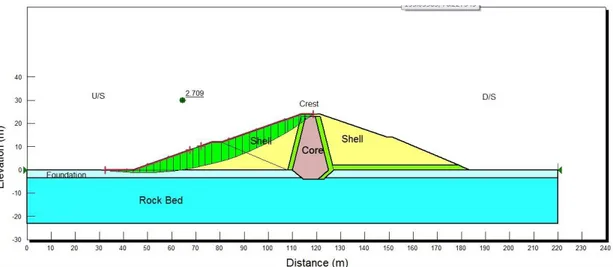
Figure 3.1. Geometry of the cross section of the Shauger Dam 34
Figure 4.1. The analysis tree for Shauger earth dam 39
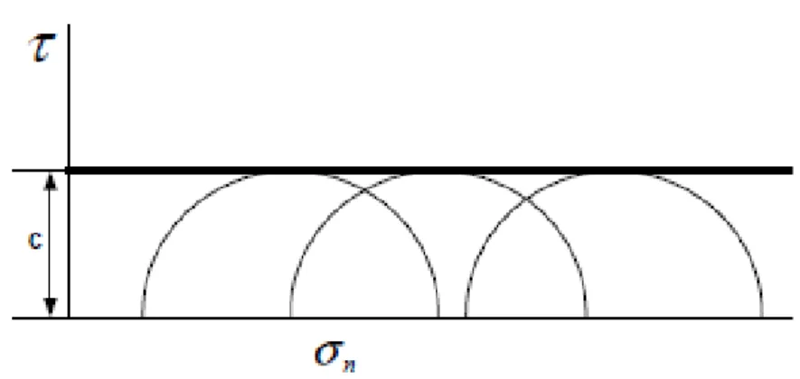
Figure 4.2. Graphical representation of Coulomb shear strength equation. 47
Figure 4.3. Mohr-Coulomb failure envelope. 48
Figure 4.4. Undrained strength envelope. 48
Figure 4.5. Free body diagram and force polygon for Bishop's method 49
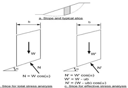
Figure 4.6. Typical slice and forces for Ordinary Method of Slices 50
Figure 5.2. Insitu pore water pressure for Shauger dam 56
Figure 5.3. Deformation for Shauger dam 5
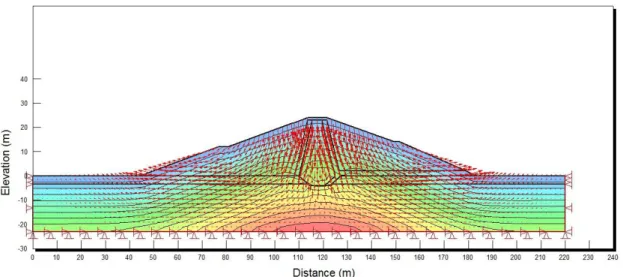
Figure 5.4. Deformation direction for Shauger dam. 5
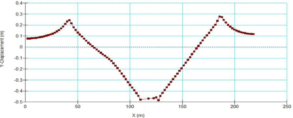
Figure 5.5. Displacements graph for Shauger dam. 5
Figure 5.6. FoS for D/S Slope Stability analysis at the end of construction 59
Figure 5.7. FoS for U/S Slope Stability analysis at the end of construction 59
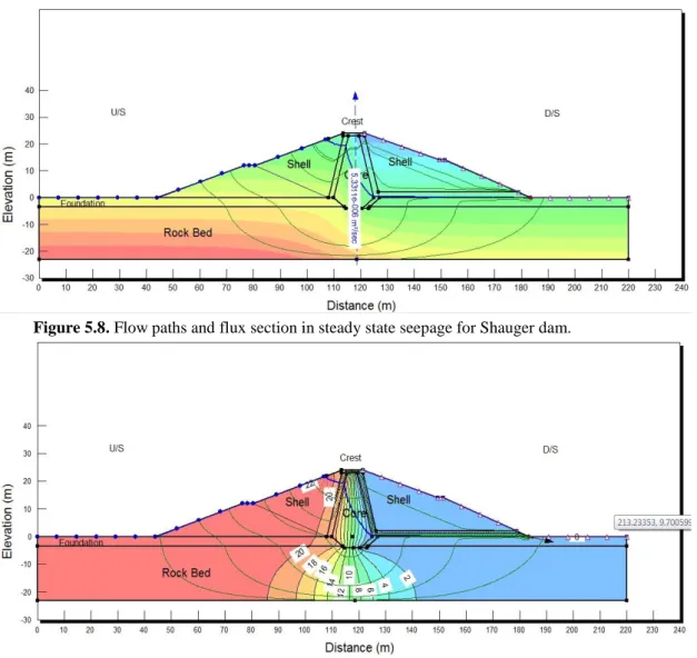
Figure 5.8. Steady state seepage flow paths and flux section for Shaugerdam 6
Figure 5.9. Steady state seepage total head for Shauger dam 6
Figure 5.10. Steady state seepage with dynamic analysis for Shauger dam 6
Figure 5.11. Steady state seepage total head graph for Shauger dam 6
Figure 5.12. Steady state seepage pressure head graph for Shauger dam 6
Figure 5.13. Steady state seepage pore water pressure graph for Shauger dam 6
Figure 5.14. Y-Gradient vs. distance at level 0m 6
Figure 5.15. X-Gradient vs. distance at level 0m 6
Figure 5.16. Y-Gradient vs. distance at level 0m 6
Figure 5.17. Slope stability D/S analysis with full reservoir for Shauger dam 6
Figure 5.18. Slope stability U/S analysis with full reservoir for Shauger dam 6
Figure 5.19. Slope stability U/S analysis with rapid drawdown 6
Figure 5.20. Slope stability U/S with earthquake dynamic analysis 6
Figure 5.21. Slope stability D/S with earthquake dynamic analysis 6
Figure 5.22. Displacement analysis with earthquake dynamic analysis 6
Figure 5.23. Y-displacement vs distance graph with dynamic analysis 6
Figure 5.24. X-displacement vs Y graph with earthquake dynamic analysis
Figure 5.25. Effective stress in case of earthquake dynamic analysis. 69
Figure 5.26 Liquefaction zone with earthquake dynamic analysis 7
Figure 5.27. PWP in case of instantaneous drawdown analysis at 7th day 7
Figure 5.31. Total head in case of slow drawdown analysis at 7th day
Figure 5.32. PWP in case of slow drawdown analysis at 7th day
Figure 5.33. Phreatic lines for all time steps in transient slow drawdown
Figure 5.34. Slope stability U/S analysis in case of slow drawdown at 6hrs
Figure 5.35. Slope stability U/S analysis in case of slow drawdown at 7th day
Figure 5.36. Minimum FoS vs. time steps in transient slow drawdown 7days 7
Figure 5.37. Phreatic lines for all time steps transient slow drawdown 30days
LIST OF TABLES
Table No Page No
Table 3.1. Shear strength parameters 32
Table 5.1. FoS results at end of construction using many methods 58
Table 5.2. FoS results for full reservoir using many methods 63
Table 5.3. FoS results for rapid drawdown using many methods 65
Table 5.4. FoS results for dynamic analysis using many methods 66
CHAPTER ONE
INTRODUCTION
1.1 INTRODUCTIONFrom earliest times, the human beings constructed the earth dams, to storewater to handle their primary needs in water supply and agricultural uses. Earth dams have been used since the earliest times; they are simple compacted structures that dependon their mass to resist sliding and overturning and are the most familiar type of dam found worldwide. The background of earth dam constructions in various forms and dimensions returns to long times ago [6] [28].
Modern machines and developments in soil mechanics have greatly increased the safety and life of earth dams. Nowadays, construction of earth dams is greatly appreciated in worldwide, so that; the number of these dams exceeds other dam types. However, the break of earth dams is considerable, comparing with other dams. Studies illustrate that the breakage due to the gradual occurrence of earth dam break, informing downstream inhabitants about the incident and sudden failure of dam as well as transferring them to safer places in upstream is quite possible [6] [28].
Dam engineering is an engineering science which enables the use of water resources as flexibly as possible, to fit the needs and schedule of humans. It could be used to draw benefit from these water resources or to give protection against threats due to sudden changes in the trend followed by these same resources. As a concept, dam engineering has been developing for thousands of years as man’s thinking abilities grew and its need to control its environment grew with it [30]. Designing and construction of an earth dam is one of the key challenging in the field of Geotechnical engineering, because of the nature of the varying foundation condition and the range of properties of the material available for construction. The major advantages of the earth dams are easily adapting to the foundation and accommodate even in difficult site condition. The most common and basic earth dams are known as homogeneous. This type of dams entirely constructed with same material. However, at present designing of earth fill dam
with relatively impervious core is increased for the purpose of controlling seepage through the dam [5].
Evaluating the stability of slopes and water seepage in soil is an important, interesting, and challenging aspect of civil engineering. However, they are a major concern when those unstable slopes and/or seepage would have an effect on the safety of dam then the safety of people and property. Over the past decades, development of new and more effective types of instrumentation to observe the behavior of dams, and use of computers to perform thorough analyses improved understanding of the principles of soil mechanics that connect soil behavior to dam stability in several critical cases such as stability of the dam slopes at the completing of the dam with and without full water level in the reservoir, rapid draw down of water in the upstream side, earthquake effect, pore water pressure and seepage through and beneath the dam [23].
If the dam break it will leads to release a huge amounts of water, that usually will be in huge waves running toward downstream areas, which causes hazardous disasters floods. Dam break usually leads to inevitable financial losses and the death tolls depend on the population of downstream. The losses may be reduced by alarming before disaster [6].
In the last decades several dams in the worldwide have failed because of inadequate dam engineering works involved. Therefore a careful attention, regular inspection and re-evaluation should be focused on earth fill dam to prevent possibilities of failure [5].
1.2 PROBLEM STATEMENT
According to the statistics, there was in every year in the last decades one or more dam failure occurred in the world. Dam failure is a disaster and makes a huge hazards, it causes damages in everything in the receptor area in downstream. Usually there are huge losses in people, properties and environment. Furthermore in the last years the climate of the region tends to oscillation. On winter 2013, there was an intense rainfall occurred in Iraqi Kurdistan Region that resulted an increase of water level more than expected level,
that is critical case. Therefore the geotechnical re-assessment of dam safety is very important issue.
1.3 OBJECTIVE OF THESIS
The purpose of this thesis is to make geotechnical re-assessment (re-evaluation) of Shauger earth dam exists in Iraqi Kurdistan Region and to find out the safety of the dam. The work includes a numerical study on earth dam safety using finite element method by using Geo-Studio 2012 computer software.
1.4 PREVIOUS WORK
The following related work review coducted to find out the previous works and previous researches on topics related to evaluate the earth dam safety. It is worthwhile to point out the following works.
In (2010) Umaru and et al. had studied structural failures of Cham earth dam in Nigeria. The study investigated the reasons of the earth dam failure. Cham dam failed in 1998 after completed in 1992. The study revealed that the failure occurred as a result of hydraulic failure (overtopping) and seepage failure (piping at downstream toe of the dam). There were faults in the design and in the construction of the dam. The freeboard amounted was only to 0.636m. The spillway was designed to have a capacity of 200m3/s, while in the field its capacity was 75 m3/s [32].
In (2010) Ambikaipahan carried out analyzing the seepage and stability of the Arbogen dam in Norway and the reliability for the extreme flood condition caused by the intense rainfall. The analyzed was done by using the GeoStodio software. The dam has been failed during an intense rainfall occurred in 2010 with three major slides along the downstream slope. The seepage and stability analysis have been done for 3 selected profiles across the embankment. Seepage analysis results for the profile 1 shows that the seepage through the embankment at normal conditions was 6.22×10⁻⁵m3/s and it is increased up to 9.89×10⁻⁵m3/s during the flood. This shows that the deposit is not well compacted.
The factor of safety for the normal dam condition was 1.076 and during the flood, it was reduced up to 0.799 from the stability analysis which shows, getting more critical stability condition [5].
In (2010) Khattab studied the slope stability factor of safety (FoS) against Mosul dam embankment sliding considering a rapid drawdown and earthquake condition by using Bishop, Morgenstern-Price and Lowe-Karafiath methods. Saturated unsaturated condition was considered assuming the shear strength parameter (Ø) to be (0, 0.5Ø, Ø). He used Geo-Slope office software for his study. Seepage analyses were done for three period rapid drawdown (8, 21, 30days). Results indicated that the critical slope stability occur during 8days drawdown. The effect of considering the unsaturated conditions was found to increase the FoS. The results of slope stability FOS during the earthquake shows a very critical FOS near and below 1.0 for all the three rapid drawdown periods (8, 21, 30days) and for all (Ø) values [18].
In (2011) AL- Gazali used a finite element model to analyze the two- dimensional steady state seepage of water through AL- Adheem Dam and its foundation. He used the computer program TDFIELD to determine the head at nodes and the hydraulic gradients. He compared between the obtained hydraulic gradient values and that recommended. He obtained that AL- Adheem dam is safe against seepage and there is no need to use any control devices for seepage (cut-off, dense core, and grout curtain) [3].
Nourani and Ghaffari (2012) in their study assessed slope stability in embankment dams using Artificial Neural Network (ANN) (case study on zonouz embankment dam). For this purpose they use two-dimension model. Feed forward back propagation with Levenberg-Marqardt algorithm was employed for training ANN. The result indicated that the base angle has more influence on safety factor than any other parameters which are (slice width, slice weight, base normal force, base shear resist force, etc) [20].
In (2013) Sachpazis studiedthe slope stability and made analysis of the original Carsington earth dam failure in the UK. In 1984, about 400m length of the embankment
and the dam maximum height was 35 m. The slope stability was analyzed by using Finite Element Analysis technique at the three loading cases: The right after construction condition, the steady seepage condition and the rapid drawdown condition. From the results, the reasons of the slope failed became obvious as follows: The minimum factor of safety forall cases was less than one (0.96, 0.81, and 0.5) which means imminent failure conditions. The mistake of the designer was that none of the assumed slip surfaces passed through the upper part of the core section at crest [10].
Figure1.1. Representative cross section of the original and reconstructed Carsington earth dam [10].
In (2013) Hasani and et al. used the Seep/W software for seepage analysis in Ilam earth dam. In order to evaluate the effect of the type and size of mesh size on the total flow rate and total head through the dam cross section, they considered four mesh size: coarse, medium, fine and unstructured mesh. Result showed that average flow rate of leakage under the different mesh size for Ilam dam equal 0.836 liters per second for the entire length of the dam. Also they used Slope/W software to analyze each slope with Bishop, Janbu, ordinary method of slides and Morgenstern methods they considered the minimum safety factor in each of these methods, as a safety factor of slope stability. They found out that the slopes are in safe side [16].
state water level and water level drawdown by using numerical finite element method analysis using Geostudio software and compared with Morgenstern-Price method. He found that the dam is in safe side according to the results of both methods. And he suggested that the finite element method is more realistic, more accurate and more promising [22].
The work in this thesis includes using finite element technique to investigate the safety of Shauger earth dam (which is located in Iraqi Kurdistan Region) against the slope stability, self stresses, seepage, and earthquake, by using Geo-Studio software.
1.5 ORGANIZATION OF THE THESIS
The entire thesis is divided into six chapters along with an appendix included at the end of the thesis.
The first chapter consists of introduction, objective of thesis, problem statement and then review of previous work. The second chapter gives a detailed background about the earth dams begins with introduction, definition, types of dams, purposes, characteristics, main parts, important studies and designs, forces acting on dams, design criteria, dams failure and assessment of dam safety. The third chapter explicitly describes the basic information for the case study dam (Shauger earth dam) and its geotechnical properties. Chapter four speaks about methodology and presents the details of the numerical and finite element analysis methods in Geo-studio software program. Chapter five consists of analysis results and discussion. The last chapter provides conclusions and the scope for further research; this chapter is followed by references and then appendix A.
CHAPTER TWO
EARTH DAMS
2.1 INTRODUCTIONLong times go when earth embankments have been used to store and control water.Earth damis a well compacted soilstructure, it depends on its huge mass to be stable against failure, earth dams are the most common kind of dams found.Modern machines and developments in soil mechanics in the recent centuries lead to increase the age and safety of earth dams [28].Nowadays earth dams are very important to integrate the infrastructure of Nations and have a significant role to manage water resources in rivers.Earth dam is a very economical solution for complicated geological sites which are vary from site to another site, because earth dams have flexibility in the design and construction more than other dam types [9].
The variation in the foundation conditions and material properties that will be used in the dam construction is making the design and construction of earth dams to be some complex. To design an earth dam, at first step hydrological, topographical and geological studies for the whole site should be done. Then the second step includes to test and fined the properties and characteristics of material that will be used to construct the earth dam. Then in the next step, based on the all previous studies the design will be begin take in consideration all technical criteria and important requirements. The next step is the construction of dam. The final step is the operation and management the dam by continuous monitoring, maintenance and periodically re-evaluation the design and the perfonmance of the earth dam [9 ][25].This chapter gives a detailed background about earth dams.
2.2 DEFINITION
Earth dams are simple structures which stand on their self-weight to prevent the sliding and overturning. These dams are the most widespread type of dams known in the world. At the earlier time the earth dams are constructed to divert massive water body and protect the community. Later it was structurally improved and used to construct the reservoirs [5].
Earth dams are the dams which are built of compacted soil or rock fragments, with a nearly trapezoidal cross section. It is an engineering structure constructed to reserve water for various purposes.
2.3 TYPES OF DAMS
In general dams can be categorized according to their main building materials into two types, concrete dams and earth dams. Earth dams can be categorized into two subtypes, soil fill dams and rock fill dams.
Soil fill dams are built from nearby soil, and had a huge body comparing with concrete dams. While rock fill dams are also has a huge body, but built from nearby rock fragments if the nearby borrow pits is rock and there is no enough amount of soil nearby [30].
The following summarize structure types of dams: 2.3.1 Gravity Dams
Keban dam on the Firat river (Figure 2.1) is an example of a gravity dam in Turkey[13].
Figure 2.1. Keban Dam [13].
2.3.2 ARCH DAMS
Arch dams transmit most of the horizontal thrust of the water behind them to the abutments by arch action and may have comparable thinner cross-sections than gravity dams. Arch dams can be used only in narrow canyons where the walls are capable of withstanding the thrust produced by the arch action [13]. Dokan Concrete Dam on the Small Zab river in Kurdistan of Iraq is an example of arch dams,see figure 2.2.
Figure 2.2. Dokan Concrete Dam.(Source: Web_1 2015)
2.3.3 BUTTRESS DAMS
Dam which has a series of supports in its face called butter dam. The face of butter dams may take forms such as curved or flat.
Figure 2.3. A buttress dam Koot dam.(Source: Web_2 2015)
2.3.4 EMBANKMENT DAMS
Embankment dams can be divided into two types as earth dams and rock dams [13].
2.3.4.1 ROCK DAMS
The main body of a rock dam have arock mass, that is supply to obtain the repose angle. By this way slope of about 36 degrees is obtained. Stability and impervious zone can be constructed by using differnt size of rock element. By using the one of material such as concrete face, asplalt, impermeable soil, concrete slash or other materials an impervious membrane can be formed. Some example of rock dam in Turkey are Hirfanlı on Kızılırmak and Hasan Uğurlu which constructed on Yeşilırmak (figure
Figure 2.4. Hasan U_urlu Dam [13].
2.3.4.2 EARTH DAMS
An earth dam is made up partly or entirely of pervious material which consists of fine particles usually clay, or a mixture of clay and silt or a mixture of clay, silt and gravel. They are principally constructed from available excavation material. The dam is built up with rather flat slopes [13]. Duhok damis an example of earth dams in Kurdistan of Iraq.Figure 2.5 shows an earth dam.
Figure 2.5. Duhok Earth dam.(Source: Web_3 2015)
In general there are two types of earth dams:
2.3.4.2.1 HOMOGENEOUS EARTH DAMS
Homogenous earth dams are mainly composed of one type of material, besides the slope protection material [13]. In homogenous there are problems of pressureand seepage. In case of seepage is excessive then it can lead to instability of the downstream face. Usually using a rock toe or gravel drainage layer as a blanket to solve the problem of seepage in the downstream where there is impervious foundation. Coarse sand and gravel shouldoverlain onrock toe to prevent embankment materials being washed into it, which could reduce the permeability of the toe. If the foundation is exist stream beds then the natural drainage layer can be worked as blanket or drainage layer. The seepage relief structure should only be beneath the downstream and not extend to upstream that could lead to direct seepage from upstream.
In general, this type usually have flat slops (1:3 U/S and 1:2 D/S) to giveslope stability. The reson of that theupstream slope is flatteris to Allow the part under water
the dam, may be than the horizontal thrust gives by the water against the embankment. The reservoir level should not rapidly dropdown or rise too fast. A rapid rise in the reservoir level may leads to erosion in the cracks and fissured parts [28]. Figure 2.6 shows a homogeneous earth dam.
Figure 2.6. A simple design of a Homogeneous earthfill dam [5]
2.3.4.2.2 ZONED EARTH DAMS
This type of This type is a good alternative especially for large dams.In zoned type damsthe seepage hazards are reduced to a minimum. The costs are higher compared with homogeneous type, Because the works are done in three zones: upstream zone which is semi impervious, core zone which is impervious and downstream which is pervious, the materials of all these three zones should be excavated from various borrow areas, thus increasing excavation and movement costs. Howeverslopescan be reduces to 1:22 for upstream and to 1:1.75 for downstream, sometimes may be 1:2.25 for upstream and 1:2 for downstream when the permeability of available materials is poor. Rock toe should be built, which is required for draining the seeped water in the downstream and the riprap(stone) facing on the upstream face is very important to protect the face from waves attack. The end of embankments and abutments and spillways need to protect from erosion by using concrete or shielded by gabions. As an alternative to clay cores, such as heavy duty plastic sheetinghave successfully used.
resist the settlement of the soil after dam construction completed [28]. Figures 2.7 and 2.8 shows a zoned earth dam.
Figure 2.7. A simple design of a Zoned earthfill dam [28]
2.4 PURPOSES OF EARTH DAMS
Earth dams are the most common type of dams known in the world. At the earlier time the earth dams are constructed to divert massive water body and protect the community. Later it was structurally improved and used to construct the reservoirs [5].
Dams are constructed to reserve water to use for various purposes. The main purposes of any dam are [13]:
For Agriculture and Irrigation. For Water supply.
For Flood protection. For Tourist purposes. For Power generation. For Navigation.
Recharging ground water.
The function of a dam may be one, many or all above purposes.
2.5 CHARACTERISTICS OF EARTH DAMS
The advantages ofconstruction of earth dams are local natural materials are used, the unit cost of compacted fill is much less as compared to concrete dams, so their total cost is usually less, they are designed as gravity dams, comparing with other types of dams earth dams needs small equipments and plants for construction, and its foundation is very simple and less requirements, it is natural foundation with few treatments, because earth dams have wide base which means spreads the load and no needs to construct a huge rigid foundation, just the natural earth almost is sufficient and resists settlement and movements. The disadvantage of earth dams are: it is easily damaged by overflow water or raining, adding adequate spillway to solve the problem of overflow [28] [33].
2.6 MAIN PARTS OF EARTH DAMS
Most dams are generally comprised of some main components. Some of the main components included are an impervious core, a drain and/or a filter, earth fill material, etc. Most dams are constructed by putting an impervious core in the middle and more permeable material on the sides and this is achieved by compacting successive layers of soil. The following principal dam sections’ functions:
Impervious core which is provided for the purpose of keeping the retained material on the upstream side by controlling seepage through the dam.
Drain the seeped water through the dam should collect and drained out to reduce uplift pressure, erosion and piping [9]. Controls erosion of core material and dam foundation by seepage water by being used as a horizontal drain in the latter case. When used as a vertical drain, it also controls buildup of pore pressure in the downstream face. Filter which will prevent particle migration/erosion of the core material due to
excessive seepage forces into the fill material or through the rip rap.
Fill material(shell) for giving the whole structure weight for stability against an immense destabilizing force from the retained material and it is usually free draining to allow passage of seepage under and through the dam [30].
Cutoff trench and core(diaphragm)Cutoff is very important for the earth dams it increases the stability of the dam and reduces the seepage because usually clay material is used. Cutoff trench should be excavating until reaching a good foundation or rock layer. In case of underlying rock bed beneath the trench is fissured then usually grouting with thick slurry and cement mixture should be used [28].
The spillwayIt is very important part for earth dams and should be carefully designed to be adequate for the dam in case of peak flood. Spillway should be carefully constructed and protected by concrete to prevent erosion [28].
Discharge (Outlet works and conduits)It is used for releasing water to downstream regularly and to control the reservoir level to be within required levels according to the regulation requirements. It should has capacity to discharge 90% of the storage within 14 days supposing no inflow. It should has
gate or valves to control the discharge. Outlet conduits should have capacity to resist the loads of embankment and water [21].
2.7 IMPORTANT STUDIES AND DESIGNS FOR THE EARTH DAMS
The following main studies should be done to design an earth dam satisfies the engineering requirements and specifications [31]:
Geological studies: geological survey should be achieved for the site, it includes the tectonic and earthquake studies for the Stratigraphy stratification formation, magma formation, faults if there is and etc. of the dam site and reservoir area, to find out that the location is suitable or not for dam construction from geological point of view.
Hydrological studies: collecting all the weather and climate reports data from meteorological stations near the site of the concerned area for all previous years, to analyze the data and find out the maximum amounts of rainfall and runoff for the catchment area and the river discharge.
Topographical studies: This study aimed to invest (exploitation) abilities of the earth surface of the dam site and the reservoir area.
Geotechnical studies: it includes in-situexploration and taking samples for laboratory tests to find out the geotechnical properties of the site earth materials, and designing the dam body and its all accessories depending on the above mentioned studies information.
2.8 FORCES ACTING ON DAMS
2.8.1. WATER PRESSURE
Water pressure acts perpendicular to the surface of the dam (see figure 2.9) and is calculated per unit width as follows:
Figure: 2.9. Illustration sketch for hydrostatic water pressure.
………...…….………..2.1 Where γw is the specific weight of water and h is the height of water.
Dams are subjected also to uplift force (U) under its base. Uplift acts upward see figure 2.10.
Figure. 2.10: Illustration sketch for uplift pressure.
...………..2.2 Where B is the width of the base of the dam.
Water has additional force it is internal pore pressure effects the dam besides the external pressures. 2 2 1 h P w hB U w 2 1
2.8.2. WEIGHT OF DAM
The weight of the dam itself is another force that acts on dam structures. The weight of the dam is calculated as follows:
...……….2.3 Where γm is the specific weight of the dam’s material.
2.8.3. EARTHQUAKE FORCES
Dams are subjected to vibration during earthquakes. Vibration affects both the body of the dam and the water in the reservoir behind the dam. Vibration forces are function of both the intensity of the earthquake (Rechter Scale) and its duration. The most danger effect occurs when the vibration is perpendicular to the face of the dam.
The earthquake exerts horizontal force and the level of this force is about ten percent of total weight of Dam [13].Body force acts horizontally at the center of gravity see figure 2.11 and is calculated as:
Figure: 2.11. Illustration sketch for earthquake forces.
…...……….………..2.4
Where α (Is taken 0.2 for practical reasons) is the earthquake coefficient and W is the weight of the dam.
xVolume W m
W Pem
Water vibration produces a force on the dam acting horizontally, see figure 2.12.
Figure: 2.12. Illustration sketch for Water vibration forces.
………..………...………2.5 Where Ce is another coefficient (0.82) and h is the height of the water.
2.8.4. ICE AND WAVES FORCES
A thichk layer of ice can be formed on reservoir surface in cold climates. Due to expansion of ice sheet a big amount of force can ocur about top of the dam. Therefore this part of the dam should be constructed in enough tickness to bear the pressure. The upper part of the dam (above the water level) is subjected to the impact of water waves. The maximum wave pressure per unit width is:
………...………2.6 Where hw is the wave height which depends on reservoir length and the wind
speed.
2.9 EARTH DAM DESIGN CRITERIA
An earthfill dam should be designed with relatively flat slopes to reduce the possibility of failure. The design is unique for each earthfill dams because of the location of the dam and the variety of materials to be used for construction. Purpose of the dam also plays an important role on design criteria. The factors mentioned above bring hard to define general design criteria. However, every design criteria must be included the following fundamental design aspects [5]:
v w v h P 2.4 2 3 2 h C Pew e
Stability of embankment and foundation in critical conditions such as Earthquake and flood.
Control of seepage and pressure in both embankment and foundation. Safety measures to control overtopping situation.
Erosion control methods.
A dam may lose its performance by time because of the long term changes in the properties of constructed materials. To maintain the performance of a dam, critical conditions such as earthquake, overtopping and unexpectable increase of seepage quantity are should be overcome with controlling structures such as filter – protected chimney drains, horizontal drain blankets, foundation cut – offs, relief wells and abutment drainage curtains [5].
2.10 DAMS FAILURE
The failure is happen due to uncontrolled and unintended seepage of storage water, or an event whereby a dam is rendered unfit to safely retain water because of a total loss of structural integrity [4].
2.10.1 MODE OF FAILURE
The mechanism that the hazards occurs failure is named as mode of failure. In following some of important mode of failure were presented. [4] [34].
2.10.1.1 OVERTOPPINGUncontrolled flow over the dam crest. Figure 2.13 illustrates this case.
2.10.1.2 DAM BREACH
Uncontrolled flow of water though the dam’s main structure, which includes its foundation. Figure 2.14 shows dam breach case.
Figure 2.14. dam breach case.(Source: Web_5 2015)
2.10.1.3 FOUNDATION FAILURE OF EMBANKMENT DAM
When the design loads are greater than the bearing capacity of foundation the ultimate failure of foundation of dam occurs. Figure 2.15 foundation failure type of embankmentwere presented.
2.10.1.4 INSTABILITY OF EMBANKMENT DAM
One or more slips occur within the embankment because design loads are exceeded or through a reduction in shear strength of embankment-fill materials over time.
2.10.1.5 OVERFLOW FAILURE DUE TO SPILLWAY DAMAGE
Overflow or spillway is unable to contain flow during flooding and uncontrolled flow results. Structural failure may occur. Figure 2.16 shows a spillway damage example.
2.10.1.6 STRUCTURAL FAILURE OF EMBANKMENT DAM
An increase in permeability and/or reduction in strength of core occurs over time, and results in ultimate failure of the embankment dam structure. Muddy discharge downstream of dam as a result of increased seepage and internal erosion is an indication of this case.
2.10.1.7 STRUCTURAL FAILURE OF EMBANKMENT DAM (LOAD EXCEEDED)
Ultimate failure of embankment dam structure occurs because of design loads are exceeded and/or through deterioration of embankment-fill materials over time. Figure 2.17 illustrates this case.
2.10.1.8 UNCONTROLLED FLOW BECAUSE OF APPURTENANT WORKS FAILURE
Structural failure of one or more appurtenant works occurs because of a change in load conditions or deterioration of works over time that results in the uncontrolled release of water.
2.10.1.9 UNCONTROLLED SEEPAGE
Uncontrolled passage of water through, underneath or around a dam. 2.10.2 REASONS OF DAM FAILURE
The following threats are some reasons of failure events [4]: • ageing
• aircraft strike • animal activity
• changes in groundwater flow/chemistry • earthquake
• extreme rainfall/snow flood • failure of nearby infrastructure
• failure of reservoir in cascade upstream • human activity
• ice/frost
• terrorism/sabotage/accident • wind
The threats listed above may lead to development of one or more following damages which cause dam failure [4]:
Differential settlement or deformation
Rapid drawdown Lowering the water level in a reservoir faster than the pore pressures can dissipate from the upstream shoulder of an embankment dam. Reduced freeboard due to settlement or internal erosion.
Seepage can cause internal erosion. Concentrated erosion
Backward erosion (piping)
Internal erosion along an appurtenant structure Animal activity by create burrows, holes, tracks etc.
High pore-water pressures lead to increased seepage, hydraulic fracture or instability.
Blockage of spillway
Inadequate energy dissipation at the end of a spillway. Out-of-channel flow in spillway.
Overflow capacity exceeded insufficient hydraulic capacity. Deterioration of core or foundation or upstream face. Cut-off deterioration.
Blocked drains and relief wells no longer carry out their design function to control uplift pressure.
Blocked screens reduces flow capacity. Failure of controls, valves or gates.
Local run-off on the upstream or downstream side this can cause local erosion. Wave attack due to wind or external effect.
Researches indicate that the main factors in dam breaks are as follows: Overflowing due to low capacity of water discharger (34%), foundation defects (30%) and piping and seepage (26%) [6].
2.10.3 HAZARDS DUE TO DAM FAILURE
If the dam break it will leads to release a huge amounts of water, that usually will be in huge waves running toward downstream areas, which causes hazardous disasters floods. Dam break usually leads to inevitable financial losses and the death tolls depend on the population of downstream. The losses may be reduced by alarming before disaster [6].According to the statistics, in every year in the last decades there is one or more dam failure occurred in the world. Dam failure is a disaster and makes a huge risks, it causes damages in everything in the downstream. The following are some of losses:
• Human victims (killing, injuring).
• Dam failure means lose the dam itself, its benefits and purposes. • Destroys Roads bridges, airports and cars.
• Destroys houses, buildings, warehouse, power plants and factories. • Destroys agricultural lands, and projects.
• Destroys power lines and water irrigation and drainage channels. • Losses in goods, furniture and etc.
• Indirect losses such as: diseases, pollution, the need to remove the damage things and flood remains.
All above losses mean too financial losses in billions. Therefore the assessment of dam safety is very important issue.
2.11 ASSESSMENT OF DAM SAFETY
The earth dam location, height, long, capacity, etc. determine after completing the topographical, hydrological, geophysics and geological studies. Then geotechnical studies will begin to design the earth dam body from the available nearby borrow materials. The safety assessment of an existed dam includes geotechnical, hydrological, ageing, etc. assessments. Geotechnical assessment involves checking the dam safety against the slope stability analysis in all critical conditions, seepage analysis, and self weight stresses, these analyses usually done by using new professional computer software, like Geo-Studio or/and Plaxis computer programs.
CHAPTER THREE
SHAUGER EARTH DAM
3.1. PREFACE
This chapter includes basic geotechnical information about Shauger earth dam. This information collected from directory of dams in Erbil.Shauger earth dam selected for this study due to the availability of extensive geotechnical data for the analysis and that this dam is a good represented sample for many earth dams constructed or under construction in the Iraqi Kurdistan Region.
3.2. INTRODUCTION
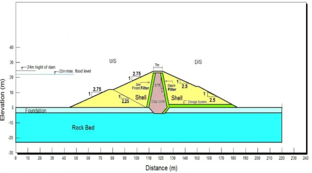
The Shauger earth dam is located in Iraqi Kurdistan Region, it is about 24 meter height its crest crown is designed to be at 506.2 m.a.s.l level at the highest sections its width is 7 meter. At the crown the crest slopes 2% to both upstream and downstream directions. The crest of the dam is designed to carry normal car vehicle traffic. The upstream face of the dam has a slope of 1:2.75. The downstream slope of the dam designed to have a 1:2.5 slope with 2 meter berm. The upstream slope is covered with a hand placed riprap of 40 cm thickness, A bedding material of 20 cm thickness underlie the rock fragments of riprap, it consists smaller fragments of stones and cobbles. The downstream slope is covered by coarse gravel and fine cobbles of 40cm thickness to protect the slope from erosion. A surface drainage canals is provided at the contact areas of the dam with the abutments and natural ground to drain the rain water at the lowest level at the downstream to prevent erosion at this area. A cofferdam which its crest is at 494 m.a.s.l. level with 4m width is a part of the main dam body and its crest will be a berm for the upstream slope. The upstream face of the cofferdam has a slope of 1:2.75, while the downstream slope of the cofferdam designed to have a 1:2.25 slope.
3.3. CORE SEAL MATERIAL
The dam consists of a seal core of clayey silt soil it is classified as (CL) according to unified soil classification system. The crest of the core is at 505m.a.s.l level and its width at the core crest is 4 meter it expanded with a slope 1:3.75 to the direction of the foundation to reach about 15 meter at lowest level of the dam. Core material is extended to different depths into the alluvium deposit at the different locations to act as a sealing cut off. It reach the bed rock and it extracts it at least 0.75 meters. The dry density for the core is 1.95 gr/cm3.
3.4. SHELL MATERIAL
Shell material classified as poorly graded gravel; it compacted to a relative density not less than 85 % or 95% degree of compaction of modified compaction test.The dry density for the shell is 2.0 gr/cm3.
3.5. FILTER MATERIAL
The filter material that provides both permeability and piping criteria sandwiches the core slopes from both upstream and downstream sides it has a 1.8 m thickness. The filter material is designed with two layers each of 90cms. The filter layer attached to the core is designated filter 1 it comprises from sand material. The filter layer attached to the shell material side is designated filter 2 it comprises gravel material. A blanket filter with same sand and gravel material each of 100cm thickness is provided at the downstream of the dam.
3.6. EARTHQUAKE
Shauger dam site is located at zone 2.0 indicating kh value of 0.2 , which is used
in the stability analysis. The earthquake effects has been considered by introducing the horizontal acceleration coefficient kh equal to 0.20 .
3.7. PERMEABILITY
The values of coefficient of permeability are as follows: Shell material k(cm/sec) = 1x10⁻⁴
Core and cutoff material k(cm/sec) = 3x10⁻⁷
Foundation material Quaternary k(cm/sec) = 2.5x10⁻⁵ Rock bed (claystone) k(cm/sec) = 5x10⁻⁶
3.8. SHEAR STRENGTH PARAMETERS
The values of Shear strength parameters are as follows: Table 3.1. Shear strength parameters.
Core of dam Shell Filter Bed
Rock Quaternary C (kPa) υ (deg.) C (kPa) υ (deg.) C (kPa) υ (deg.) C (kPa) υ (deg.) C (kPa) During construction and End of construction 150 0 20 35 0 33 4000 35 0 Steady state seepage under active conservation pool 70 11 20 35 0 33 4000 35 0 Steady state seepage with earthquake 70 11 20 35 0 33 4000 35 0 Sudden draw down 70 11 20 35 0 33 4000 35 0
3.9. SUMMARY
The basic information about Shauger earth dam is given below: 1-Type of Dam: (Earth Dam)
2-Height of Dam: 24 m
3- Stream Bed level : (483) m.a.s.l
4-Width of the valley at the Dam site: (40) m 5-Crest width: (7) m
6-Length of the Dam (at the crest level): (93.5) m 7-Max flood level: (504) m
8-Max dam operation level: (502.5) m 9-Max capacity: (1,083,023) m3 10-Dead storage : (273849) m3 11-Reservoir area: (0.120783) Km2 12-Catchment area : (20) km2 13-Spillway : (65) m3/Sec
3.10. GEOMETRY OF SHAUGER EARTH DAM PROFILE
The general geometry and the foundation layers of the Shauger earth dam profile is shown in figure 3.1. It should be noted that this profile is not to scale.
CHAPTER FOUR
METHODOLOGY
4.1 INTRODUCTIONThis chapter presents the details of the numerical analysis and finite element analysis. It includes the description of the constitutive model, type of mesh, and conditions employed in the study by using Geostudio program to re-evaluate Shauger earth dam from geotechnical view.
Experience has important role in the design of earth dams. The detailed analysis is needed to understanding the sensitivity against material properties. To validate the experience and judgment of the designers comparisons of actual versus predicted failure modes of a dam should be done.
Evaluating the performance of earth dams is paramount to assuring their safety and continued operation. Thorough and timely judgment of engineers with the knowledge of case specific characteristics of the structure is necessary for an effective evaluation.It is strongly recommended to use computer software to analyze the stability of the slopes where the conditions of analyze are complex, especially where significant data are available. Software has ability to analyze a wide variety of load conditions and slope geometry [9] [25].
4.2 NUMERICAL ANALYSIS
The mathematical simulation of a real case is called numericalmodel. There are a wide difference between numericalmodeling and laboratory modeling (physical modeling). The numericalmodeling advantages over the laboratory modeling are:
• Can be constructed minutes, hours while laboratory modeling construction may take months.
• Numericalmodeling can be used to check wide different set of conditions, while laboratory modeling can be applied for a limit conditions.
• In laboratory models gravity cannot scaled, while there is no problem for accounting gravity in numericalmodels.
• Laboratory modeling usually deals with heavy equipments and there is a danger of personal harms, while there are no dangers with numericalmodeling.
• Laboratory models give results only at discrete instrumented points and external visual points, while numericalmodels can give results at any section inside or outside the model.
• Laboratory models has limitations in accommodate the boundary conditions, while numericalmodels can accommodate wide range of possible boundary conditions.
But it should be aware that numerical models has its limitations associated with changes in temperature, volume, chemical and seepage, it cannot include all these changes in one formula because mathematically this is very complex and cannot join all these changes mathematically in relationship, because of its complexity. May the engineers in the future overcome this problem [29].
4.3 FINITE ELEMENT METHOD
The finite element method was first introduced to geotechnical engineers in 1966 Berkeley conference on stability of slopes and embankments by Clough and Woodward (1967). Unlike the limit equilibrium method, the finite element method considers linear and non-linear stress – strain behavior of the soil in calculating the shear stress for the analysis. In a finite element approach the slope failure occurs through zones which cannot resist the shear stresses applied. Hence, the results obtained from this analysis are considered to be more realistic compared to traditional limit equilibrium method [19] [25]. Finite element methods are well known for the estimating the realistic deformations of the slopes and changes in seepage amount and pore water pressure etc. in embankments due to various critical conditions. Some of the advantages of using a finite element analysis are,
1) The movement of the slopes at a particular location can be calculated. This helps in monitoring the movement of the slope. Also, soil stresses and pore water pressure responses to different external factors such as load, water level, reservoir level etc. can be calculated.
2) Stability of the slope during staged construction such as step by step excavation or construction of embankments, levees etc. can be calculated by performing incremental analysis.
3) Seepage amounts in various cases.
4) Pore water pressure, total head and pressure head amounts. 5) Earthquake forces, displacements and other effects.
A numerical method can be used to obtain an approximate solution when an analytical solution cannot be developed. Especially, the finite element method has been one of the major numerical solution techniques. One of the major advantages of the finite element method is that a general purpose computer program can be developed easily to analyze various kinds of problems. In particular, any complex shape of problem domain with prescribed conditions can be handled with ease using the finite element method [2].
The types of soil stress-strain relationships that can be used are linear elastic, elastoplastic, hyperbolic, Modified Cam Clay, elastoviscoplastic and multilinear elastic models. The selection of a particular stress-strain relationship depends on the state of the soil structure to be analyzed, its purpose of analysis and its laboratory and field properties available. The determination of soil properties in the field involves a large amount of uncertainty and so the application of finite element analyses imposes complexity on the stability problem [19] [24].
An approach to solve a slope stability problem by finite element method is to compute finite element stresses of the geotechnical structure and to implement them inside a limit equilibrium frame work to analyze its stability. It is known as finite element stress-based approach (SLOPE/W). So, the distribution of stresses in the
ground is calculated by finite element analysis and then these stresses are used in a stability analysis. For the present case study involved in this thesis, this approach is followed. The software SIGMA/W is used for calculating the insitu stresses in the landslide and SLOPE/W is used for the slope stability analysis using the stresses calculated by SIGMA/W (SLOPE/W) [19]. QUAKE/W is used for calculating the earthquake stresses in the dam and it effect on the slope stability. SEEP/W is used for calculating the seepage amounts pore water pressure, total head, head pressure, etc in the Shauger dam.
4.4 FINITE ELEMENT MODEL
The cross section of the dam profile is shown in figure 3.1. Profile a section was chosen for finite element analyses (FEA) in Geostudio program. The mesh pattern used was Quad&Triangles elements quadrilateral four node and triangular three nodes with approximately element size 1m. Geostudio program automatically generates the mesh of geometry according to the given element size. The total mesh elements were 7127 elements and the total mesh nodes were 7305 nodes. The material models used for the analyses are available in the Geostudio program materials library, which were Mohr-Coulomb for stability analysis, Saturated only for steady state seepage analysis and Saturated/Unsaturated for transient drawdown analysis. The major difference between water flow in saturated and unsaturated soil are that the coefficient of permeability is not constant but is a function of degree of saturation or metric suction in unsaturated soils and the volumetric water content of unsaturated soil can be vary with time [18]. The basic data (c, υ, γ and k) for all materials entered in the model and material well defined. Besides, boundary condition for each case defined, to use and simulate multiple scenarios for analysis, by changing the boundary conditions and material properties for the same geometry for the numerical model.
Then the model has been implemented numerically in Geostudio for multiple cases and results reported out. The analysis tree for Shauger earth dam is shown in figure 4.1.
Figure 4.1. Analysis tree for Shauger earth dam.
More details can be found in the appendix A in the report of Shauger earth dam analysis.
4.5 CRITICAL LOADING CONDITIONS
The Shauger earth Dam and its foundation was analysed against failure. Consideration of loading conditions which may result to instability must be made for all likely combinations of reservoir levels after construction. Four construction and / or loading conditions were examined in particular [11] [25]:
a.
At the end of construction conditionThe critical condition to be analyzed is at the completion of earth dam construction but prior to filling with water. In this case the water table present at the river bed level.
b.
At the full reservoir conditionFor Shauger zoned type dam when the reservoir is full of water and some steady seepage into the embankment is established, the conditions to be considered for the
steady state seepage analysis should be steady state seepage pore pressures which are fully developed as a result of the reservoir have being storing water over a long period of time. In this case there is a Phreatic Surface Line under steady seepage state.
c.
The Rapid Drawdown Condition in the reservoirRapid drawdown in reservoir water level may cause the upstream face stability to become critical mainly due to the removal of the supporting water. When the reservoir is rapidly evacuated and drawn down, pore water pressures in the dam body are reduced in two ways. There is a slower dissipation of pore pressure due to drainage and there is an immediate elastic effect due to the removal of the total or partial water load. The exact mechanism of this phenomenon is as follows: It is assumed that the reservoir has been maintained at a high level for a sufficiently long time so that the fill material of the dam is fully saturated and steady seepage established. If the reservoir is drawn down at this stage, the direction of flow is reversed, causing instability in the upstream slope of the earth dam. The “instantaneous” drawdown is a hypothetical condition that is assumed. The most critical condition of sudden drawdown means that while the water pressure acting on the upstream slope at “full reservoir” condition is removed, there is no appreciable change in the water content of the saturated soil within the embankment. The saturated weight of the slope produces the shearing stresses while the shearing resistance is decreased considerably because of the development of the pore water pressures which do not dissipate rapidly [10]. Therefore, it was considered very important such an analysis to be carried out and included in this research.
A more accurate way of analyzing drawdown is to use the seepage analysis results. This more advanced approach uses the exact pore-water pressures that were in the soil during the transient drawdown process. Using the pore-water pressure estimated from seepage analysis, the factor of safety of the earth dam at different times during drawdown process can be evaluated [26].
d.
Earthquake conditionEarthquake may cause many changes in the internal and external conditions, usually earthquake shaking apply additional lateral quake force. The response and behavior of
![Figure 2.16. Flood event of June 2005 that resulted spillway damage at Boltby reservoir [4]](https://thumb-eu.123doks.com/thumbv2/9libnet/3346148.11437/41.892.136.674.508.908/figure-flood-event-resulted-spillway-damage-boltby-reservoir.webp)
![Figure 4.5. Free body diagram and force polygon for Bishop's method[2].](https://thumb-eu.123doks.com/thumbv2/9libnet/3346148.11437/66.892.171.763.746.1004/figure-free-body-diagram-force-polygon-bishop-method.webp)
![Figure 4.8. Free body diagram and force polygon for the Janbu method[27] .](https://thumb-eu.123doks.com/thumbv2/9libnet/3346148.11437/71.892.106.647.663.1008/figure-free-body-diagram-force-polygon-janbu-method.webp)