φ ί ϊ
• X S 5
- Í S Í ¡
ІЦ-W й ¿ J ІІ iLtyÜ І«ц/ t ; ') г 'Г і (^Г / Τ*»Γ· ■' ■' ·! t .· ’ Í . J-!'.; : / <>; J ; fe.· 4-j а ¿ і JÍ ZKCLÜS32IHC· sciBMí
SIMLIB:
A CLASS L IB R A R Y FO R
O B JE C T -O R IE N T E D SIM U L A T IO N
A THESIS
SUBMITTED TO THE DEPARTMENT OF COMPUTER
ENGINEERING AND INFORMATION SCIENCE
AND THE INSTITUTE OF ENGINEERING AND SCIENCE
OF BILKENT UNIVERSITY
IN PARTIAL FULFILLMENT OF THE REQUIREMENTS
FOR THE DEGREE OF
MASTER OF SCIENCE
By
Oğuz Işıklı
July, 1993
^ ♦ bl|
■1Z‘S
0 Copyright 1993
by
in
I certify that I have read tliis thesis and that in my opinion it is fully adequate, in scope and in quality, as a thesis for the degree of Master of Science.
Assoc. Prof. Varol Akman (Co-advisor)
I certify that I have read this thesis and that in my opinion it is fully adequate, in scope and in quality, as a thesis for the degree of Mcister of Science.
Prof. Akif Eyler (Co-advisor)
I certify that I have read this thesis and that in my opinion it is fully adequate, in scope and in quality, as a thesis for the degree of Master of Science.
Asst. Prof. Özgür Uluai^
Approved for the Institute of Engineering and Science:
Prof. Mehmet
ABSTRACT
SIMLIB:
A CLASS LIBRARY FOR
OBJECT-ORIENTED SIMULATION
Oğuz Işıklı
M.S. in Computer Engineering and Information Science
Advisors: Assoc. Prof. Varol Akman and Prof. Akif Eyler
July, 1993
Simulation is one of the most widely used techniques in decision making. Math ematical modeling of a real world system is a major task of the simulation analyst. The selection of a computer language for implementing the model is also important. Recent research in this area has focused on the compatibility between simulation implementations and the object-oriented paradigm. It is the purpose of this thesis to explore the use of an object-oriented approach for the implementation of discrete event simulation applications. We present a class library which provides the skeletal elements of a simulation. The ad vantages and the disadvantages of the approach are discussed with the help of three prototype implementations: the single-queue/single-server system, the production-line system, and the elevator system.
Keywords: Discrete Event Simulation, Object-Oriented Programming, Object- Oriented Design, Class Libraries, C-|—I- Programming Language, Single-Queue/ Single-Server Systems, Production-Line Systems, Elevator Systems.
ÖZET
SIMLIB:
NESNEYE-YÖNELİK BENZETİM İÇİN
BİR SINIF KÜTÜPHANESİ
Oğuz Işıklı
Bilgisayar ve Enformatik Mühendisliği, Yüksek Lisans
Danışmanlar: Doç. Dr. Varol Akman ve Prof. Dr. Akif Eyler
Temmuz 1993
Benzetim, karar verme sistemlerinde çok yaygın şekilde kullanılan teknikler den biridir. Bir gerçel dünya sisteminin matematiksel olarak modellenmesi, benzetim analistinin temel bir görevidir. Model gerçekleştiriminde hangi bil gisayar programlama dilinin kullanılacağı da önemli bir konudur. Bu alan daki son araştırmalar, benzetim uygulamaları ile nesneye yönelik program lama arasındaki yakın benzerlikler üzerinde yoğunlaşmıştır. Bu tezin amacı, kesikli-olay benzetim uygulamalarında nesneye yönelik yaklaşımın kullanımını araştırmaktır. Tezde, bir benzetim programının temel bileşenlerini sağlayan bir sınıf kütüphanesi tanıtılmaktadır. Yaklaşımın avantaj ve dezavantajları üç prototip uygulamanın yardımıyla tartışılmaktadır: tek-kuyruk/tek-işgören sistemi, üretim-hattı sistemi ve asansör sistemi.
Anahtar Sözcükler: Kesikli-Olay Benzetimi, Nesneye-Yönelik Programlama, Nesneye-Yönelik Tasarım, Sınıf Kütüphaneleri, C-b-h Programlama Dili, Tek- Kuyruk/Tek-Işgören Sistemleri, Üretim-Hattı Sistemleri, Asansör Sistemleri.
VI
ACKNOWLEDGMENTS
I would like to thank my co-advisors Assoc. Prof. Varol Akman and Prof. Akif Eyler (Department of Industrial Engineering) who have provided a pleasant research environment and motivating support during this study.
I would also like to thank Prof. Mehmet Baray and the rest of the faculty of the Department of Computer Engineering and Information Science for the academic environment they have created.
Finally, I would like to thank my family, my friends, and everybody who has in some way contributed to this study by lending moral support.
Contents
1 Introduction 1
2 Object-oriented simulation 4
2.1 The object-oriented p a ra d ig m ... 4
2.2 Basic concepts of computer s im u la tio n ... 6
2.3 OOP and simulation code developm ent... 9
2.4 The use of a class lib ra ry ... 11
2.5 Previous and related w o r k ... 12
3 Design of the class library 15 3.1 Object-oriented design of classes... 15
3.1.1 The use of prototypes ... 16
3.1.2 Class definitions... 18
3.2 General form of a simulation a p p lic a tio n ... 20
3.2.1 Construction of a m o d e l ... 20
3.2.2 Running the m o d e l... 24
3.3 Scheduling and execution of e v e n t s ... 27
3.4 Mapping a model to a p r o g r a m ... 30
4 Implementation 32 4.1 Definition of classes... 32
4.1.1 The Sim Object c l a s s ... 33
4.1.2 The Node class...34
4.1.3 The Co l l e c t io n class... 35
4.1.4 The Queue c la s s ... 36
4.1.5 The Buffer class ... 37
4.1.6 The So u r c e class ... 37 4.1.7 The Sink c l a s s ... 38 4.1.8 The Se r v e r class... 39 4.1.9 The Ca r r ie r c la s s ... 40 4.1.10 The En t it y class... 41 4.1.11 The Distribution c la ss... 42 4.1.12 The SIMULATION c la s s ... 43 4.1.13 The SimEv e n t c la s s ... 44
4.1.14 The StableEvent class... 44
4.1.15 The Mo v in gEv e n t c l a s s ... 46
4.1.16 The Ev e n tList c l a s s ... 47
4.2 Communication between o b je c ts... 47
4.3 User-defined behavior... 51
4.4 System s e rv ic e s ... 5g
5 Three example systems 59
5.1 The single-queue/single-server e x a m p le ... 59 5.2 The production-line ex am p le... 61 5.3 The elevator ex am p le... 53
6 Conclusion 7 j
A Class declarations in SIMLIB 75
List o f Figures
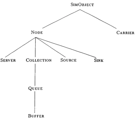
3.1 The hierarchy of system classes in S IM L IB ... 20
3.2 The definition of SERVER... 22
3.3 Constructor of Se r v e r object for the no-crash c a s e ... 23
3.4 Constructor of Se r v e r object for the cr«ish c a s e ... 23
3.5 Object declarations of the single-queue/single-server application 24 3.6 Object links for the single-queue/single-server application . . . . 24
3.7 The definition of SIMULATION... 25
3.8 An example ShouldStop m e th o d ... 26
3.9 Sample output from the method D o n e ... 27
3.10 Class definitions for the event clcisses... 28
3.11 A sample Ezecwie m e t h o d ... 30
3.12 The main body for a derived SIMULATION o b j e c t ...31
4.1 Execute method of En t i t yIn t oSy s t e m... 49
4.2 Execute method of EntityIntoQueue ... 50
4.3 Execute method of En t i t yFr o mQu e u e... 50
4.4 Execute method of En t i t yIn t oSe r v i c e... 51
4.5 Execute method of EntityFromSe r v i c e... 52
4.6 Execute method of EntityFromSystem ... 52
4.7 A subsystem with a decision n o d e ... 53
4.8 A possible definition for De c is io nNo d e... 54
4.9 Method definitions for De c is io nNo d e... 55
4.10 Method definitions for event class EntityForDecision . . . . 56
5.1 The single-queue/single-server m o d e l... 60
5.2 The code of the single-queue/single-server e x a m p le ... 62
5.3 The production-line model with two s e r v e r s ... 63
5.4 The code of the production-line e x a m p le ... 64
5.5 Model of the elevator sy stem ... 66
5.6 The Execute method of El e vEn dSe r v i c e... 69
5.7 The Execute method of Ne wEn t i t yToELEVATOR... 70
List of Tables
3.1 System classes in S I M L I B ... 19
3.2 Auxiliary classes in S IM L IB ... 19
3.3 List of event classes provided in S IM L IB ... 29
4.1 Return conditions for CanSend and C anReceive... 48
6.1 Comparison of code length (number of lines) of the three proto types implemented with and without S IM L IB ... 72
C h a p te r 1
Introduction
Simulation is one of the most widely used techniques in decision making. Math ematical modeling of a real world system is a major task of the simulation analyst. The selection of a computer language for implementing the model is also important.
Recent research in this area has focused on the compatibility between sim ulation implementations and the object-oriented paradigm [6]. The basic idea is to model the components of a system as objects and to define the behavior of the components as methods attached to these objects. Objects are treated as “black boxes,” encapsulating code and data. They communicate with the outer world through methods. This enables the representation of any system component in a modular fashion (with the advantages of readability and main tainability).
Once a clear design of the classes involved in the model is at hand, it takes less time to map the system to be simulated to a program in an object-oriented programming (OOP) language. The inheritance mechanism of OOP aids in the development of new classes from existing ones, thus resulting in reusable code. The encapsulation principle of OOP, combined with the use of abstract data types, enhances modularity.
It is the purpose of this thesis to explore the use of an object-oriented ap proach for the implementation of discrete event simulation applications. The
CHAPTER 1. INTRODUCTION
domain of interest (arguably) covers only a small portion of the simulation ap plications that are developed in the “real world,” but this is adequate to present the main idea of this study. The general structure which best illustrates our interest is a production-line model employing components like queues, servers, carriers, etc. connected to each other in a linear fashion. The execution of the model can be basically stated as the traveling of entities between components to receive service.
The general components of such a system can be modeled as objects and collected in a library for future use. While the components of the library provide the basic characteristics, it is the task of the programmer to define additional behavior depending on the particular application to be developed.
In our research, we tried to extract a minimal (in some sense, canonical) set of system components to include in our simulation library—SIMLIB. There fore, we first developed three prototype applications which may be regarded as “classical” in the area of discrete event simulation. These are (i) a single- queue/single-server system, (ii) a production-line system, and (iii) an elevator system. Our aim was to investigate the general concepts of simulation program ming along with the most frequently used data structures. Essential insights resulting from this phase of the study facilitated the design of SIMLIB to a great extent.
Later, the same systems were implemented by the classes and routines provided by SIMLIB. Using our previous experience, a comparison between the two development strategies was carried out. Major aspects of the latter approach, such as the class hierarchy, the execution of events, the navigation of entities, and the integration of user-defined behavior into system behavior, were distinguished.
SIMLIB has been implemented using the C-1--1- language [24] on SUN Work stations^ running under the UNIX^ system. C-1-+, inheriting the portability of C, has received wide acceptance. The broad range of functionality of the lan guage and its availability on every UNIX system have been the major reasons for us to choose *
*SUN Workstation is a registered trademark of Sun Microsystems, Inc. ^UNIX is a registered trademark of AT&T Bell Laboratories.
CHAPTER 1. INTRODUCTION
The organization of the thesis is as follows:
• Chapter 2 states the basic notions of OOP. The general concepts of sim ulation are also described in this chapter. These ideas are combined to define the purpose of the research, i.e., the use of an object-oriented class library for simulation. The chapter ends by reviewing some previous related work.
• Chapter 3 deals with design issues. By “design” we simply refer to the declaration of classes, viz. definition of object types along with their attributes and methods. After listing the classes included in SIMLIB, the development of simulation applications with such a library is illustrated by example code fragments.
• Chapter 4 demonstrates the implementation of SIMLIB. The definitions of the classes are given in this chapter. The communication mechanism that is used to ease the execution of the model by providing a clear interface for the transfer of entities among objects is explained. The system services provided by SIMLIB are introduced.
• Chapter 5 details the three prototype implementations that have been developed. These—a single-queue/single-server system, a production line system, and an elevator system—are described together with their corresponding models. This chapter aims to demonstrate the efficacy of our approach by providing a comparison between the procedural and the OOP paradigms.
• Chapter 6 concludes the thesis and discusses the advantages and the limitations of our implementation. Finally, prospects for future work are stated.
To provide the reader with the class definitions of SIMLIB, the header file of the system containing the class declarations is listed in Appendix A.
C h a p te r 2
O bject-oriented sim ulation
Simulation software generally uses certain types of abstract data modules to model the components of a real world system. Examples include entities trav eling through the system, queues where entities are forced to wait until the occurrence of a certain event, points where entities are serviced, etc. The im plementation of these data modules with an object-oriented approach is the main purpose of our study.
In this chapter, we first provide the bcisic ideas of the object-oriented paradigm and the general concepts of simulation. Then we concentrate on the use of a C-|—l-based class library to ease the task of coding simulation software. We conclude by reviewing some previous work related to our study.
2.1
T h e o b je c t-o r ie n te d paradigm
The concepts of OOP are having a profound impact on software engineering. Advantages of this programming methodology over traditional programming have been documented in [5] and [12]. In [12], Meyer states that
“. . . object oriented design may be defined as a technique which, unlike classical (functional) design, bases the modular decompo sition of a software system on the classes of objects the system manipulates, not on the functions the system performs.”
CHAPTER 2. OBJECT-ORIENTED SIMULATION
Our purpose here is not to provide a complete characterization of OOP, but rather to state the general aspects of this methodology, especially focusing on the properties that make OOP a feasible candidate for simulation applications. From our point of view, the four key components of OOP in this respect are abstract data types, encapsulation, inheritance, and late binding.
Abstract data types
Data abstraction allows the programmer to create data structures which can be manipulated in the same way and with the same level of efficiency as language defined types. The key construct in implementing abstract data types in C + + is the class. The elements of this data structure are referred to as “member variables.” Member variables are hidden from the outside world except for some specially designated functions. Only the functions of the class and these specially permitted functions can access the data part of a class variable. Functions can be “overloaded,” that is, facing multiple definitions, a compiler selects the correct interpretation at run time.
Encapsulation
The encapsulation principle treats classes as self-contained program units. Unlike conventional programming methods, encapsulation requires that present and future uses for a data structure be explicitly recognized by the developer of the class and the interface between the data and the outside world be declared. So, a class is a “black box” which offers a selection of services while hiding the details of how these services are actually implemented. This leads to the design of a class as a self-contained, encapsulated programming entity, which in turn leads to reusable code.
Inheritance
Inheritance allows the construction of a class to include all the members (data and functions) of another cl«iss. The clciss whose members are included is called the 6ase class; a class which is being constructed from the bcise class is called a derived class. Inheritance encourages the design of hierarchical data structures with classes as the building blocks. This also yields reusable code, since a new cliiss is more easily constructed from an existing class which already has some of the desired properties.
CHAPTER 2. OBJECT-ORIENTED SIMULATION
Late binding
Binding refers to the process in which a procedure and the data on which it is to operate are related. Traditional languages use early binding which per forms this relation during code construction. In contrast, OOP provides late binding which delays the binding process until run-time.
Many of O O P’s characteristics can be traced to the SIMULA language [13]. SIMULA has been popular in academic use but has never gained widespread use in the commercial environment. While SIMULA embodies some of the OOP concepts, it is not a pure OOP language. Smalltalk, one of the purest OOP languages, has been heavily influenced by SIMULA’S model of computation. Now, there are many OOP languages available in the market. Some of these are special-purpose languages presented cis front-end program development en vironments (especially in the area of object-oriented database management). Most of these hybrid object-oriented languages have extended the definitions of popular languages such as Pascal, C, or LISP. Among these, the C-1—|- lan guage, an extension of C, is known as the leader. C-f-t- was designed by Bjarne Stroustrup at AT&T in the early 80s [24]. Its acceptance spread from AT&T to major universities and to other computer industry firms.
The first implementation of C-f-f wcis released as a preprocessor for any C compiler. This decision was made to ease the adoption of C-|-+. Currently, there are many C-I-+ compilers.
2.2
B a sic co n cep ts o f co m p u ter sim u la tio n
All real world systems have something in common: they contain interacting subsystems and the task of these subsystems is to convert system inputs to system outputs. So, we define a system as a relation between inputs and outputs.
Simulation is the “imitation” of the operation of a real world system over time [1]. This process has the purpose of generating an artificial log of the system, and results derived from this history can be used to draw conclusions
CHAPTER 2. OBJECT-ORIENTED SIMULATION
on the operating characteristics. Regardless of its complexity, the successful simulation of a system depends on an understanding of its structure. Such an understanding is required to study how an organized collection of subsystems can process the inputs.
The behavior of a system is studied by the development of a simulation
model. The model is usually a collection of statements and assumptions about
the operation of the system to be simulated. These assumptions are expressed in mathematical, logical, and symbolic relationships between the objects of the system.
In some cases, the developed model can be “solved” by mathematical meth ods. Such solutions require the help of techniques like differential calculus, probability theory, algebra, etc. However, many real world systems are so complex that their models cannot be solved analytically in a precise way. In those cases computer simulation is used to imitate the behavior of a system. The output of simulation is an envisionment of the real system and is accom panied by necessary statistical data.
Our study covers the simulation of discrete event systems. In a discrete
system, the system state changes only at discrete points in time. For example,
in a queueing system, the variable representing the number of entities in the queue changes only when a new entity arrives at the queue or when an entity leaves the queue. The major concepts of a discrete-event model of a system are briefly defined as follows:
System state A collection of variables that contain all the information nec essary to describe the system at any time
Entity Any object or component in the system which requires ex plicit representation in the model (e.g., a server, a customer, a machine)
The properties of a given entity Attributes
Set A collection (list) of associated entities, ordered in some log ical fashion (e.g., a queue of customers waiting for service or a set of parts traveling in a conveyor)
Event An instantaneous occurrence that changes the state of the system (e.g., arrival of a new customer)
Activity A duration of specified length, with a known beginning alid end (e.g., a service time or an inter-arrival time that is de fined in terms of a statistical distribution)
Delay A duration of unspecified length, with an unknown end (e.g., the waiting time for a customer in a queue, which depends on the total of service times of the customers that are ahead of that customer in the queue)
The task of the modeler is to extract these components from the real world system and to construct a computational framework in a programming lan guage. Modeling is the first and the most important phase of simulation. Once a validated model is ready, the other phases are carried out more easily. In [19], Pidd describes the stages of a simulation process as:
• modeling • programming • experimentation
CHAPTER 2. OBJECT-ORIENTED SIMULATION 8
Modeling usually employs a number of approaches to characterize the sys tem: the use of logic to represent the rules which govern the behavior of the system, the representation of stochcistic behavior by taking samples from a probability distribution, the comparison of alternative policies in terms of mod ularity and scalability, and finally validation.
Many simulation applications are large, i.e., they have many entities, un dergo many state changes, and comprise numerous possible interactions be tween entities. So, a modular model must lead to a modular program for the overall performance of the project. Considering that the program can be used by an unskilled client, the interface between the program and the user should receive special emphasis. Generally such programs employ three main sections: a parameter editor which allows the user to set the values of the variables of the system, a simulator which simulates the operation over time using the logic and rules of the system, and a report generator for the presentation of results.
CHAPTER 2. OBJECT-ORIENTED SIMULATION
Instead of experimenting with a real system, it is easier to perform trials on a dynamic computational model (where the attributes of the system are easily changeable). If the model is a valid representation of the system, the results of the simulation can be transferred to the real world.
The three stages that are described briefly above are not entirely distinct. When developing a system model, the analyst should consider the programming implications of the model. Similarly, when programming, the ease of exper imentation should be kept in mind. In the experimentation phase, potential errors or new ideas may lead to revisions in the model and the program. Our study is aimed at the development of an approach that covers the boundary between the modeling and the programming phases.
2.3
O O P and sim u la tio n co d e d ev elo p m en t
The purpose of modeling a real world system is to identify the components (entities) of a process and to define the interfaces of these entities with each other. For example, in a single-queue/single-server system, the entities are the customers (entities to be served), the queue (the FIFO list where customers are forced to wait), and the server (the entity where customers get service and leave the system). Each of these entities have attributes and behavior to characterize their operation in the system. To model this process, the system analyst should extract this characterization. Once the abstraction of the entities are clearly defined, the complete system can be modeled easily.
OOP focuses on the objects that make up the system. The behavior of each object is encapsulated in the object itself rather than the main program. This results in modular and reusable code because specific details are embedded in the declarations rather than the main code. The guidelines of OOP are stated as follows [10]: •
• Identify the classes in the system
• Define the interface of each class with other classes and the system • Implement and validate the claisses
CHAPTER 2. OBJECT-ORIENTED SIMULATION 10
• Write the main program which creates and manipulates the objects ac cording to the interfaces provided
In fact, the above guidelines can be applied to simulation code development. The entities (object classes) coming from the model are the components of the system. Their interaction (interface) with other classes is also defined in the model. Mapping this formalization to code in an object-oriented fashion will lead to a program which will ensure the correct representation of the system. After the correct implementation of the classes, the main program initiates the simulation and invokes the necessary methods to run the complete process.
From this point of view, the above guidelines can be mapped to object- oriented simulation code development as follows:
• Identify the components and processes (entities) of the system under study
• Define an object class to represent each entity of the system along with its interface
• Characterize the conditions that lead to changes in the system state, treat these as events and specify the actions of scheduling, occurrence, and results of these events in the object classes they are related
• Develop the main program which creates the entities of the system
Once initiated correctly, the overall running of the program is completely determined by the behavior of the entities. For if our major purpose in sim ulation can be stated as observing the changes of a system with respect to some parameters, these changes are embedded in the entities and these events invoke the necessary methods of the classes to represent the state evolution of the system. For example, the queue in a single-queue/single-server system will contain the necessary data structures for keeping the customer entities and will provide the necessary services for the arrival of a new customer into the queue and the removal of the next customer for service. During the execution of these events, necessary statistics, e.g., the number of entities inserted into the queue or the total waiting time in the queue, will be collected automatically.
CHAPTER 2. OBJECT-ORIENTED SIMULATION 11
Two aspects of OOP, inheritance and reusability, are also worth noting here. Clear definition of system entities would allow developers to minimize their programming efforts. Reusable components and submodels can provide the necessary services without a need for inspecting or verifying the implemen tations of these previously defined classes. Such a clear definition will focus on the characterization of an entity along with its interface and will not probably contain any piece of code that is specific to an application. For example, a queue has its major attributes and behavior, and once defined, this cleiss can be used in a variety of applications that need to implement such FIFO lists. If extra or different behavior of a previous!}· defined entity is required, then inheritance can be used to refine the old definition.
Inheritance allows a new class to be derived cis an extension of an existing class. The derived class, in addition to inheriting the attributes and operations of the base class, can add new members of its own as well as restricting access to the definitions of the base class. Inheritance promotes modularity because it allows designers to express the ways in which objects are similar (or different).
2 .4
T h e u se o f a class library
The term library, as a software engineering concept, is used to denote a col lection of data structures and subroutines kept in an orderly fcishion. The aim of this collection is to allow the reuse of previously defined data types and functions whenever possible. A carefully designed library can reduce code development time in a programming environment.
The most distinguishing advantage of object-oriented libraries comes from the inheritance property. In procedural languages, it is not easy to borrow the characteristics of a data structure without redefining it entirely. But OOP allows the definition of new classes as extensions of existing classes. Therefore, having a core set of class definitions for a particular purpose, the programmer can derive new classes with a higher level of complexity without rewriting all the definitions.
Pidd [19] states that the notion of establishing a simulation software li brary will increase the modularity of the applications developed. Rather than
CHAPTER 2. OBJECT-ORIENTED SIMULATION 12
devising subroutines from scratch, these structures can be devised and kept in a library as reusable code. For example, complex queue handling may be a component of many models so the necessary class definitions can be made available in a library. They are then included as necessary in new programs; when more specialized attributes or actions are needed, appropriate derived classes might be constructed.
Simulation programs make heavy use of certain abstract data types like queues, conveyors, servers, etc. Therefore, the existence of a class library which provides the skeletal elements of a simulation application is clearly useful. Such a library should contain the most basic elements. Another important point is to allow the programmer to extend the services of the library. This can be accomplished by defining subclasses from the existing classes. These new elements can use the actions of their parent classes or override them.
In summary, major roles of a simulation class library can be stated as follows:
• Provide a set of basic objects and actions related to these objects that are commonly implemented in simulation software and include services such as gathering statistical data and error-checking
• Allow the user to make extensions to this library to obtain more special ized components and actions
2.5
P re v io u s and rela ted work
Looking at the history of simulation, we can state that early applications have been implemented through the use of general purpose programming languages such as FORTRAN, ALGOL, Pascal, C, PL/1, and BASIC. Now, there are more than one hundred special purpose simulation languages available. The most popular of these for discrete event simulations are GASP [20], GPSS [23], SIMSCRIPT [22], SIMAN [17], and SLAM [21].
The availability of these languages has not changed the fact that FORTRAN is the most popular language for simulation. Most authors attribute this to
CHAPTER 2. OBJECT-ORIENTED SIMULATION 13
the fact that the choice of language is primarily based upon the availability and the user’s knowledge of the language [21].
Continual search for better approaches for implementing simulation models has shown that there is a promising relationship between the concepts of sim ulation and expert systems [11, 14, 15, 16, 18]. In particular, it seems that the OOP approach of expert systems is appropriate for implementing simulation models [3, 25].
It is not possible to cover all the research on object-oriented approach to simulation in this section. In the sequel, we review some studies that are most relevant.
MODSIM II [2] and Sim-f-f- [10] are two object-oriented languages that can be used for simulation purposes. The syntax and structure of MODSIM II is beised on that of Modula-2. It has additional constructs for object types and simulation. The compiler emits C code and its simulation constructs are based on SIMSCRIPT II.5 [22] language. Its graphical capabilities provide the user with a variety of interface tools. From the OOP view, it supports inheritance, dynamic binding, polymorphism, data abstraction, and information hiding.
Sim+-f is a C-f-l- package of object types and routines specially designed for writing object-oriented parallel simulations that execute on multiprocessors. Besides portability, the system provides facilities for parallel I/O, built-in user level and system level tracing, performance analysis, and run-time mapping of entities to processors to support parallel simulation. Standard simulation libraries for random number generation, data collection, and linked list manip ulation are also available.
In [7], Basnet et al. describe their research to develop an object oriented modeling environment. Highlights of their work are as follows:
• Physical and information/decision components of a system are modeled separately •
• Set theoretic formalisms can be constructed to represent system intelli gence
CHAPTER 2. OBJECT-ORIENTED SIMULATION 14
system elements is necessary
• It is desirable to provide the system modeler with a graphical environ ment that allows the building, running, and analyzing of a model without directly interacting the language
Kaylan [9] focuses on a framework for discrete event simulation by support ing the model construction and experimentation phases with a graphical user interface. This framework is implemented in Smalltalk-80 [8] language with the OOP approach. He states that OOP incorporated with discrete event sim ulation reveals a modular and expandable simulation application environment which can be modified for modeling a range of production systems from job shops to flexible manufacturing systems.
The appropriateness of OOP languages for developing discrete event sim ulations is also discussed in [6]. Examples of implementations are presented using a library of C-f-f- classes. As a result, Eldredge et al. state that OOP is highly compatible with the representation used in simulations. The paradigm enables a program to be written with a focus on the description of the problem rather than the algorithms for solving the problem.
Blair and Selvaraj [4] present DISC-f--|- (Discrete Event Simulation in C-|-+), a library of routines written in C and C-f-f- to support the design and program ming of simulation models. DISC-f-f allows the simulator to construct simpler models from standard library objects or design more complex models by de riving specialized and sophisticated objects from the library objects.
C h a p te r 3
D esign of the class library
The design of a class library based on object-oriented principles mainly consists of the declaration of basic classes. By declaration, we mean the definition of the object classes along with their attributes and methods. In this chapter, first, we introduce the classes we have included in our design. Then, we present the details of developing simulation applications in our paradigm. This is followed by a section on the scheduling and execution of events. The last section treats the mapping of simulation models to source code.
3.1
O b ject-o rien ted d esign o f classes
OOP treats each data unit as an object. In fact, this is not the case for most of the OOP languages of today as these languages have built-in data types like integer, character, etc. with predefined operations on them. Besides, from a utilitarian viewpoint it is wasteful to declare an object for each piece of data used in an application. A better interpretation for the declaration of objects might come from the notion of “necessity.” In other words, one should define an object class for a particular purpose if this data type is really most appropriately represented and used in the form of an object. Then, the question is to determine the “appropriateness.”
Before introducing a new class for a data type of interest, the following issues should be studied:
CHAPTER 3. DESIGN OF THE CLASS LIBRARY 16
• Does the associated data type contain information that should be kept out of the “sight” of the main program? In other words, is it necessary to provide access to all attributes of the data or would a clean interface be adequate?
• Is it possible to represent the data as a self-contained unit? This might be owing to the fact that not all the users of a class should care about the overall aspects of the class. Objects derive their power from their “privacy” and this should be kept in mind in order not to declare classical record structures in the form of objects.
• Can the data type later be used for similar purposes? If so, is it possible to declare new data types and functions depending on the existing definition with little effort?
The questions above correspond to the principles of abstract data types, encapsulation, and inheritance, respectively. The difference between an ob ject and other structures finds its explanation in these principles. For object- oriented simulation applications, it is therefore necessary to consider the use of objects in such a fashion. Before mapping the components of a model to source code, the designer/programmer should decide about the data representation for these components.
3.1.1
T h e use o f p ro to ty p es
In the early stages of our study, we developed three prototype simulation appli cations with the sole purpose of determining the basic object types of a general simulation application. The development languages were C and C-I-+ but the design was not object-oriented. These applications were later used a testbed to investigate the effectiveness of the object-oriented approach. We now briefly describe these prototypes in order to give an idea of the skeletal elements of a simulation application. •
• A single-queue/single-server system
In this model, the parameters of the system are the inter-arrival time of the customers and the service time of the server. The execution is quite
CHAPTER 3. DESIGN OF THE CLASS LIBRARY 17
simple: customers entering the system join the queue with respect to a given distribution of inter-arrival time and the server provides service to the customers by removing them from the queue one by one. At the end of the service time, customers leave the system.
• A p ro d u c tio n -lin e sy stem
This is a modified version of the preceding system. Entities enter the system and travel through a number of server units before they leave. Transportation between two consecutive servers is performed by carriers. To avoid the blocking of servers, input and output buffers are placed be fore and after each server. After the last server, entities leave the system. The parameters of the model are the inter-arrival time of entities, the number of servers, the service time distributions of servers, the capaci ties of buffers, and the travel-time and capacities of the carriers.
• A n e le v a to r sy ste m
The model consists of a number of floors and an elevator. A customer arriving at the elevator indicates a request and starts waiting. The ele vator visits the floors to meet the requests. This is done by picking up the customers who wish to travel in the current direction of the elevator. Customers leave the system when they reach their floor.
In addition to determining the basic components of a general simulation application, the implementation of these prototypes has also helped in char acterizing the execution principles of such applications. Briefly, the steps of execution of a simulation application are cis follows:
-S e ttin g up th e m odel: In this phase, the components of the system are created and the necessary parameters are set. This also includes the definition of the interface between the components by declaring the actions to be taken at the time of the events.
-R u n n in g th e m odel: The program is run for a certain length of time. Once the model has been defined, this phcise is used for validation of the system and collection of the results.
- O u tp u t of re su lts: After the execution of model, the results should be presented in a proper fashion. The results are mainly statistical information
CHAPTER :i. DESIGN OF THE CLASS LIBRARY 18
representing the system performance but other information like a transcript of the overall run can be helpful.
Our primary aim in the implementation of the prototypes has been to determine these characteristics. Using the ideeis acquired from this phase, our fundamental task—the determination of the clcisses in SIMLIB—has been eased to a great extent.
3.1.2
C lass d efin itio n s
Inspired by the ideas of the prototyping phase, we have divided our classes into two categories:
• S y stem classes: These represent the real-world components of a model. Examples include servers, queues, or the entities traveling through the system.
• A u x iliary classes: These do not have physical counterparts but rather serve as control and support structures. Events, event lists, and distri butions are in this category.
The complete list of classes we have decided to include in our library can be found in Tables 3.1 and 3.2. (These do not reflect the initial structure of our design. As we proceeded with the development of SIMLIB, we used the three prototypes as a testbed. This resulted in contributions and changes in the design.) It may not be easy to meet the requirements of each and every simulation application but a library which provides the general objects with a flexibility to allow the tailoring of the provided services is the purpose of this study.
Using the inheritance principle, the system classes have been designed in a top-down manner. In fact, all these objects share some common characteristics like attributes (that denote system-related information) or actions (that are performed to keep statistical data). For example, each system object should have an ID number, a status to represent the current state of the object, and a name for debugging purposes. In addition to these attributes, methods to set
CHAPTER 3. DESIGN OF THE CLASS LIBRARY 19
Class Represents
Sim Object the base object for the generic behavior of system objects
Entity the entities that are serviced and transferred in the system
Node a particular point in the system
Collection a list of entities
Queue a collection of entities under a FIFO regime
Buffer a queue with a predetermined capacity
the nodes where entities are generated the nodes where entities leave the system
Source
Sink
Server the nodes in the system where entities are processed
Carrier the objects that transfer the entities through the system
Table 3.1. System classes in SIMLIB
Class Purpose
Event store the time point and type of changes in system state
EventList keep a list of future events in chronological order
Distribution provide statistical distributions of durations for activities
Simulation hold the current state of the system
Table 3.2. Auxiliary classes in SIMLIB
and retrieve the values of the attributes can also be shared by the classes. For example, once a queue and a buffer are considered, the only difference between these two is seen to be the behavior of the objects when an entity is inserted into these collections. The queue always places the incoming entity to the end of the list while the buffer does this only if its capacity is not exceeded. So, the Remove method of the buffer can ecisily use the corresponding method for the queue with a small amount of extra code.
SimOb je c t
CHAPTER 3. DESIGN OF THE CLASS LIBRARY 20
Queue
Buffer
Figure 3.1. The hierarchy of system classes in SIMLIB
3.2
G en era l form o f a sim u la tio n ap plication
3.2.1
C o n stru ctio n o f a m o d el
A system consists of objects, each serving a particular purpose. When we consider a single-queue/single-server model, the objects are:
a A Source where the incoming entities are generated with respect to a
statistical distribution for determining the inter-arrival time
a A Queue where entities are forced to wait under a FIFO regime until
the server is ready to provide service
CHAPTER 3. DESIGN OF THE CLASS LIBRARY 21
• A Sink where entities leave the system
All these objects, besides their methods to process the entities of the system, hold the necessary statistical information for the final stage of the implemen tation. As for the source, the number of entities generated to the system or for the queue the total time that entities have spent waiting in the queue or for an entity the total time that has been spent in the system (from source to sink) are examples of such statistical data. At each state change of the objects (namely, at each event) the attributes representing the statistical data are updated.
Definitions of these objects are provided in our library for ease of use. But before using an object, the programmer should “construct” the object. This construction process consists mainly of the allocation of memory space for the object. (It also sets the values of the attributes of the object.) There can be any number of constructor methods for an object class with the constraint that the types or number of the specified attributes are different. The following example for the construction of a server will make this point clear.
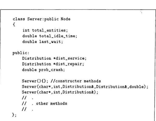
Server, in addition to those it inherits from SimObject and NODE, has
extra attributes to represent the structure and state of a processing entity:
-the total number of entities processed, -the total time that has been spent idle,
-the time point that the server has most recently started waiting,
-the distribution of service time for the incoming entities,
-the distribution of repair time in case of crashes,
-the probability of crash for the server.
The corresponding class definition is given in Figure 3.2.
In C-|--f-, a method having the same name with its class is treated as a con structor. In Figure 3.2 there are three constructor methods. The first of these is the default constructor that is called when no parameters are supplied by the program. The other two methods specify different ways of creating a server ob ject, the first with five parameters and the second with three parameters. The reason for this is that in some applications the crcish probability and the repair
CHAPTER 3. DESIGN OF THE CLASS LIBRARY 22
class Server:public Node
int total_entities; double total_idle_time; double last_wait; public: Distribution *dist_service; Distribution *dist_repair; double prob_crash;
Server(){}; //constructor methods
Server(char*,int.Distribution*,Distribution^,double); Server(char*,int.Distribution*); / / . // . other methods / / . };
Figure 3.2. The definition of SERVER
time distribution of the server may not be used. Then the parameters to be supplied to the constructor are the name and the id of the SERVER object (at tributes coming from the superclasses) and the service time distribution only. The no-crash and crash cases are represented in the constructor declaration as in Figures 3.3 and 3.4, respectively.
The declarations of the single-queue/single-server application are given in Figure 3.5. This code fragment is used to create SOURCE, QUEUE, SERVER
and Si n k objects.
System objects, after their declaration, can be linked to each other to au tomatically navigate the entities through the system. These links are declared by the SetLinks method of the objects. Each object can specify its input and output links by this method. The input link denotes the node entities are received from, and the output node denotes the node entities are sent to.
CHAPTER 3. DESIGN OF THE CLASS LIBRARY 23
Server::Server(char* n,int sid,Distribution* ds)
{ name=malloc(strlen(n)+l); strcpy(name,n); id=sid; status=IDLE; dist_service=&ds; total_entities=0; total_idle_time=0.0; last_wait=0.0; type=oServer; insert_to_objlist(this); }
Figure 3.3. Constructor of SERVER object for the iio-crash case
Server::Server(char* n,int sid,Distribution* ds, Distribution* dr,double p) { najne=malloc(strlen(n)+l); strcpy(name,n); id=sid; status=IDLE; dist_service=*ds; dist_repair=*dr; prob_crash=p; total_entities=0; total_idle_time=0.0; last_wait=0.0; type=oServer; insert_to_objlist(this); }
CHAPTER 3. DESIGN OF THE CLASS LIBRARY 24
Source S0("Source",0,dist_arrival); Queue QU("Queue",0);
Server SE("Server",0,dist_service); //no crashes Sink SI("Sink",0);
Figure 3.5. Object declarations of the single-queue/single-server application For the single-queue/single-server case, SOURCE sends the generated enti ties to Queue, Queue sends the entities coming from the source to SERVER
and Server, after servicing the entities coming from QUEUE, sends them to
Sink. The declaration of these links is as in Figure 3.6.
S O .SetLinks(SO,QU) Q U .SetLinks(SO,SE) SE.SetLinks(QU,SI)
Figure 3.6. Object links for the single-queue/single-server application The use of constructor and SetLinks calls make up the representation of the model in terms of system objects. At this point, the objects are ready to process as defined in their methods. But the synchronization and execution of the processes are determined by the events of the system. To run the model, the programmer should also indicate the events of the system.
3.2.2
R u n n in g th e m od el
The running of a model can roughly be described as the continuous execution of events in the system. Before describing this process, it is necessary to define the object which controls the state evolution of the model. This object is of the Simulation class; each simulation application either uses an object of this
class or derives a new class from it.
The attributes of a SIMULATION object are the current time point of the simulation run, a chronological list of events to occur, and a status variable (Figure 3.7). The methods are as follows:
CHAPTER 3. DESIGN OF THE CLASS LIBRARY 25 class Simulation { public: double SimClock; EventList PEL; int SimStatus; friend SimEvent; S i m u l a t i o n O ;
virtual void Init(); virtual void S t e p O ; virtual void Run(); virtual void Done(); virtual int S h o u l d S t o p O ;
};
Figure 3.7. The definition of SIMULATION
-a void constructor
-Hiit is called to set some application specific values before the execution of the simulation
-Step executes the next event to occur
-Run executes events until the stopping condition of the simulation is ful filled
-Done is called after the simulation to display statistical results
-ShouldStop checks, before the execution of each event, whether the simu lation is to continue
Run, after calling ShouldStop, invokes Step to carry out the simulation. The
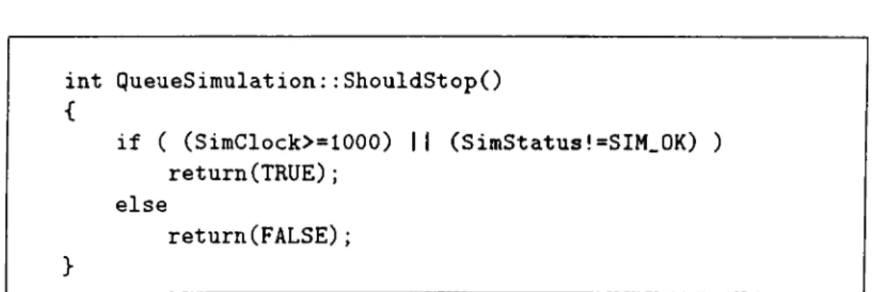
user can override ShouldStop to define the stopping condition of the program. Examples of the stopping condition can be a particular status of one of the system objects, a bound on the total number of entitites processed by the system, or a time limit. The code fragment in Figure 3.8 denotes the ShouldStop method of our single-queue/single-server example which stops the execution after 1000 units of time have elapsed.
CHAPTER 3. DESIGN OF THE CLASS LIBRARY 26
int QueueSimulation: : ShouldStopO
{ if ( (SimClock>=1000) || (SimStatus!=SIM_OK) ) return(TRUE); else return(FALSE); }
Figure 3.8. An example ShouldStop method
The simulation is carried out by executing the events that are retrieved from the eventlist of SIMULATION. These events are either inserted to the list (scheduled) by the programmer explicitly or the execution of an event can schedule another event in a triggered fashion. For example, considering the arrival of an entity to a queue, if the queue is empty at that time and the server that takes input from the queue is idle to accept the entity for service, then the removal of the entity from the queue and the start of service for that entity can be automatically scheduled. (Otherwise the entity is forced to wait in the queue.)
Done is used to display the results of the simulation run. This is accom
plished as follows. All system objects are kept in a list that is maintained by the system. Insertion of objects to this list is handled by the constructors.
Done sends a message to all these objects in the list to invoke their StatPrint
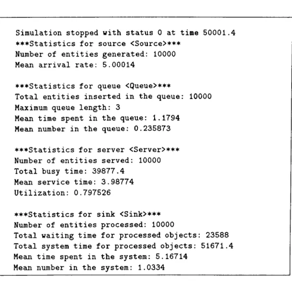
methods which output statistical information related to their object. A sample output for our single-queue/single-server application is presented in Figure 3.9.
The body of a simulation program mainly consists of /mf, Run^ and Done. These methods correspond to the modeling, running, and experimentation phases of a siniulation application, respectively. The catch is that Init per forms only some initializations while the components of the model are defined as object declarations browsed from the library.
CHAPTER 3. DESIGN OF THE CLASS LIBRARY 27
Simulation stopped with status 0 at time 50001.4 ♦♦♦Statistics for source <Source>^^^
Number of entities generated: 10000 Mean arrival rate: 5.00014
♦♦♦Statistics for queue <Queue>^^^
Total entities inserted in the queue: 10000 Maximum queue length: 3
Mean time spent in the queue: 1.1794 Mean number in the queue: 0.235873
♦♦♦Statistics for server <Server>^^^ Number of entities served: 10000 Total busy time: 39877.4
Mean service time: 3.98774 Utilization: 0.797526
♦♦♦Statistics for sink <Sink>^^^ Number of entities processed: 10000
Total waiting time for processed objects: 23588 Total system time for processed objects: 51671.4 Mean time spent in the system: 5.16714
Mean number in the system: 1.0334
Figure 3.9. Sample output from the method Done
3.3
S ch ed u lin g and e x e c u tio n o f ev en ts
There are two types of system-event objects: StaBLEObject denotes the
state changes for the system-objects derived from NODE and MovingEvent
is associated with CARRIER. The class definitions for these two classes and their base class are shown in Figure 3.10.
The base class SiMEVENT includes attributes denoting the time and type of the event and the system object which the event effects. There are also links to the next event to occur and to the SIMULATION object that owns the event. Derived from this class, StaBLEEvent has an extra attribute to hold
the entity that is the object to be processed by the event. The other subclass,
CHAPTER 3. DESIGN OF THE CLASS LIBRARY 28 class SimEvent p ublic: double time; int type; SimObject* owner; SimEvent* next; Simulation* sim; friend EventList; friend Simulation;
virtual void Print(ostream&){}; virtual void Execute(){};
virtual void SetSim(Simulation*); double G e t T i m e O ;
>;
class StableEvent:public SimEvent
protected: Entity *object; friend EventList; public: void Print(ostreami); >;
class MovingEvent:public SimEvent
{
protected:
SimObj ect *departure_point; SimObject *arrival_point; public:
void Print (ostrezunft);
};
CHAPTER 3. DESIGN OF THE CLASS LIBRARY 99
nodes for transportation events.
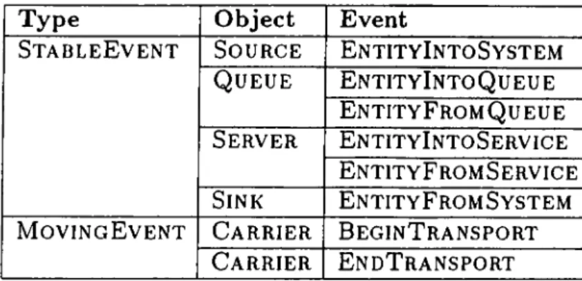
SIMLIB provides a list of standard events (Table 3.3). The programmer is free to define events for other actions. Each user-defined event object should incorporate the methods for constructing the object properly. Another method that should be defined is Execute. This method declares the actions to be performed when the event occurs.
Type
StableEvent
MovingEvent
Object Event
Source EntityIntoSystem
Queue EntityIntoQueue
EntityFromQueue
Server EntityIntoService
EntityFromService
Sink EntityFromSystem
Carrier BeginTransport
Carrier EndTransport
Table 3.3. List of event classes provided in SIMLIB
The events are kept in the FEL (Future Event List) attribute (an instance of
EventList) of the Simulation object in chronological order. FEL includes
two mostly used methods: one to insert new events with respect to the value of their time attribute and another to remove the next event from the list for execution.
Each event class has its Execute method which is invoked when the Step method of the simulation object retrieves it from the event list. The Execute methods perform the actions to represent the state changes of the system. They mainly call the methods of their owner objects for this purpose. In many cases, the execution of an event triggers another event and new events can be scheduled. To illustrate the scheduling and execution of events, we conclude this section with the code of the Execute method of EntityIntoService
CHAPTER 3. DESIGN OF THE CLASS LIBRARY 30
void EntitylntoService::Execute()
{
double duration;
//invoke the server's BeginService method owner->BeginService(object.time);
//compute the service time duration=(owner->GetDist())->generate();
//schedule the event for end of service sim->FEL.schedule(new EntityFromService
(time+duration,owner,object));
}
Figure 3.11. A sample Execute method
3.4
M apping a m o d el to a program
In the preceding sections, the steps of developing a simulation application within our framework were briefly described. In this section, we combine these ideas in the form of a methodology.
Before starting the coding process, a verified model of the system to be simulated should be ready. The model should focus on two aspects of the model: system components like queues, servers, or carriers, and events of the system. If no extra behavior is required, then system objects and events can be directly browsed from the library. Otherwise, the programmer should derive new classes representing the application-specific elements of the model.
Objects, whether system-defined or user-defined, are introduced to the pro gram along with their constructor calls. The constructor calls will insert the objects in a system-maintained list that can be used for debugging and out put purposes. For compatibility with the system-objects, user-defined objects should inherit the necessary methods (or they would override the inherited methods with proper implementations).
CHAPTER 3. DESIGN OF THE CLASS LIBRARY 31
The links between objects can be declared with the SetLinks methods of the objects. To do this call, each object should have one input and output link. If there are multiple links, then the decision for the navigation of objects should be coded into the methods of the derived system-object or into the Execute method of an associated event object.
User-defined events can be employed to add extra behavior to the system. This is done with the implementation of the Execute methods of the defined events. Most system-events trigger other events for the continuity of the execu tion; the same paradigm applies to user-defined events. (The event list should never be empty.)
Once the definition of the system-objects and events are coded, the last step is to define or derive an object (of type SIMULATION) for the control of execution. The Init method of this object schedules the initial events which enforce the SOURCE objects of the system to generate new entities. These events trigger other events which in turn invoke the system-objects to simulate their cissociated behavior. The execution lasts until the stopping condition (available in ShouldStop) occurs.
Once the above steps are carried out, only a small amount of code is re quired to finish the implementation. An example of such a main body that uses a derived simulation object for a single-queue/single-server is presented in Figure 3.12.
QueueSimulation QS;
//control object derived from Simulation class
int m a i n O
Q S . I n i t O ; QS.Run(); QS .DoneO ; }
C h a p te r 4
Im plem entation
The purpose of this chapter is to study the implementation of SIMLIB. The most important task in this regard was the definition of the classes. First we give a detailed description of these classes—their attributes and methods. Then, communication among the objects of an application is described. The addition of user-defined behavior to applications is treated next. The last section considers the system-maintained services provided by SIMLIB.
4.1
D efin itio n o f classes
SIMLIB has been implemented using the C-|--|- programming language on SUN Workstations running under the UNIX system. C-t--|-, inheriting the portability of the C, has received wide acceptance from both academic and industrial users. The broad range of functionality of the language (combined with its availability on every UNIX system) has been the major reason for our preference.
Before studying the classes in SIMLIB, we want to describe the notion of
virtual functions. The use of dynamic binding, i.e., the relating of a procedure
with its data at the time of execution, is one of the key properties of OOP. C-f-1- supports dynamic binding through virtual functions. A virtual function allows overriding of a function name. Each subclass within the hierarchy can choose a different implementation for this function. For example, in a graphical environment that uses a hierarchy of classes to represent different shapes like