SIGNAL PROCESSING PROBLEMS AND ALGORITHMS IN DISPLAY SIDE OF 3DTV
E. Ulusoy1, G.B. Esmer1, H.M. Ozaktas1, L.
Onurall,
A. Gotchev2 and V Uzunov2
1
Bilkent University, Department of EEE TR-06800 Bilkent, Ankara, Turkey
2
Tampere University of Technology, Institute of Signal Processing FIN-33101 Tampere, Finland
ABSTRACT
Twoimportant signal processing problems in the display side
ofaholographic3DTV arethecomputation of the diffraction field ofa3Dobject from its abstract representation, and
deter-mination of the best display configuration to synthesize some intended light distribution. To solve the former problem, we
worked on the computation of ID diffraction patterns from discrete data distributedover 2Dspace. Theproblem is solved using matrix pseudo-inversion which dominates the
computa-tionalcomplexity. Then, the light field synthesis problem by
adeflectable mirrorarraydevice (DMAD) isposedas a
con-strained linearoptimization problem. The formulation makes direct application ofcommon optimization algorithms quite
easy. The simulations indicate that developed methods are
promising.
Index Terms- 3DTV, scalar diffraction, light field
syn-thesis, deflectable mirrorarray device 1. INTRODUCTION
Theholographic display and the associated signal processing algorithms are theintegral components ofaholographic 3D
television system. The main function ofa holographic dis-play istosynthesizeacomplex light field whichprettymuch resembles the original light field that would emergefrom a 3D scene if it was illuminatedby somecoherent lightsource, sothat the observers wouldseetheoriginalscenewithout its actualpresence. Wefirstly needsomeinformation about the diffracted light field. Onepractice isto extractthe three di-mensional information about theobject itself through com-putergraphics techniques, and provide the display end with
someabstract information such as ameshstructurewith tex-tureinformation, etc. Therefore, oneof the main tasks of the display end becomes the computation of the diffraction field that wouldemanate from the3D scenewhich is described in
abstractterms. Unfortunately, computation of diffraction field
over3D spacebringstoomuchcomputational burden. Hence,
we concentrate ontheproblem of calculation ofID diffrac-tionpattern on aline from distributedsamplesover2Dspace. Inmostof the earlierworks, straightforward superposition is This workis supported byECwithin FP6 under Grant511568 with
acronym3DTV.
usedtocomputeof the diffractionpattern[1]. Anappropriate calculation method whichprovidesasimultaneous solution is
presented in sec. 2.
After the determination of the diffraction field of the
ob-ject,thesubsequent task istosynthesize this field. Given the diffractionfield,one mustcomputethedriving signalsor
opti-mumconfiguration for the display such that the intendedfield
is recreated to the best extent. We dealt with this second main
signal processing problemin sec. 3. WechoseDMAD asthe display device. The mirrorsonthis devicecanbe tiltedto
con-trol the outputlight field. Firstly, weanalyzed the light field generated by this device upon acertain configuration.
Sec-ondly, for this device, weformulated thelight field synthesis problemin alinear constrained optimization problem frame-work, for whichamyriad of optimization algorithms exist and
canbeadapted.
2. CALCULATION OF SCALAR OPTICAL DIFFRACTIONDUETO DISCRETEDATA
Calculation of scalaroptical diffractionpattern on aline due
to a setof discrete data distributedover 2D spaceis atricky problem. Superposition of the individual diffractionpatterns
of the datapoints maygiveerroneousresults. Tojustify this fact, twoscenarios will beinvestigated. Inthe first scenario, the field is completely specified onall the datapoints of the input line which is parallel to the output line. In this
sce-nario, the problem can be formulated within a linear shift-invariant systemframework, sothe diffractionpattern onthe
outputlinecanbe calculatedby convolving the inputpattern
and the diffraction kernel. In the second scenario, the field is not specified on oneof the sample locations of the input line. Instead, an additional value isprovided at asample lo-cation outside the input line, to compensatethe information loss duetothemissing data. Inthisscenario, the dataonthe input line and the complementary data are affectedby each other. Hence, the method that calculates the diffraction field should take this interaction into account. Here, wepropose
such amethod. Given discrete data is arbitrarily distributed
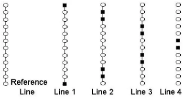
over 2D space andwe useparallel lines torepresentthe2D space. Some of the samples on eachparallel lineare speci-fied while others are unknown. Figure 1 illustrates atypical
case. AsitcanbeseenfromFigure 1, each line contains black
trixBwhich provides the transformation from f to g is ej7r(do ejNIdo eiN7 l e N(d B =K L eN dN-1 ejNidN-2 ej NIdN-1 ej3N dN-2 .eido uReference
Line Line Line 2 Line 3 Line4
Fig. 1. An Illustration ofa set of distributed data over 2D
space.
squares and circles. Black squares stand for knownsamples,
while circlesrepresentthemissing data. Usingthe available
data,ourmethod calculates thesamplesof the diffraction field
on aseparatereference line.
2.1. Basic Theory
The relation between diffractionpatternsontheinputline and theoutputline is
u(x,z) (x)*
u(x,O)
where u(x,0) represents thediffractionpatternon the input
linewhich is located atz = 0 and u(x, z) is the calculated
diffractionpatternontheoutputlinewhich is parallel tothe
input line [2]. Spatial domaincoordinates arerepresented by
the variables x and z. The diffraction kernel under Fresnel
approximationis
hz(x) j= ejJ2x (2)
where the parameter k is the wave number. The parameter
A is the optical wavelength. As it can be seen from Eq. 1
andEq. 2, when the input and the output lines are parallel
toeachother, the diffraction kernel becomes shift-invariant. Moreover, ifweknowthe dataon a linecompletely, we can
compute the diffraction patternover the entire 2D spaceby
using the relationship given by Eq. 1.
Theproposed method is basedondiscrete computations.
Therefore, Eq. 1issampled andweget,
g= Bf
whereB representsthesampled diffraction kernel. Details of sampling procedure is given in [3]. Vectors f and g arethe
samples of u(x, 0) and u(x, z), respectively. The diffraction patternson u(x, 0) and u(x, z) areuniformly sampled.
Ma-where the termKprovides constantphase shift and magni-tude attenuation. The variable d(m n) is equalto (m -n)2
wheremandnaretheindices of thevectors f andg,
respec-tively. The variable N is the number of sampleson aline. The
parameter NAX2 where X is the spatial sampling period along x-axis.
Wedefine anothermatrix, BBF, from therowvectors of the B matrices. BBF gives the relationship between the dif-fraction field on the reference line and the distributed data over 2D space. Dimensions of BBF is determined by the
variable Nand the number of the given data, s. Thevectorf
iscomputed by
f=BBF g (5)
where
BBF+
is thepseudo-inverse of BBFand thevectorg'representsthediffraction dataoverthe distributed data points.
Theproposed methodcanbe extendedto 3Dby storing each
2Ddiffraction field ina IDvector,but in thiscasethe
dimen-sions of BandBBFmaybecomeunmanageable.
2.2. Simulation Results
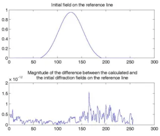
Theproposed method is tested by settingacontrolled
exper-iment. Inthis experiment, an initial field as shown in Fig-ure2isdefinedonthereference line. Theexperiment is
com-prised of 256 parallel lines over 2D space with N = 256
samples per line. After then, we randomly pick 256 data
points. The spatial samplingperiod along the x-axis is set to
A/2. The distance between the reference line and the
clos-est line which contains the given data is set to NA/4 and the distance between each data lineis A/2. BBF matrix is obtainedaccording tothe locations of the given data points. Then, Eq. 5 provides the diffraction field on the reference
line. Inthis simulation, theparameter s, which is the
num-ber ofthe known terms, and the variable N are equal. In
mostcases, sand Ntake different values. Therefore,we
cal-culate thepseudo-inverse of BBF to obtain the least-square solution. Figure 2 provides the magnitude of the difference between the initial and the calculated diffraction fields on
the reference line. Thecomputational burden is estimatedas
(sN2 -N3/3) when Householder transformation is used
tocalculatepseudo-inverse of BBF.
3. 3DLIGHT FIELDSYNTHESIS WITH A DMAD Inthispart,weseektheimplementation ofaholographic
dis-play with aDMAD. The DMAD is areflection-mode SLM,
whichconsists ofatwo-dimensional array ofsquare shaped
2986
08 tl " (X) =exp{j
Tc
TORo,K
(Ro,
(x-
T)) (7)0.6 kI eI
0.4-02- - wherexis the position vector given byx [ x y z
]
5 0 5 20 25 30 and li is the direction cosinesvectorof the planewavegiven
0 50 100 150 200 250 300T
byis [ ae p ]TwiththeconstraintaO2+p2+.y2 =1.
Magnitude of the difference between the calculatedand Ty i byEq.h6,eandtrainis2givenas
X1 1 the initialdiffraction fieldsonthereference line TiiS the matrixgiven by Eq.6,andRoiSgivenas:
cos0 1
112- cosO v2
-sin 0 0
50 100 150 200 250 300
Fig. 2. Initial diffraction field on the reference line and the magnitude of the difference between the calculated and the
initial diffractionfields on the reference line
micro-mirrors. The mirrors can be tilted along their diagonal
axis. The deflection of each mirrorcan be controlled
sepa-rately. PracticalDMADsconsist of a large number of mirrors,
typically inthe order of106 mirrorsperchip. This enables
themtocontrolalarge number of degrees of freedom[4]. Onepossibleway tomanipulate light with this device is by cleverly tilting the mirrors onthe device and illuminating the device with laserlight,sothat the reflected and diffracted light will approximateanintended light field. The key issue
thenturns outtobe the determination of the tilt angles of the mirrors accordingtothetargetfield. In a 3DTV setting, this mustbe done within areasonabletime compatible with
real-timeoperation. Itshould also be noted that the large number of mirrorsonthe device resultsin achallenging problem with
veryhigh dimensionality.
Below,wefirstly provideananalysis of the fieldproduced
by this device. Secondly, we pose the light field synthesis problemas alinear constrained optimization problem. 3.1. Light Field Generatedby A DMAD
The mirrors of theDMADcanbeindexed with a column vec-tori
=[
m n ]T withm,n eZ,
such that thei'th mirroris centered around:
1
11i
1 I
L 0 0]J
where 2W isthe width of themirrors and L is the length of thespacing between the mirrors.
Afterillumination withaplanewave exp{j2 Jx}, the
fieldproduced by the i'th mirror, when it is tilted byanangle
1
sinO
1v21
sinO
2 Cos01j
(8)
Weexpressthe resultsby appropriately modifying the six
parametersof the function:
a
oz a
IT[
XY
Z]T)
h(x,
y)Dx)Y
rect (2) rect (2Wi)
exp
{j
(ax + IY)} (9) wherein ourcalculations h (x, y) is the Fresnel impulse re-sponse of freespace andgx,y
denotes 2D convolution in x andycoordinates. Detailedexpressions maybe foundin [2].Total field is obtainedbysuperposingthe individual con-tributions of mirrors.
3.2. Linear ConstrainedOptimization Problem
Formula-tionforComplex Light Field Synthesis withaDMAD Due tothequite complex and nonlinearrelationship between
tiltangles and produced fields (Eq. 7), direct manipulation of theexpressions of previous section for the inverse problem is
notagoodstrategy. Instead,wewill considerthe formulation
below.
AssumetheDMADconsist ofM x Nmicromirrorsand
each micromirrorcanbe tunedtoS C Z+ discrete tilt angles.
For convenience, letus usehere a onedimensional notation
for the mirrors which are finiteinnumber. Denote the field generated byj'thmirror (j C Z, 1 <j < M x N) when it is tiltedto s'thposition (s C Z, 1 < s < S)by
uj,
(x), and the desired fieldbyb(x).
Ouraim istofindouttheoptimum tiltangle for each mirror such thatb(x)
is synthesizedtothe bestextent. Thereareseveral constraints associated with this inverseproblem: during the synthesis ofaframe, all thepos-sible fieldsuj
(x)
cannotbe utilizedsimultaneously. Exactlyoneof thesfieldsproduced by each mirrorcanbeemployed
at atime. Theamplitudes of the selected fields arerestricted
tounity.
Upon theseobservations, the total fieldu(x)produced by theDMAD canbeexpressedinthefollowing form:
u(x)
=E E
Pjs
uj,(x)
(10)
j s 2987 2 1.5 0.5 0 0T
c Ti = YcLO
(W 2+L\)
Oi
isgiven by:
Here, for each j, only one of the coefficients
Pjs
is unity,while theremainingare zero.
The next step is the digitization of the information present inthe analog light fields. When Fresnel approximation is
con-sidered for diffraction, light fields emerging from spatially bounded objects can be represented fully by their samples taken at finiterates [5]. In a general case, the number of
required samples is infinite, whereas, in our work, we assume
thatafinite number ofsamples areenoughtocharacterize the fields. Thus,werepresent
uj,
(x) andb(x)by the finite sizedvectors
uj,
and b. After all,we get:Dp= b
Reconstructed Circular Object
20 20
(1 1)
where {(j-1) x S + s}'th column ofD is uj, andp C IR(MxNxS)xissuchthatforallk Z,1 < k< MxN; the sub-vector p[(k -1) x S+1: k x S] isequal to a column of theSx Sidentity matrix.Inwords, the matrixDencloses thesamples of different fields produced by the DMAD, hence
represents the device. Vectorbrepresentsthe specified field. Thep vector,which istobe solved for, will dictate the choice of tiltpositions for the mirrors. Manyalgorithms exist for this class ofproblems.
3.3. SimulationResults
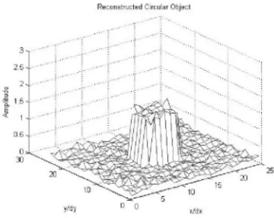
Wehave carriedout a simulationto illustrate the usefulness ofourformulations. Weconsidered a 71 x 71 DMADwith
16,um x 16,ummirrors that could be tiltedto-12,0and 12
degrees. The interspacing between the mirrors wastaken as l,um. The target fieldwas represented by its 25 x 25
sam-ples uniformly taken on apatch that residedat a distance of
z = 853,um to the device. The sampling intervals became
dx = dy = 53,um. Inparticular, we tried to synthesize a
circular field distribution of15circ ( 2 The
device was normally illuminated by a plane wave of A =
633nm. We applied simulated annealing algorithm to
con-figure the device such that the samples of thetargetfieldwere
reconstructed with minimummeansquarederror.
To arrive at the format suggested by Eq. 11, we firstly prepared matrix D by computing the samples of the fields produced by mirrors of the chip onthesampling patch. We
made extensiveuseof the formulas developed in sec.3.1 for thatpurpose. In our case, size ofD became 625 x 15123.
(Thereare 71 x 71 x 3 = 15123different fields andwetook
25 x 25 = 625 samples for each field.) Vector b (625 x 1)
contains thesamples oftargetfield. Wetriedtosolvep.
The reconstruction weobtained is showninFig. 3. The finalerroris 5.8%.
While still there are many open questions waitingto be answered aboutproper application of the developed frame-work, this initial simulationsuggeststhatourapproach is handy
indealing with this synthesis problem.
Fig. 3. Reconstructed field 4. CONCLUSION
This work contains efforts to solve thetwo central problems associated withholographic 3DTV. Theproposed algorithm for the firstproblemcanbe usedtocalculate diffraction pat-tern over 2D spacefrom an arbitrary curve. The algorithm provides linear solution and its computational complexity is dominatedby the computation of the pseudo-inverse of BBF matrix. Forthe secondpart, weundertook thelight field
syn-thesisproblem with aDMAD. An analysis of the light field generated by the device is given. The derived formulas are
useful in calculating the field of the mirrors to be utilized during the solution of the inverse problem. At afirstglance, the inverseproblemseems tobecomplex. However, wehave shown that itcanbecastinthe format ofalinear constrained optimization problem, for which many fastalgorithms exist andcanbeadapted.
5. REFERENCES
[1] M. L.Huebschman,B.Munjuluri, andH. R.Garner, "Dy-namic holographic 3-d image projection," Optics Ex-press,vol. 11,pp.437-445, 2003.
[2] J. W. Goodman, Introduction to Fourier Optics,
Mc-Graw-Hill,NewYork, 1996.
[3] L. Onural andP. D. Scott, "Digital decoding of in-line holograms," Optical Engineering, vol. 26, pp.
1124-1132, 1987.
[4] L.J. Hornbeck, "Digital light processing update: status
and futureapplications," in ConfonProjectionDisplays
V4
ProcSPIE, 1999, vol. 3634,pp. 158-170.[5] L. Onural, "Sampling of the diffraction field," Applied Optics, vol. 39,pp.5929-5935,2000.