Permanent tuning of optical resonant modes of
chalcogenide-coated microresonators
Ersin Huseyinoglu,
1,* Erol Özgür,
1Gökhan Bakan,
2Bülend Ortaç,
1AND
Aykutlu Dana
31Bilkent University UNAM—Institute of Materials Science and Nanotechnology, Ankara, 06800, Turkey 2National Graphene Institute, University of Manchester, Manchester, M13 9PL, UK
3E.L. Ginzton Laboratory, Stanford University, Stanford, California 94305, USA
*Corresponding author: [email protected]
Received 16 March 2020; revised 22 April 2020; accepted 24 April 2020; posted 27 April 2020 (Doc. ID 392924); published 26 May 2020
Chalcogenide materials are promising for optical resonant mode tuning of whispering gallery mode (WGM) microresonators due to their high nonlinearity. In this study, this phenomenon was demonstrated for Ge2Sb2Te5
-coated toroidal microresonators using an optical postprocess, which utilizes the intrinsically photosensitive property of the Ge2Sb2Te5coating. A signal laser was used to illuminate the resonator for permanent tuning of the
WGMs in a sensitive manner. 0.01 nm and 0.02 nm permanent tuning of the WGMs was recorded for 5 nm and 10 nm coated resonators, respectively. This technique enables resonance matching of coupled optical resonators, which could pave the way for optoelectronic circuitries employing multiple optical microresonators. © 2020 Optical Society of America
https://doi.org/10.1364/AO.392924
1. INTRODUCTION
Similar to acoustic whispering gallery modes, discovered by Lord Rayleigh upon noticing the whisper sounds could be heard from another side of the cathedral’s dome [1], optical whis-pering gallery modes (WGM) can occur at optical resonators resulting in high confinement of light, which has the fastest traveling speed known, in a very small volume. The research on the WGM optical resonators intensified in the last decades due to their exceptional characteristic of light confinement and utilization of confined photons. Due to the growing attention for photonic circuits, the need for light generation and modu-lation applications of microresonators increased. The WGM optical resonators can be utilized for various applications, including chemical and biological sensing [2,3], optomechan-ics [4], nonlinear and quantum optics [5], Raman lasing [6], and all-optical modulation of light [7,8]. Different geometries (disk, ring, spherical, toroidal) [9,10] and different methods of coupling (optical fiber half-coupler, free-space light coupling, coupling with tapered fiber) [11,12] are being used for WGM resonator-related research, where each geometry and each method have their own advantages and disadvantages. While planar geometries (ring, disk) providing ease of fabrication and integration that can be achievable with current microfabrica-tion techniques, they suffer from having lower quality factors (Q-factors), a figure of merit for optical resonators that defines the amount of optical energy that can be stored within the resonator. Spherical and toroidal resonators have much higher
Q-factors while their fabrication process and integration are relatively harder to achieve. The fabrication of the toroidal res-onators involve a thermal process to induce surface-tension for reshaping the previous geometry of a microdisk into a toroidal geometry [9], while spherical resonators can be produced by melting the tip of a fiber [13].
Several techniques for obtaining tunable optical resonators have been proposed, among which the most common one is thermo-optic tuning. Kavungal et al. demonstrated
thermo-optic tuning by utilizing a capillary-based WGM resonator filled with liquid crystals [14]. The nematic liquid crystal is used for its thermo-optic properties in order to get a response under thermal stimuli, which creates a blueshift in the resonant modes. Another work by Jonášet al. utilized liquid crystals in the
form of optically trapped droplet resonators in order to modify the phase of the liquid crystals with temperature change that leads to a shift in the mode spectrum [15]. It is also possible using polymer-based resonators to get a similar thermo-optic effect as Anandet al. showed by using polymethyl
methacry-late (PMMA) hollow optical fiber resonator by utilizing the PMMA’s negative thermo-optic coefficient, which dominates the total shift against thermal expansion component [16]. It is also possible to tune the resonant mode spectrum with electrical stimuli as Wanget al. demonstrated in their research on lithium
niobate (LN) resonators [17]. Wanget al. produced a different
type of LN resonators, and, by applying a potential difference, they achieved a shift in the mode spectrum by utilizing the
Research Article Vol. 59, No. 16 / 1 June 2020 /Applied Optics 4815
electro-optic properties of the LN. Electro-optic modulation was also achieved with silicon microspherical resonators [8] by changing the refractive index of the resonator with applied potential difference.
Although the WGM microresonators proved to be effective for a variety of applications, their large scale and commercial applications failed to be realized due to several restrictions, mostly because of fabrication and integration limitations. One of the obstacles that prevents the large scale utilization of microresonators is the production of microresonators with exactly the same resonant mode spectra due to the small devia-tions inherited from the fabrication process. These deviadevia-tions led to slight mismatches in the optical properties of the fabri-cated resonators, even for the same production batch. Although it is possible to modify and modulate the resonant modes in a facile and reversible way, performing an irreversible and perma-nent tuning of resonant modes can also be facilitated to provide a possible solution to correct these deviations.
Chalcogenides, due their high nonlinearity, wide mid-IR transparency, and low-phonon energy, are being utilized for a variety of optical applications [7,18]. Ge2Sb2Te5 (GST) is a
phase-changing material that is utilized for applications, such as color switching [19] and IR spectroscopy [20]. Phase change in a chalcogenide can also be induced by light exposure due to its photosensitive nature [18]. Light exposure induces structural changes within the material and can cause the phase change at the exposed area. This phase change accompanies a change in the material’s optical properties, i.e., refractive index and absorption. Due to the change in the absorption, this process can also be referred to as photodarkening. If the chalcogenide material is being utilized as an optical resonator, any alteration to the refractive index manifests itself as a shift at the reso-nant modes. Previous reports demonstrated a similar effect on chalcogenides and the utilization of this effect. Weidenhof
et al. induced crystallization on Ge2Sb2Te5 films by using a
laser [21]. Faraonet al. showed tuning of mode resonance of
crystal cavities by using photodarkening on chalcogenides [22], and later Luanet al. demonstrated the photoinduced refractive
index change on chalcogenide microfibers [23]. Kabakovaet al.
studied and reported photoinduced refractive index change in arsenic selenide fibers [24]. Schlichet al. utilized the
fem-tosecond laser to induce change on the phase change materials to achieve color switching [25]. A similar research also uti-lized highly nonlinear chalcogenide to demonstrate all-optical switching in long period fiber gratings [26]. Here, we suggest a method for permanently tuning optical microresonators formed by subsequent use of a well-established silicon-based microfab-rication technique, followed by a photosensitive Ge2Sb2Te5
sputtering. Permanent tuning in the resonance mode of the Ge2Sb2Te5-coated silica toroidal resonators was demonstrated
via changing the refractive index of the coating layer induced by the crystallization (phase change) with laser exposure.
2. MATERIALS AND METHODS
A. Materials
The silicon wafer used in this work has a 500 micron thickness with 2 micron thermally grown oxide layer on top, purchased from Addison Engineering. The silica optical fiber purchased
from Thorlabs was SMF-28, 125 micron cladding with 8 micron core sizes. The photoresists and chemicals used in the microfabrication were hexamethyldisilazane (HMDS), AZ 4533, AZ400K, and Buffer Oxide Etchant (BOE 7:1) as purchased from Merck.
B. Resonator Fabrication
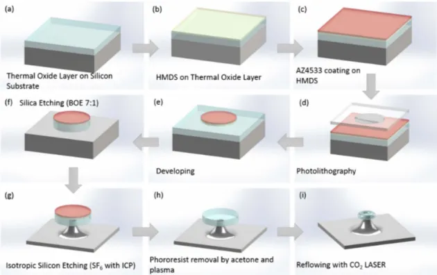
Toroidal silica microresonators were fabricated by using well-established silicon microfabrication methods as schematically shown in Fig.1. Thermal oxide on silicon wafer was initially diced into 20 × 30 mm rectangular pieces, and each piece was used to fabricate a series of resonators on top by using microfab-rication techniques [Fig.1(a)]. The 20 × 30 mm rectangular wafer piece was first spin-coated with the HMDS to increase the bonding between the photoresist and the thermal oxide layer on the silicon [Fig.1(b)], and then the wafer was coated with AZ4533 photoresist for further photolithography process [Fig.1(c)]. The resist was then patterned via photolithography by using a mask with disk patterns and then by developing with AZ400K chemical diluted with deionized water (DI-Water) with a volumetric ratio of 1:4 [Fig.1(d)and1(e)]. The resulting disk-shaped patterns protect the thermal oxide area under, so, by etching the wafer with BOE, the disk patterns on the photoresist were transferred onto the thermal oxide layer by anisotropic wet etching, hence creating silica disks on top of silicon ground [Fig.1(f )]. The wafer was then etched by inductively coupled plasma (ICP) isotropically to form silicon pillars under silica disks [Fig.1(g)]. The photoresist was then removed by acetone and plasma [Fig.1(h)]. The resulting silica microdisks on silicon pillars were reflowed by a carbon dioxide (CO2) laser in order
to reshape the disks into toroidal structures due to high tem-perature generated on silica disks, because of high absorption of the silica while the silicon pillar acts as a heat sink due to low absorption of CO2laser emission [Fig.1(i)]. Scanning electron
microscope (SEM) images of a fabricated toroidal resonator can be seen in Figs.2(a)and2(b). After successful fabrication of silica toroidal resonators on wafer, Ge2Sb2Te5coating with
a predefined thickness was done on top of resonators using sputtering.
C. Fiber Tapering
Tapered optical fibers, which are fabricated from standard optical fibers by heating and pulling, enable and enhance the evanescent field coupling, and they were proposed as an ideal coupling method for systems that require very low loss [12,27]. Due to its advantage regarding coupling efficiency, tapered fiber was used to guide and couple the light in this work. A standard silica fiber (SMF-28, 125 micron cladding with 8 micron core) was tapered by heating it with a hydrogen torch and simulta-neously pulling it toward opposite directions using two linear translation stages (Newport) controlled by a stage controller (Newport ESP300) connected to a computer. One end of the optical fiber connected to a laser system (Santec TLS-510) that can emit light between 1510–1650 nm as a probe laser, while the other end was connected to a photodiode connected to a pow-ermeter (Newport 1935C). Powpow-ermeter output was connected to an oscilloscope (Tektronix 1012B) that was synchronized to
Fig. 1. Microtoroid fabrication steps from oxide on silicon wafer to silica toroid on silicon pillar. (a) A silicon wafer with a thermal oxide layer on top is diced into 20 × 30 mm rectangular samples. (b) The 20 × 30 mm sample is coated with HMDS. (c) AZ4533 photoresist is then spin-coated onto the sample spin-coated with HMDS. (d) Photolithography is achieved with a mask with disk patterns. (e) Disk photoresist patterns formed on the thermal oxide layer after the developing process. (f ) Patterns transferred to the oxide layer by wet etching. (g) Silicon pillars formed by applying dry etching. (h) Photoresist is removed by wet and dry methods. (i) The toroidal resonators formed by reflowing silica disks with the CO2laser.
Fig. 2. SEM images of a toroidal microresonator from (a) top view and (b) side view. Optical images of a microresonator from (c) top view and (d) side view while it is coupled to a tapered optical fiber [3].
Research Article Vol. 59, No. 16 / 1 June 2020 /Applied Optics 4817
the laser system. Polymer coating of the optical fiber at the mid-dle section was removed (2 cm length), and fiber was fixed on two translational stages with the coating-removed part placed between two stages. A hydrogen torch was placed towards to the optical fiber so the flame from the torch heats the fiber and increases its temperature to conduct the pulling. The fiber was being pulled by the stages while the torch was heating it up, hence elongating it while the diameter was decreasing. In order to ensure an adiabatic tapering for efficient coupling and high transmission, the process was monitored via a camera. Fiber transmission was simultaneously monitored and recorded using a powermeter connected to a computer. In our fiber tapering process, we achieved subwavelength diameters (approx. 1 µm), which is the ideal case for enhancing the coupling efficiency. 3. EXPERIMENTS
The torch was removed from the setup after the fiber tapering process was achieved, and a three-axis piezoelectric stage was placed between the translational stages under the tapered sec-tion of the fiber. The wafers with toroidal microresonators on surface were fixed onto the three-axis stage (Thorlabs Nanomax-TS stage with Thorlabs BPC303 Controller), and, while the probe laser was being swapped the wavelengths between 1510– 1620 nm, the resonator was approached to the close proximity of the tapered fiber roughly [Fig.2(c)and2(d)], and then the fine tuning was done to match the perimeter of the toroidal res-onator to the tapered region of the fiber to achieve the coupling with high efficiency. The transmission of the probe laser oscillat-ing between the start and the stop wavelengths was monitored while the resonator was being moved to the close proximity of the tapered fiber. Observing the dips in the transmission spec-trum yielding the mode resonances demonstrates the coupling is achieved.
A resonant mode was selected, and then the probe laser’s new swap parameters were set accordingly to cover this mode only, and then the resonant mode was monitored while the signal laser (the DIY laser) was switched on and off to illuminate the resonator for tuning the resonances by phase-change-induced
refractive index change (photodarkening). The exposure time was chosen as 30 seconds for the samples. After the change in transmission spectrum was obtained, the signal laser was switched off, and the final transmission spectrum was recorded as well. This means that three different spectra were recorded including the initial (the Ge2Sb2Te5-coated samples), the laser
on state, and the laser off state. 4. RESULTS
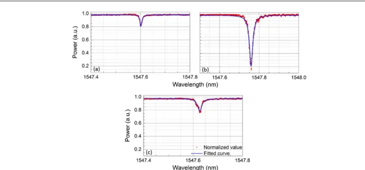
The resonant mode spectra for both samples were inspected prior to coating procedure, and the Q-factor of the resonators were reduced while sputter coating of the resonators. The Q-factor of the resonators depends on several contributing factors, such as absorption loss, scattering loss due to roughness, radiation loss, and loss due to contamination. Sputtering of the silica resonator samples with the chalcogenide resulted in increased surface roughness and absorption, which led to a decrease in the quality factor. Two sets of resonators were fab-ricated, and then their Q-factors were calculated prior to the chalcogenide coating.
The first set was coated with 5 nm, and the quality factor of the set dropped to 2.1 × 10⁵ [Fig.3(c)] from 2.7 × 10⁶prior
coating value [Fig. 3(a)]. The bare resonator’s quality factor from the second set was calculated as 2.5 × 10⁶[Fig.3(b)], and
it dropped to 3.2 × 10⁴after 10 nm thick chalcogenide
coat-ing [Fig.3(d)]. Figure3shows that the Q-factors are reduced upon coating for the samples with the 5 nm and 10 nm coating thicknesses.
Silica resonator samples with 5 nm and 10 nm Ge2Sb2Te5
coatings were illuminated by a custom-made blue laser (450 nm). Figure4(a)shows initial spectrum of the resonator from 5 m coated sample indicating the resonant mode of the coated resonator prior to optical tuning with the signal laser. The second spectrum [Fig.4(b)] gives the resonant mode while the tuning laser is switched on and illuminating onto the coated sample. Figure4(c)shows the tuned resonant mode when the laser is switched off after 30 s of the exposure time. When the signal laser is on, the shift in the resonant mode can be observed
Fig. 4. Resonant mode tuning with silica resonator with 5 nm Ge2Sb2Te5coating. The transmission spectrum (a) prior to the photodarkening via
signal laser illumination, (b) during the photodarkening, and (c) at the end of the photodarkening process (after signal laser is switched off ).
Fig. 5. Resonant mode tuning with silica resonator with 10 nm Ge2Sb2Te5coating. The transmission spectrum (a) prior to the photodarkening via
signal laser illumination, (b) during the photodarkening, and (c) at the end of the photodarkening process (after signal laser is switched off ).
due to the photodarkening and the thermal effect [Fig.4(b)]. While the material is exposed to the laser light, there is also temperature buildup on the resonator due to the laser heating. Temperature increase causes thermal expansion that increases the diameter of the resonator. The increase in the resonator diameter also leads to a decrease in the gap between the resonator and the tapered fiber. As a result of these changes, the optical path length of the light (which is the multiplication of the refrac-tive index and the distance traveled by the light, which is the diameter of the resonator in our situation) inside the resonator increases and manifests itself as redshift. The narrower gap between the resonator and the fiber causes a better optical phase matching condition resulting in higher coupling efficiency and lower transmission. However, this a temporary change, and it diminishes when the signal laser is turned off. When the
thermal expansion component, which is a contribution of the laser heating, is no more observed after switching off the tuning laser, the remaining spectral change is the permanent shift of the resonant mode due to the photodarkening of Ge2Sb2Te5
material coated onto the resonator [Fig.4(c)]. The permanent tuning was 0.01 nm for 5 nm coated sample.
Similarly, Figs.5(a)–5(c)demonstrate the results for 10 nm Ge2Sb2Te5-coated sample for the initial spectrum upon
coat-ing, the spectrum when the laser is on, and the spectrum of the resonator after exposure of the illuminated laser for 30 s, respec-tively. The same temporal temperature-dependent change in the resonant mode with lower transmission and higher redshift was observed for 10 nm sample, while the laser was on, and it diminished after the laser was switched off. The permanent optical resonance shift in the 10 nm sample was measured as
Research Article Vol. 59, No. 16 / 1 June 2020 /Applied Optics 4819
0.02 nm, as could be expected due to doubled thickness of the Ge2Sb2Te5layer that was affected by the photodarkening laser.
5. SUMMARY
In conclusion, Ge2Sb2Te5 layer deposited toroidal silica
res-onators were fabricated, and a chalcogenide layer was used for utilizing photodarkening (phase-change-induced refractive index change) in order to permanently tune the optical reso-nance of the WGM resonators. During the photodarkening, temperature-dependent mode shift and change in the coupling efficiency were observed because of the thermal expansion caused by the laser heating in both cases with 5 nm and 10 nm coated resonators. Increased optical path length due to increase in the resonator diameter as a result of thermal expansion caused a redshift (higher mode wavelength) in the mode spectrum. The decrease in the fiber transmission during the signal laser emission, which means a better coupling to the resonator, is possibly a result of a transient temperature change caused by the signal laser during the process, which alters the phase match-ing condition due to thermal expansion. The refractive index change caused by the phase change of the chalcogenide induced by the laser resulted in a 0.01 nm shift for the 5 nm coated sample, while the process caused 0.02 nm shift in the resonant mode for the 10 nm sample. Following the laser-induced phase change process, the refractive index of the Ge2Sb2Te5layer was
increased due to the crystallization of the light exposed chalco-genide. This increase in the refractive index of the chalcogenide layer manifests itself as redshift.
The thickness of the chalcogenide layer, the exposed area, and the time of exposure are the factors contributing to the refractive index change in the chalcogenide layer on the res-onator. Considering these factors, in principle, the refractive index change of the chalcogenide layer will continue to increase monotonically with the increasing thickness of the layer. However, mode volume should also be taken into consideration. Mode volume of the resonator indicates the confinement of the coupled light, as lower mode volumes indicate better confine-ment of the light within a smaller volume. The coupled light circulating within the resonator interacts with the material at the close proximity depending on its confinement and samples the refractive index of it. If the thickness of the chalcogenide layer exceeds this confinement, the changes at the further region of the layer will not be sampled by the coupled light. Therefore, with increasing thickness, we expect an increase in the magni-tude of the spectral redshift until it reaches a saturation point indicating a larger thickness value that can be sampled by the coupled light. There is also the issue of quality factor drop by increasing layer thickness. Dramatic drop in the quality factor of the resonator hinders the advantage of using resonators for opti-cal tools; therefore, 5–10 nm thick coatings were chosen for this study. It is also possible to increase the magnitude of the redshift by increasing exposure time or exposed area of the layer. The magnitude of the shift increases with the increase in exposure time and exposed area; however, it will eventually be saturated when the whole chalcogenide layer undergoes laser-induced change.
This technique can potentially be used to permanently modify the resonant modes of the microresonators in photonic
circuitry, when there are any inherent deviations caused by the fabrication process itself. Currently, the modification of the optical modes is limited with a redshift, which corresponds to increasing the resonant wavelength, and it can only allow mod-ifications for the redshift, which is increasing the wavelength. Further research on the topic may include a variety of materials that can be affected by spectrum of light to involve the reverse process if possible, which may allow full modification control of the resonant modes of the fabricated resonators, hence provid-ing a solution for postprocessprovid-ing of WGM resonators that need fine tuning for optical coupling.
Acknowledgment. The authors thank Ali Karadutlu, Elif Y. Yildirim, Ekin T. Treki, and Esra Kendir for their valuable aca-demic discussion and feedback. The infrastructure and technical equipments used in this work provided by Bilkent Üniversitesi -UNAM (National Nanotechnology Research Center). The sup-port of Bilkent Üniversitesi is gratefully acknowledged.
Disclosures. The authors declare no conflicts of interest. REFERENCES
1. J. W. S. B. Rayleigh, The Problem of the Whispering Gallery (Cambridge University, 1912).
2. H. K. Hunt and A. M. Armani, “Label-free biological and chemical sensors,”Nanoscale2, 1544–1559 (2010).
3. E. Ozgur, P. Toren, O. Aktas, E. Huseyinoglu, and M. Bayindir, “Label-free biosensing with high selectivity in complex media using microtoroidal optical resonators,”Sci. Rep.5, 13173 (2015). 4. E. Verhagen, S. Deléglise, S. Weis, A. Schliesser, and T. J.
Kippenberg, “Quantum-coherent coupling of a mechanical oscillator to an optical cavity mode,”Nature482, 63–67 (2012).
5. D. V. Strekalov, C. Marquardt, A. B. Matsko, H. G. Schwefel, and G. Leuchs, “Nonlinear and quantum optics with whispering gallery res-onators,”J. Opt.18, 123002 (2016).
6. F. Vanier, M. Rochette, N. Godbout, and Y.-A. Peter, “Raman lasing in As2S3high-Q whispering gallery mode resonators,”Opt. Lett.38, 4966–4969 (2013).
7. M. D. Pelusi, V. G. Ta’eed, L. Fu, E. Magi, M. R. Lamont, S. Madden, D.-Y. Choi, D. A. Bulla, B. Luther-Davies, and B. J. Eggleton, “Applications of highly-nonlinear chalcogenide glass devices tai-lored for high-speed all-optical signal processing,”IEEE J. Sel. Top. Quantum Electron.14, 529–539 (2008).
8. E. Yuce, O. Gurlu, and A. Serpenguzel, “Optical modulation with silicon microspheres,”IEEE Photon. Technol. Lett.21, 1481–1483 (2009).
9. D. Armani, T. Kippenberg, S. Spillane, and K. Vahala, “Ultra-high-Q toroid microcavity on a chip,”Nature421, 925–928 (2003).
10. K. J. Vahala, “Optical microcavities,”Nature424, 839–846 (2003). 11. A. Serpengüzel, S. Arnold, and G. Griffel, “Excitation of resonances of
microspheres on an optical fiber,”Opt. Lett.20, 654–656 (1995). 12. J. C. Knight, G. Cheung, F. Jacques, and T. Birks, “Phase-matched
excitation of whispering-gallery-mode resonances by a fiber taper,”
Opt. Lett.22, 1129–1131 (1997).
13. D. Vernooy, V. S. Ilchenko, H. Mabuchi, E. Streed, and H. Kimble, “High-Q measurements of fused-silica microspheres in the near infrared,”Opt. Lett.23, 247–249 (1998).
14. V. Kavungal, G. Farrell, Q. Wu, A. K. Mallik, and Y. Semenova, “Thermo-optic tuning of a packaged whispering gallery mode res-onator filled with nematic liquid crystal,”Opt. Express26, 8431–8442 (2018).
15. A. Jonáš, Z. Pilát, J. Ježek, S. Bernatová, T. Foˇrt, P. Zemánek, M. Aas, and A. Kiraz, “Thermal tuning of spectral emission from optically trapped liquid-crystal droplet resonators,”J. Opt. Soc. Am. B34, 1855–1864 (2017).
16. V. Anand, S. Mathew, B. Samuel, P. Radhakrishnan, and M. Kailasnath, “Thermo-optic tuning of whispering gallery mode las-ing from a dye-doped hollow polymer optical fiber,”Opt. Lett.42, 2926–2929 (2017).
17. C. Wang, M. Zhang, B. Stern, M. Lipson, and M. Lon ˇcar, “Nanophotonic lithium niobate electro-optic modulators,” Opt. Express26, 1547–1555 (2018).
18. B. J. Eggleton, B. Luther-Davies, and K. Richardson, “Chalcogenide photonics,”Nat. Photonics5, 141–148 (2011).
19. G. Bakan, S. Ayas, E. Ozgur, K. Celebi, and A. Dana, “Thermally tun-able ultrasensitive infrared absorption spectroscopy platforms based on thin phase-change films,”ACS Sens.1, 1403–1407 (2016). 20. G. Bakan, S. Ayas, T. Saidzoda, K. Celebi, and A. Dana, “Ultrathin
phase-change coatings on metals for electrothermally tunable colors,”Appl. Phys. Lett.109, 071109 (2016).
21. V. Weidenhof, I. Friedrich, S. Ziegler, and M. Wuttig, “Laser induced crystallization of amorphous Ge2Sb2Te5 films,”J. Appl. Phys.89, 3168–3176 (2001).
22. A. Faraon, D. Englund, D. Bulla, B. Luther-Davies, B. J. Eggleton, N. Stoltz, P. Petroff, and J. Vu ˇckovi ´c, “Local tuning of photonic crystal cavities using chalcogenide glasses,”Appl. Phys. Lett.92, 043123 (2008).
23. F. Luan, E. Magi, T. Gong, I. Kabakova, and B. J. Eggleton, “Photoinduced whispering gallery mode microcavity resonator in a chalcogenide microfiber,”Opt. Lett.36, 4761–4763 (2011). 24. I. V. Kabakova, L. Zou, G. A. Brawley, C. Florea, I. D. Aggarwal, J. S.
Sanghera, E. C. Mägi, E. Li, and B. J. Eggleton, “Dynamics of pho-toinduced refractive index changes in As2S3fibers,”Appl. Opt.51, 7333–7338 (2012).
25. F. F. Schlich, P. Zalden, A. M. Lindenberg, and R. Spolenak, “Color switching with enhanced optical contrast in ultrathin phase-change materials and semiconductors induced by femtosecond laser pulses,”ACS Photon.2, 178–182 (2015).
26. L. Wang, J. Zeng, L. Zhu, D. Yang, Q. Zhang, P. Zhang, X. Wang, and S. Dai, “All-optical switching in long-period fiber grating with highly nonlinear chalcogenide fibers,”Appl. Opt.57, 10044–10050 (2018). 27. S. Spillane, T. Kippenberg, O. Painter, and K. Vahala, “Ideality in a
fiber-taper-coupled microresonator system for application to cavity quantum electrodynamics,”Phys. Rev. Lett.91, 043902 (2003).