Modelling and analysis of tool deflections in tailored
micro end mills
Samad Nadimi Bavil Oliaei
Department of Mechanical Engineering, Atilim University,Incek, Ankara, 06836, Turkey Email: [email protected]
Yigit Karpat*
Department of Industrial Engineering, Department of Mechanical Engineering, Bilkent University,
Bilkent, Ankara, 06800, Turkey Email: [email protected] *Corresponding author
Abstract: The deflection of micro end mills has a detrimental effect on surface quality of the machined micro components and adversely affects the achievable dimensional and geometrical tolerances. In this paper, the analysis and modelling of tool deflections of tailored micro end mills have been considered. The tool deflections are obtained using analytical models as well as finite element simulations and verified using a dedicated measurement setup, which uses a capacitive sensor with a nanometre resolution for static tool deflection measurements. The optimisation of the micro end mill geometry has been performed to determine optimum neck taper angle and transition radius of the single edge micro end mill to have minimum tool deflections. With the developed model, tool failure predictions for a given process parameter set can be performed and it can be used for better micro milling process planning. Keywords: micromilling; tailored micro end mill; tool deflection; optimisation; tool failure.
Reference to this paper should be made as follows: Oliaei, S.N.B. and Karpat, Y. (xxxx) ‘Modelling and analysis of tool deflections in tailored micro end mills’, Int. J. Mechatronics and Manufacturing Systems, Vol. X, No. Y, pp.xxx–xxx.
Biographical notes: Samad Nadimi Bavil Oliaei is an Assistant Professor in the Atilim University, Mechanical Engineering Department. He received his BS degree from University of Applied Science and Technology in 2005, his MSc degree from the University of Tabriz in 2007 and a PhD degree from the Bilkent University in 2016. His research interests are cutting tools and wear, surface roughness in manufacturing engineering, micro cutting tool design and fabrication.
Yigit Karpat received his BS degree from the Dokuz Eylul University in 1996 and his MS degree from the Middle East Technical University in 2000, both in Mechanical Engineering. He received his PhD in Industrial Engineering from the Rutgers University in 2007. At Bilkent University, he is an Associate Professor in the Department of Industrial Engineering and he holds a joint appointment in mechanical engineering. He is actively involved in the Micro System Design and Manufacturing Center at the Bilkent University. He is an associate member of the CIRP – International Production Academy and National Nanotechnology Center (UNAM). He is also a member of American Society of Precision Engineering (ASPE) and European Society of Precision Engineering (EUSPEN).
1 Introduction
Micromilling has been accepted as one of the versatile processing techniques of machining complex three dimensional features on a variety of engineering materials. In this process, the material removal is realised through the use of micro end mills with diameters less than 1 mm. The micro end mills have important contributions to the productivity and accuracy of the micromilling process (Oliaei and Karpat, 2017). They are the most flexible part of micro-cutting system and have the lowest stiffness in the whole micro cutting process chain. They are considered to be the main drawbacks of the mechanical micro machining process in terms of tool wear, part dimensional accuracy, tool size and tool deflection (Uriarte et al., 2007). The importance of considering tool deflection issues in micromilling is mainly due to the increasing demand for small relative tolerances of micro parts, which requires the application of tool deflection compensation strategies, especially for dies and moulds fabrication.
The successful implementation of micromilling highly demands for a thorough understanding of the issues related to micro end mills such as tool geometry, achievable dimensional tolerances, tool deflection, tool wear, tool breakage and vibrations. Among these issues, tool deflection, which is usually neglected at the macro scale, is of utmost importance in micro scale machining (Uriarte et al., 2007; Rodríguez and Labarga, 2015; Mijušković et al., 2015). A few studies have reported the modelling of tool deflections in the literature. Kim et al. (2004) obtained tool deflections in radial direction by modelling micro end mill which is stiffly clamped to the machine spindle as a cantilever beam. They obtained one-dimensional displacement of the end mill by modelling it as a Hookean spring. The spring constant assumed to be same as stiffness of the micro end mill in radial direction. They calculated actual chip thickness by subtracting deflections from ideal chip thickness. In a similar way, Feng and Menq (1996) modelled ball end mills as solid cantilever beam and established a deflection-dependent chip load. Kline et al. (1982) also used simple cantilever beam model to predict tool deflections. They integrated deflection model to the cutting force model to predict surface error profile during conventional end milling. A two-step cantilever beam model (considering shank and flute part) is used by Kim et al. (2003) to obtain static deflection of ball end mills. By integrating deflection model, cutting force model and error estimation model, they predicted form errors in 3D ball end milling process. Dow et al. (2004) proposed an open-loop technique for deflection compensation in micromilling. They used beam theory to calculate the stiffness of micro end mills. They mentioned about the complexity
of 3D CAD modelling because of lack of access to the required data. They also showed that using deflection compensation, the accuracy of the machined parts can be improved. The smoothing effect of tool deflections on tool run-out has been reported by Rodríguez and Labarga (2015). In their study, a cantilever beam model has been used to obtain micro end mill deflections, where the moment of inertia of the cutting part has been calculated by decomposing the cross-section into some simplified geometries. A cantilever beam model consisting of four sections has been used to obtain static tool deflections during micromilling of graphite electrodes using Euler-Bernoulli beam theory by Mijušković et al. (2015). The cutting part of the micro ball end mill has been modelled as a cylinder. The neck part of the ball nose micro end mill is reported as the main contributor (up to 83%) to the tool deflection. Biermann et al. (2012) studied tool deflections in micromilling of hardened tool steel [1.3343 (63 HRC)] and proposed a tool deflection compensation strategy based on measured data and using free form deformation technique where an optimising NC tool path is generated in an iterative way. By applying tool compensation, they reduced the form error from 0.122 to 0.017 during pocket milling operations. In their study, tool deflections up to 100 μm have been reported. Finite element method has been used by Cheng et al. (2010) to simulate cutting edge deflections of straight edge polycrystalline diamond end mills for ductile mode machining of brittle materials. They analysed the effect of rake angle on maximum deformation of straight edge end mills. Finite element method has also used by Oliaei and Karpat (2015) to simulate the deflection and failure of conventional two flute micro end mills. Their results revealed a good agreement between simulated and experimental results.
Tailored micro end mills having simple cutting edge geometries have been proposed and shown to be effective in the literature (Schaller et al., 1999; Reichenbach et al., 2014; Oliaei and Karpat, 2017; Kirsch et al., 2017). Using electric discharge machining and laser machining to fabricate tailored micro end mills also gives additional flexibility compared to grinding. Therefore, alteration of their geometric parameters to minimise tool deflection for a given process can offer a promising solution in achieving highly accurate micro components. This approach is not straightforward for helical geometry micro end mills which are scaled down versions of the macro scale tools. In this paper, a single edge micro end mill with a simple geometry yet shown to be effective in titanium micro milling has been considered (Oliaei and Karpat, 2017). The simple geometry of the single edge micro end mill allows for easier tool deflection modelling and hence facilitates the tool deflection prediction and process optimisation compared to helical geometry cutting tools.
2 Definition of micro end mill geometry
A single cutting edge micro end mill with its geometry and design parameters is shown in Figure 1. When a small tool diameter is used, low depth of cut values are usually selected due to the low stiffness of micro end mills. Single edge design is also preferable considering the tool run-out. Therefore, such tools can be an alternative to helical geometry micro end mills. Considering the design of a single edge cutting tool with a geometry given in Figure 1 (a), seven different design parameters can be identified as: tool diameter (Dc), bottom clearance angle (αB), side clearance angle (α), length of cut
(LC), transition radius (RTr), cutting edge radius (re) and neck taper angle (NA).
Figure 1(b) shows CAD models of single edge micro tools with different combinations of design parameters. Each tool will show a different performance in terms of tool deflections depending on the machining conditions at hand. Among the parameters defined above, the cutting edge radius (re) is controlled by the manufacturing process
used for micro tool fabrication and the length of cut (LC) and tool diameter (DC) are
usually selected by the process planner depending on the part requirements. Taking into account the fact that, large clearance angles weaken the cutting edges and small clearance angles will result in increased friction and machining forces, bottom clearance angle and side clearance angle are set as 5° and 7°, respectively. Neck taper angle (NA) and transition radius (RTr) are considered as design parameters which affect tool deflection
significantly.
Figure 1 (a) Geometry of the designed single edge cutting tool (b) Cutting tool geometries for different design parameters (see online version for colours)
(a)
(b)
3 Modelling of tool deflection for tailored micro end mills
Tool deflections need to be well understood and minimised during micromilling operations to produce high precision parts with better surface finish. To do so, development of predictive tool deflection models are important. In this study, tool deflections are determined using analytical and computational methods. The results of the models are validated using static tool deflection measurements along with failure tests during micromilling operations.
3.1 Analytical modelling of tool deflection for tailored micro end mills
Analytical tool deflection models are important not only because they can provide quantitative estimations of tool deflection during machining, but also they can be integrated into cutting force models to improve the accuracy of cutting force prediction during micromilling operations. In this paper, Castigliano’s second theorem is used to calculate the end deflection of the tailored micro end mills of Figure 1. Using this theory the deflection of a micro end mill (δ) can be related to the elastic strain energy stored in the micro end mill (U) under the action of machining forces (F) by using following equation: U δ F ∂ = ∂ (1)
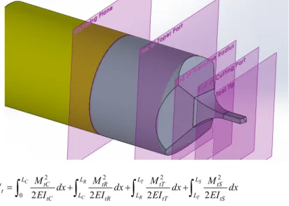
Since for micro end mills the axial stiffness is much larger than radial stiffness, therefore, it is assumed that the bulk deflection of the micro end mills are mainly due to the radial component of the machining forces, therefore deflection due to axial forces are neglected (Dow et al., 2004; Kim et al., 2003). In order to use Castigliano’s second theorem, the tool is modelled as a cantilever beam with variable cross-sectional area. To determine cross-sectional characteristics, the micro end mill is partitioned into four sections as illustrated in Figure 2. The following terminology is used during formulations:
The subscript ‘t’ is used for tangential direction and the subscript ‘r’ is used for radial direction. The subscript ‘C’ is used for cutting portion of the tool which has a length of ‘LC’ and extends from tool tip to the plane shown as ‘end of cutting part’ in Figure 2. The
subscript ‘R’ stands for the part with transition radius having a length of ‘LR’ between the
end of ‘cutting plane’ and end of ‘transition radius plane’. Using the above mentioned notation, the energy stored in the micro end mill as a result of different components of the machining forces (Fr: radial force and Ft: tangential force) can be expressed as:
Figure 2 Tool partitioning for deflection calculations (see online version for colours)
2 2 2 2 0 2 2 2 2 C R T S C R T L L L L tC tR tT tS t L L L tC tR tT tS M M M M U dx dx dx dx EI EI EI EI =
∫
+∫
+∫
+∫
2 2 2 2 0 2 2 2 2 c r t s c r t L L L L Rc Rr Rt Rs R L L L Rc Rr Rt Rs M M M M U dx dx dx dx EI EI EI EI =
∫
+∫
+∫
+∫
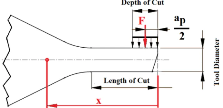
(2)Assuming a uniform distribution of the forces over the engagement depth (depth of cut (ap)), the distributed uniform force can be replaced by a concentrated force acting in a position of ‘ap/2’ from tool tip, as depicted in Figure 3.
Figure 3 Concentrated force applied to a position of ‘ap/2’ from tool tip (see online version for colours)
Therefore at any point at a distance ‘x’ from tool tip, the moment can be written as: ( )
2
p
a
M x =F x⎛⎜⎝ − ⎞⎟⎠ (3)
Since there is no other external force acting on the micro end mill, we have:
2 p tC tR tT tS t a M =M =M =M =F⋅⎛⎜⎝x− ⎞⎟⎠ (4) 2 p rC rR rT rS r a M =M =M =M =F ⋅⎛⎜⎝x− ⎞⎟⎠
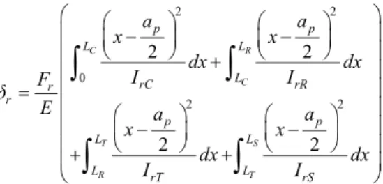
Substituting equation (4) into equation (2) and applying equation (1), the end deflections in tangential and radial directions can be written as:
2 2 0 2 2 2 2 2 2 C R C T S R T p p L L L tC tR t t p p L L L tT L tS a a x x dx dx I I F δ E a a x x dx dx I I ⎛ ⎛ ⎞ ⎛ ⎞ ⎞ ⎜ ⎜ − ⎟ ⎜ − ⎟ ⎟ ⎜ ⎝ ⎠ + ⎝ ⎠ ⎟ ⎜ ⎟ ⎜ ⎟ = ⎜ ⎛ ⎞ ⎛ ⎞ ⎟ ⎜ ⎜⎝ − ⎟⎠ ⎜⎝ − ⎟⎠ ⎟ ⎜+ + ⎟ ⎜ ⎟ ⎝ ⎠
∫
∫
∫
∫
(5)2 2 0 2 2 2 2 2 2 C R C T S R T p p L L L rC rR r r p p L L L rT L rS a a x x dx dx I I F δ E a a x x dx dx I I ⎛ ⎛ ⎞ ⎛ ⎞ ⎞ ⎜ ⎜ − ⎟ ⎜ − ⎟ ⎟ ⎜ ⎝ ⎠ + ⎝ ⎠ ⎟ ⎜ ⎟ ⎜ ⎟ = ⎜ ⎛ ⎞ ⎛ ⎞ ⎟ ⎜ ⎜⎝ − ⎟⎠ ⎜⎝ − ⎟⎠ ⎟ ⎜+ + ⎟ ⎜ ⎟ ⎝ ⎠
∫
∫
∫
∫
In order to calculate the deflection components, it is necessary to determine the moment of inertia of each portion of the micro end mill depicted in Figure 2. The moment of inertia for each section is calculated in Table 1.
Table 1 The moment of inertia for different cross-sections of the micro end mill
4 96 C rC D I =
(
)
4 2 4 tan ( ) 96 C tC D I = + α 3 3 1 ( ) ( ) ( )cos ( ) 12 rR Tr Tr I x = a x b x α(
2 2 2)
( ) 1 ( ) ( )cos( ) ( ) ( )sin ( ) 12 tR Tr Tr Tr Tr I x a x b x b x a x ⎡ ⎤ = ⎣ α + α ⎦ 2 ( ) cos( ) 2 1 1 2 c Tr Tr Tr D x a x R R ⎛ ⎛ ⎞ ⎞ ⎜ ⎟ = + ⎜ − − ⎜ ⎟ ⎟ ⎝ ⎠ ⎝ ⎠ α 2 ( ) 2 1 1 Tr c Tr Tr x b x D R R ⎛ ⎛ ⎞ ⎞ ⎜ ⎟ = + ⎜ − − ⎜ ⎟ ⎟ ⎝ ⎠ ⎝ ⎠ 3 3 1 ( ) ( ) ( )cos ( ) 12 rT T T I x = a x b x α(
2 2 2)
1 ( ) ( ) ( )cos( ) ( ) ( )sin ( ) 12 tT T T T T I x = ⎡⎣a x b x α b x +a x α ⎤⎦(
)
( ) cos( ) 2 1 cos( ) 2 tan( ) 2 c T Tr D a x =⎛⎜⎝ α + R − γ ⎞⎟⎠+ x γ
(
)
(
)
( ) 2 1 cos( ) 2 tan( ) T c Tr b x = D + R − γ + x γ ( )4 64 S rS tS π D I =I =By substituting calculated moment of inertias into equation (5), the tangential and radial deflections of tailored micro end mill can be calculated as:
(
) (
)
(
)
3 2 4 3 2 4 2 2 2 2 2 3 96 2 2 3 64 2 2 3 2 2 1 1 12 cos( ) 2 1 1 2 cos ( ) r p p c C r C r C p p S T S T r S T S p C Tr Tr C r Tr T a a L L F L δ πED a a L L L L F L L πED a x x D R R D x F R R E ⎛⎛ ⎞⎛ ⎞ ⎞ − + ⎜⎜⎝ ⎟⎜⎠⎝ ⎟⎠ ⎟ ⎝ ⎠ = ⎛⎛ ⎞⎛ − ⎞ − ⎞ ⎜⎜ ⎟⎜ − − ⎟+ ⎟ ⎜⎝ ⎠⎝ ⎠ ⎟ ⎝ ⎠ + ⎛ ⎞ − ⎜ ⎟ ⎝ ⎠ ⎛ ⎛ ⎞⎞ ⎜ − ⎜⎜ − − ⎟⎟⎟ ⎜ ⎝ ⎠⎟ ⎝ ⎠ ⎛ ⎛ ⎞⎞ ⎜ − ⎜ − − ⎟⎟ + ⎜ ⎜ ⎟ ⎝ ⎠ ⎝ ⎠ α α(
)
(
)
(
)
3 2 3 2cos( ) 2 1 cos( ) 2 tan( )
2 2 1 cos( ) 2 tan( ) R C T R L L p L L C Tr C Tr dx a x D R γ x γ D R γ x γ ⎛ ⎞ ⎜ ⎟ ⎜ ⎟ ⎜ ⎟ ⎜ ⎟ ⎜ ⎟ ⎜ ⎟ ⎜ ⎟ ⎜ ⎟ ⎜ ⎟ ⎟ ⎜ ⎟ ⎜ ⎟ ⎜ ⎛ ⎞ ⎟ − ⎜ ⎜⎝ ⎟⎠ ⎟ ⎜+ ⎟ ⎜ ⎛ ⎞ ⎟ ⎜ ⎜ + − + ⎟ ⎟ ⎝ ⎠ ⎜ ⎟ ⎜ + − + ⎟ ⎝ ⎠
∫
∫
α (6)(
)
(
) (
)
(
)
3 2 4 2 3 2 4 2 2 2 2 2 2 3 96 2 2 3 4 tan ( ) 64 2 2 3 2 2 1 1 12 cos( ) 2 1 1 2 sin ( ) cos ( ) p p C C t C t C p p S T S T t S T S p C Tr Tr C t Tr Tr a a L L F L δ ED a a L L L L F L L πED a x x D R R D x F R R E ⎛⎛ ⎞⎛ ⎞ ⎞ − + ⎜⎜⎝ ⎟⎜⎠⎝ ⎟⎠ ⎟ ⎝ ⎠ = + ⎛⎛ ⎞⎛ − ⎞ − ⎞ ⎜⎜ ⎟⎜ − − ⎟+ ⎟ ⎜⎝ ⎠⎝ ⎠ ⎟ ⎝ ⎠ + ⎛ ⎞ − ⎜ ⎟ ⎝ ⎠ ⎛ ⎛ ⎞⎞ ⎜ − ⎜⎜ − − ⎟⎟⎟ ⎜ ⎝ ⎠⎟ ⎝ ⎠ − − − + α α α α(
)
(
)
(
)
3 2 3 3 2cos( ) 2 1 cos( ) 2 tan( )
2 2 1 cos( ) 2 tan( ) R C T R L L p L L C Tr C Tr dx a x D R γ x γ D R γ x γ ⎛ ⎞ ⎜ ⎟ ⎜ ⎟ ⎜ ⎟ ⎜ ⎟ ⎜ ⎟ ⎜ ⎟ ⎜ ⎛ ⎞ ⎟ ⎛ ⎞ ⎜ ⎜ ⎟ ⎟ ⎜ ⎟ ⎜ ⎜ ⎜ ⎟⎟ ⎟ ⎜ ⎝ ⎝ ⎠⎠ ⎟ ⎜ ⎟ ⎜ ⎛ ⎞ ⎟ − ⎜ ⎟ ⎜ ⎝ ⎠ ⎟ ⎜+ ⎟ ⎜ ⎛ ⎞ ⎟ + − + ⎜ ⎜⎝ ⎟⎠ ⎟ ⎜ ⎟ ⎜ + − + ⎟ ⎝ ⎠
∫
∫
α (7)It should be mentioned that due to the complex form of the integrals, closed form solution cannot be obtained. Therefore, the integrals are obtained numerically based on adaptive Gauss-Kronrod quadrature method. The total deflection is calculated as:
2 2
total t r
δ = δ +δ (8)
3.2 Finite element modelling of deflections and stresses
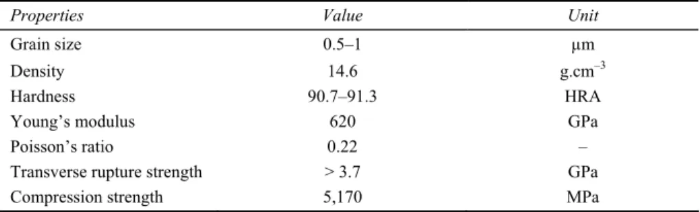
While analytical models are suitable in the calculation of micro end mill deflections and can be integrated into cutting force models, their use is limited in calculating stresses and prediction of failure, therefore finite element (FE) modelling is used to predict micro tool deflection and stresses. To conduct FE simulations, parametric solid model of the tools has been created in SolidWorks platform and is live-linked into COMSOL Multiphysics to conduct finite element simulations. Material properties for this study are determined based on energy-dispersive x-ray spectroscopy (EDS) of the (WC-Co) material (Oliaei and Karpat, 2017). WC-Co material of the micro end mills is 90WC-10Co with a grain size of (0.5–1 µm). The properties of this cutting tool material are given in Table 2. The values given in Table 2 are taken from Fang (2005) and Upadhyaya (1998). The developed finite element model is used to predict tool failure using transverse rupture strength (TRS) as failure criterion. A TRSof (TRS > 3.7 GPa) is considered for ultra-fine grain tungsten carbide material (Fang, 2005; Oliaei and Karpat, 2015) and is used as tool failure criterion. Tetrahedral elements are used to mesh the model. Figure 4 illustrates the finite element model of the single edge micro end mill with RTr = 1.8 mm, LC = 0.8 mm.
Complete mesh of the model consists of 18,676 domain elements, 3,514 boundary elements and 398 edge elements. A fixed constraint has been applied into the clamping region shown in Figure 4.
Table 2 Material properties of 90WC-10Co
Properties Value Unit
Grain size 0.5–1 µm
Density 14.6 g.cm–3
Hardness 90.7–91.3 HRA
Young’s modulus 620 GPa
Poisson’s ratio 0.22 –
Transverse rupture strength > 3.7 GPa
Compression strength 5,170 MPa
4 Experimental analysis of tool deflections
4.1 Experimental identification of tool breakage during micro milling
A series of micro milling experiments are conducted on Ti6Al4V workpiece at a spindle speed of 25,000 RPM and a depth of cut of 100 µm. In these tests, the feed rate is increased gradually in a stepwise manner until tool breakage occurred. In each step, the feed per tooth has been increased by 1 µm/tooth and cutting forces are recorded. Figure 5 illustrates the recorded cutting forces at the point of failure. At feed per tooth value of 18 µm/tooth, peak cutting forces were recorded about 18 (N) and 17 (N) in X and Y directions, respectively.
Figure 5 Cutting force data at the point of failure (see online version for colours)
Figure 6 Experimental setup for static tool deflection measurement (see online version for colours)
Figure 7 Micro tool deflections at the point of failure measured by capacitive sensor (see online version for colours)
4.2 Static tool deflection tests
A static tool deflection measurement setup is designed to measure the deflection of micro end mills. An experimental setup which uses a single plate capacitive sensor (PI-D-510.101) with nanometre level resolution has been used (Figure 6). The micro end mill is mounted on a self-developed indexing device attached to the Z axis of the micromachining centre (Mikrotool DT-110) with the same overhang used in micromilling experiments. The use of an indexing device makes it possible to lock the tool to avoid its rotation and to apply the force at desired angles. A rigid tungsten carbide block is mounted on a table-top mini-dynamometer (Kistler-9256C1). The static force is applied by pushing the micro end mill against block. The static force induced deflection is measured using a probe attached to the capacitive sensor. Very small step-sizes are used at low feed rates when pushing the tool against the block. The induced deflections are recorded by a data acquisition system attached to a PC. The force profile of the micro milling test is applied to the tool and the displacement of the tool tip were recorded. The measurement results, shown in Figure 6, indicate a tool deflection of 25 μm at the given force profile.
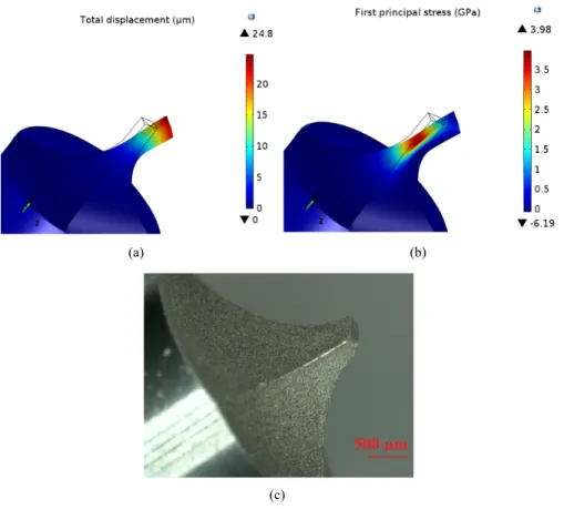
Figure 8 FEM results of tailored micro end mill (a) deflection (b) first principal stress (c) broken micro end mill (see online version for colours)
(a) (b)
4.3 Validation of the FE and analytical deflection models
The recorded force data have been used as input to the FE model and tool deflection and stresses are calculated. The results of finite element model can be seen in Figures 8(a) and 8(b). A broken micro end mill is also shown in Figure 8(c) for comparison. It can be seen that using finite element method, the developed stress can be estimated with 7.5% error assuming that tool rupture strength is 3.7 GPa, however since finite element predictions give a larger stress values, this can be considered as an additional factor of safety at the early stage of the micro end mill design.
A comparison is made between finite element predictions and the developed analytical model to compare the results of these models in predicting deflections in tailored micro end mills. To do so the deflection of a micro end mill with the specifications given in Table 3 is considered.
Table 3 Micro end mill geometric specifications
Parameter Value Parameter Value
Neck taper angle (deg.) 60 Clearance angle (deg.) 14 Transition radius (mm) 1.5 Overhang length (mm) 7.7 Length of cut (mm) 0.8 Shank diameter (mm) 4
Tip diameter (mm) 0.4 Depth of cut (mm) 0.05
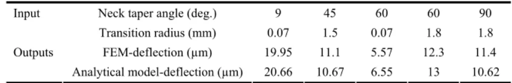
Table 4 A comparison between FEM and analytical model for different NA and RTr values
Neck taper angle (deg.) 9 45 60 60 90 Input
Transition radius (mm) 0.07 1.5 0.07 1.8 1.8 FEM-deflection (µm) 19.95 11.1 5.57 12.3 11.4 Outputs
Analytical model-deflection (µm) 20.66 10.67 6.55 13 10.62
Figure 9 Calculated deflection for a cutting tool with specifications given in Table 3 (see online version for colours)
In order to make comparison, a micro end mill with the specifications given in Table 3 is modelled in COMSOL Multiphysics and tool deflection is obtained for a sample force of 8N in both directions. Figure 8 illustrates the deflection obtained by COMSOL Multiphysics. Under similar loading condition and geometric parameters, a comparison is
also made for different combinations of neck taper angle and transition radius. The results are shown in Table 4. Results obtained from analytical and finite element were found to be in close agreement.
5 Optimisation of tailored micro-end mills based on FEM
5.1 Graphical method
Design optimisation of tailored micro end mills can be performed by using the finite element model. Neck taper angle and transition radius are considered as design parameters and the response of the micro end mills with various geometries are obtained for the forces at the point of failure. A safety factor of 1.25 is considered in terms of cutting forces, assuming that cutting forces for practical cutting conditions will be 25% lower than that of forces obtained at the point of failure. Using finite element analysis, maximum deflection and maximum first principal stresses are obtained for the full factorial combinations of neck taper angle (NA) (9°, 15°, 20°, 30°, 45°, 60°, 70°, 80° and 90°) and transition radius (RTr) (0.07, 0.15, 0.25, 0.5, 0.75, 1, 1.25, 1.5 and 1.8) mm. The
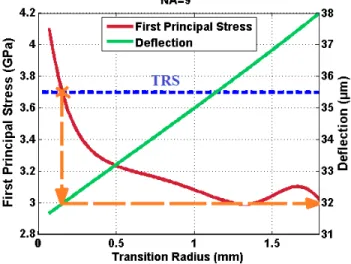
length of cut has kept constant (0.8 mm). Total numbers of 81 finite element simulations are performed. For each neck taper angle, first principal stress and deflection curves are plotted as a function of transition radius. Figure 10 illustrates the results for neck taper angle of 9°. As it can be seen in Figure 10, for each neck taper angle, the transition radius at which first principal stresses are equal to the TRS of the material will be obtained, afterwards the corresponding deflection is determined.
Figure 10 Calculation of critical transition radius and corresponding deflection (see online version for colours)
In a similar way shown in Figure 10, for each neck taper angle a critical transition radius is obtained by finding the transition radius at point of failure, where first principle stress is equal to the TRS of the cutting tool material. Critical transition radii and corresponding
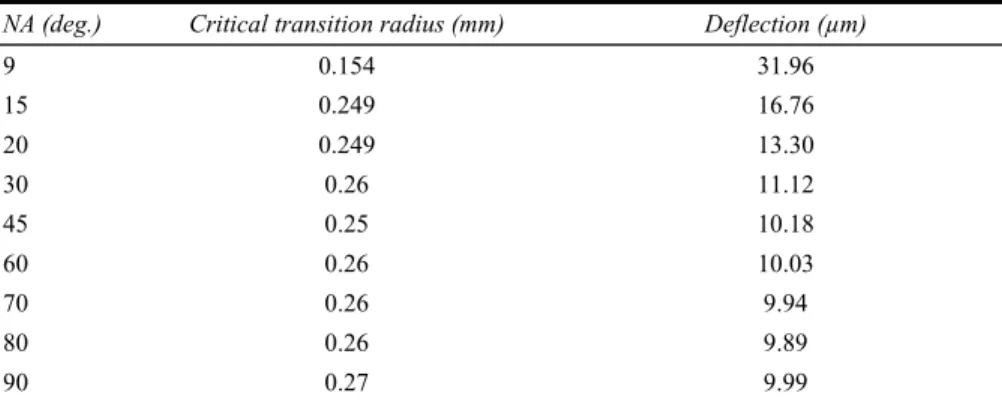
deflections are given in Table 5. It can be seen from Table 5 that a tool with lowest deflection should have a neck taper angle between 60° and 80° with a transition radius around 0.26 mm.
Table 5 Critical transition radius and corresponding deflections for different neck taper angles NA (deg.) Critical transition radius (mm) Deflection (µm)
9 0.154 31.96 15 0.249 16.76 20 0.249 13.30 30 0.26 11.12 45 0.25 10.18 60 0.26 10.03 70 0.26 9.94 80 0.26 9.89 90 0.27 9.99
5.2 Nonlinear optimisation method
Beside graphical optimisation, analytical optimisation of tailored micro end mill geometry can also be done by expressing deflections and stresses as a function of design parameters, i.e., transition radius and neck taper angle. This can be done by fitting a surface to the data obtained in previous section through finite element simulations. Figure 11(a) and Figure 11(b) illustrate the surfaces fitted to express the variation of tool deflection and first principal stresses as a function of neck taper angle and transition radius, respectively. The goodness of fit is decided based on R2 values greater than 0.985.
Figure 11 Variation of (a) deflection (b) first principal stress as a function RTr and γ (see online
version for colours)
The equation of tool deflection as a function of neck taper angle and transition radius expressed as in equation (9):
(
)
(
)
(
(
)
)
2 2 3 2 00 10 01 20 11 02 30 21 2 3 4 3 2 2 3 4 12 03 40 31 22 13 04 5 4 3 2 2 3 4 5 50 41 32 23 14 05 2 , sin exp Tr Tr Tr Tr Tr Tr Tr Tr Tr Tr Tr Tr Tr Tr Tr Tr Tr Tr def γ R p p γ p R p γ p γR p R p γ p γ R p γR p R p γ p γ R p γ R p γR p R p γ p γ R p γ R p γ R p γR p R b mπγR c wR = + + + + + + + + + + + + + + + + + + + + + + − (9)For simplicity in the representation, the neck taper angle is denoted by γ. The coefficients in equation (9) are given in Table 6.
Table 6 Coefficients of equation (9)
Coefficient p00 p01 p02 p03 p04 p05
Value 74.317 7.889 –3.704 3.303 –2.992 0.9174
Coefficient p10 p11 p12 p13 p14 p20
Value –7.688 0.4719 –0.2701 0.1209 –0.02289 0.3223
Coefficient p21 p22 p23 p30 p31 p32
Value –0.008221 0.001606 –0.0001821 –0.006389 7.865e-5 –5.677e-6
Coefficient p40 p41 p50 w b c,(m)
Value 5.99e-5 –2.979e-7 –2.138e-7 2.889 0.1585 3.42, (0.07748) In a similar way, the equation for first principal stress can be written as follows with coefficients given in Table 7.
(
)
2 2 3 00 10 01 20 11 02 30 2 2 3 4 3 21 12 03 40 31 2 2 3 4 4 3 2 22 13 04 41 32 2 3 4 5 23 14 05 1 P.S ,st Tr Tr Tr Tr Tr Tr Tr Tr Tr Tr Tr Tr Tr Tr Tr Tr γ R q q γ q R q γ q γR q R q γ q γ R q γR q R q γ q γ R q γ R q γR q R q γ R q γ R q γ R q γR q R = + + + + + + + + + + + + + + + + + + + (10)Table 7 Coefficients of equation (10)
Coefficient q00 q01 q02 q03 q04 q05 q10
Value 3.855 –11.91 38.6 –49.72 27.84 –5.651 0.1808
Coefficient q11 q12 q13 q14 q20 q21 q22
Value –0.4385 0.4101 –0.1733 0.02775 –0.00391 0.006036 –0.003101
Coefficient q23 q30 q31 q32 q40 q41
Value 0.0005435 3.785e-5 –3.853e-5 8.587e-6 –1.359e-7 9.305e-8 The optimisation problem can be formulated as follows based on the deflection and first principal stresses as a function of neck taper angle and transition radius:
(
)
(
)
Tr st Tr Tr minimise def , R subject to:1 PS , R 3.7 where 9 90 0.07 R 1.8 γ γ γ < < < < <The optimisation problem has been solved using MATLAB software, where the deflection function is minimised under the constraint of (Induced stress < TRS). The optimum neck taper angle is obtained as 68° with a transition radius of 0.24 mm. The corresponding deflection is obtained as 8.9 µm. WEDM process has been used to fabricate tailored micro end mill with optimum parameters. The fabricated micro end mill is shown in Figure 12.
Figure 12 Fabricated tailored micro end mill with optimum design parameters (see online version for colours)
The static tool deflection measurements depicted in Figure 13 shows that the deflection of the micro end mill has substantially been reduced by optimising design parameters. Upon verifying the efficiency and reliability of the finite element model in predicting tool deflection and failure, graphical and analytical optimisation is used to determine optimum tool design parameters to minimise tool deflections.
Figure 13 Deflection of a micro tool with optimum geometry at the point of failure measured by capacitive sensor (see online version for colours)
6 Conclusions
In this study, a design methodology has been proposed for a tailored single edge micro end mills. The static tool deflections are measured using a dedicated setup which uses capacitive sensors with a very high accuracy. Beside experimental setup, analytical and finite element models of the tailored single edge micro end mills are developed and successfully used for the prediction of micro end mill deflection. A good agreement between finite element simulations, analytical model and experimental tests are observed. It has also shown that, the finite element method can be used for tool failure predictions at the initial steps of cutting tool design process. The conclusions of this work can be summarised as follows:
• A good agreement between finite element simulations and proposed analytical model predictions has been observed in determining deflections of tailored micro end mills. • A finite element based design optimisation methodology of tailored micro end mills
is proposed. Using this optimisation methodology optimum values of neck taper angle and transition radius are determined based on minimum tool deflection criterion. For the geometry under consideration, a neck taper angle of 68° with a transition radius of 0.24 mm resulted in a minimum deflection of 8.9 µm.
Acknowledgements
The authors would like to acknowledge the Scientific and Technological Research Council of Turkey (TUBITAK) for financial support of this work through project 110M660. The authors would also like to thank the Ministry of Development of Turkey (HAMIT-Micro System Design and Manufacturing Research Centre).
References
Biermann, D, Krebs, E., Sacharow, A. and Kersting, P. (2012) ‘Using NC-path deformation for compensating tool deflections in micro milling of hardened steel’, Procedia CIRP, Vol. 1, pp.132–137.
Cheng, X., Wang, Z., Nakamoto, K. and Yamazaki, K. (2010) ‘Design and development of PCD micro straight edge end mills for micro/nano machining of hard and brittle materials’, Journal of Mechanical Science and Technology, Vol. 24, No. 11, pp.2261–2268.
Dow, T.A., Miller, E.L. and Garrard, K. (2004) ‘Tool force and deflection compensation for small milling tools’, Precision Engineering, Vol. 28, No. 1, pp.31–45.
Fang, Z.Z. (2005) ‘Correlation of transverse rupture strength of WC-Co with hardness’, International Journal of Refractory Metals and Hard Materials, Vol. 23, No. 2, pp.119–27. Feng, H-Y. and Menq, C-H. (1996) ‘A flexible ball-end milling system model for cutting force and
machining error prediction’, Transactions-American Society of Mechanical Engineers Journal of Manufacturing Science and Engineering, Vol. 118, No. 4, pp.461–69.
Kim, C-J., Mayor, J.R. and Ni, J. (2004) ‘A static model of chip formation in microscale milling’, Transactions of the ASME-B-Journal of Manufacturing Science and Engineering, Vol. 126, No. 4, pp.710–718.
Kim, G.M., Kim, B.H. and Chu, C.N. (2003) ‘Estimation of cutter deflection and form error in ball-end milling processes’, International Journal of Machine Tools and Manufacture, Vol. 43, No. 9, pp.917–924.
Kirsch, B., Bohley, M., Arrabiyeh, P.A. and Aurich, J.C. (2017) ‘Application of ultra-small micro grinding and micro milling tools: possibilities and limitations’, Micromachines, Vol. 8, No. 9, p.261.
Kline, W.A., DeVor, R.E. and Shareef, I.A. (1982) ‘The prediction of surface accuracy in end milling’, Journal of Engineering for Industry, Vol. 104, No. 3, pp.272–78.
Mijušković, G., Krajnik, P. and Kopač, J. (2015) ‘Analysis of tool deflection in micro milling of graphite electrodes’, The International Journal of Advanced Manufacturing Technology, Vol. 76, Nos. 1–4, pp.209–17.
Oliaei, S.N.B. and Karpat, Y. (2015) ‘Influence of tool wear on machining forces and tool deflections during micro milling’, Int. J. Adv. Manuf. Technol., Vol. 84, pp.1963–1980. Oliaei, S.N.B. and Karpat, Y. (2017) ‘Built-up edge effects on process outputs of titanium alloy
micro milling’, Precision Engineering, Vol. 49, pp.305–315.
Reichenbach, I.G., Fallenstein, F. and Aurich, J.C. (2014) ‘CAE analysis of single-edge micro end mills-methodology and results’, ICOMM, No. 33.
Rodríguez, P. and Labarga, J.E. (2015) ‘Tool deflection model for micromilling processes’, The International Journal of Advanced Manufacturing Technology, Vol. 76, Nos. 1–4, pp.199–207.
Schaller, T., Bohn, L., Mayer, J. and Schubert, K. (1999) ‘Microstructure grooves with a width of less than 50 μm cut with ground hard metal micro end mills’, Precision Engineering, Vol. 23, No. 4, pp.229–235.
Upadhyaya, G.S. (1998) Cemented Tungsten Carbides: Production, Properties and Testing, William Andrew, Noyes Publications, USA.
Uriarte, L., Herrero, A., Zatarain, M., Santiso, G., Lopez de Lacalle, L.N., Lamikiz, A. and Albizuri, J. (2007) ‘Error budget and stiffness chain assessment in a micromilling machine equipped with tools less than 0.3 mm in diameter’, Precision Engineering, Vol. 31, No. 1, pp.1–12.