Research Article
Flexible Numerology in 5G NR: Interference Quantification and
Proper Selection Depending on the Scenario
Josue Flores de Valgas ,
1Jose F. Monserrat ,
1and H¨useyin Arslan
2 1Universitat Polit`ecnica de Val`encia, iTEAM Research Institute, Camino de Vera s/n, 46022 Valencia, Spain 2Department of Electrical and Electronics Engineering, Istanbul Medipol University, Istanbul 34810, Turkey Correspondence should be addressed to Josue Flores de Valgas; jofl[email protected]Received 15 October 2020; Revised 1 February 2021; Accepted 1 March 2021; Published 10 March 2021 Academic Editor: Massimo Condoluci
Copyright © 2021 Josue Flores de Valgas et al. This is an open access article distributed under the Creative Commons Attribution License, which permits unrestricted use, distribution, and reproduction in any medium, provided the original work is properly cited.
The 3rd Generation Partnership Project (3GPP) adopted cyclic prefix OFDM (CP-OFDM) for both uplink and downlink commu-nications (although DFT-s-OFDM is also allowed in the uplink) in 5G New Radio (NR) Release 15. However, due to the variety of proposed deployment options and scenarios, a single numerology will not be enough to fulfil all performance requirements. A scalable OFDM numerology was required to enable diverse services on a wide range of frequencies and deployments, and finding the right numerology for each scenario is of special relevance for the proper functioning of 5G NR. Using a simulator calibrated according to the parameters established for NR performance by the 3GPP, this paper presents the performance evaluation of NR for the main 5G scenarios and different CP-OFDM numerologies and device speeds. Results show that increasing subcarrier spacing boosts the strength of the system against intercarrier interference (ICI) caused my Doppler spread; however, to increase subcarrier spacing, the CP must be reduced proportionally, which makes intersymbol interference (ISI) and ICI caused by insufficient CP have a more predominant effect. Therefore, it is necessary to quantify the total interference of the system, in order to determine the proper numerology for each scenario, which will depend on all the factors mentioned above, and not only on the operation band, as suggested in the standardization process. All this allows concluding that the choice of the appropriate numerology for a particular system depends not only on the band of operation but also on the deployment scenario and the speed of the user equipment (UE). Likewise, it is concluded that it is even possible to use more than one numerology for the same scenario.
1. Introduction
Since the beginning of 2016, the 3rd Generation Partnership Project (3GPP) has been working on the standardization of 5G New Radio (NR) [1], a new Radio Access Technology (RAT) that will guarantee the performance, interoperability, and quality of 5G devices and networks, within next-gen-eration global standard [2]. This will allow services such as virtual reality, augmented reality, automated intelligence, autonomous vehicles, and the Internet of Things (IoT) [3] to become a reality. In order to provide the aforementioned services, a new generation of mobile communication sys-tems will be necessary since these are based on more reliable, more prompt, and even faster interconnectivity.
To meet all this variety of services, which 5G standard is designed to satisfy, there are three main challenges that 5G
NR must solve in order to enable a truly networked society: a higher data rate, more reliable and low latency transmis-sions, and a massive growth in the number of devices. These challenges result in three broad use cases [4]: enhanced mobile broadband (eMBB), which requires very high data rates and large bandwidths, e.g., highly mobile UE connected to macrocells; ultra-reliable low-latency communications (uRLLC), which require very high reliability and availability, as very low latency, e.g., power system automation and factory process; and massive machine type communications (mMTC), which require low energy consumption at the UE, high connection density, and low bandwidth, e.g., collection of the measurements from a massive number of sensors.
Several candidate waveforms were submitted to the 5G NR standardization process, many of which had been under study even before the formal beginning of this new
Volume 2021, Article ID 6651326, 9 pages https://doi.org/10.1155/2021/6651326
specification [5–7]. Most of these candidates are multicarrier waveforms, like the well-known cyclic prefix OFDM (CP-OFDM), universally filtered OFDM (also known as universal filtered multicarrier (UFMC)), pulse shaped OFDM (P-OFDM), windowed OFDM (W-(P-OFDM), and filter-bank multicarrier (FBMC). Nevertheless, after multiple discus-sions and a long evaluation process, in August 2016, the 3GPP decided to utilize CP-OFDM for both downlink and uplink in NR Release 15. Being built over OFDM (which is used on LTE) gives 5G NR an advantage since it allows the devices to keep low complexity and hence low hardware costs. However, a single OFDM numerology, i.e., subcarrier spacing and cyclic prefix length, cannot satisfy the perfor-mance constraints across the desired frequency range and all proposed deployment options and scenarios. This is why the OFDM numerology must be adapted to fit the specific re-quirements of services, operation frequencies, and deploy-ment scenarios.
This paper provides an in-depth analysis of the use of 5G numerologies within the main 5G scenarios, using TDL-C channel model and taking into account the operating fre-quency and the mobility of the UE. Although there are some studies regarding OFDM numerology itself [8, 9] and some other approaches considering the use of multiple numer-ologies at the same time, looking for the lowest inter-numerology interference (INI) [10–12], there is currently no evaluation of the impact of numerology changes on the total system interference, making possible to determine whether a numerology is appropriate for a particular 5G scenario. This paper’s main contribution is to demonstrate that it is pos-sible to use more than a single 5G OFDM numerology for every proposed band throughout the 5G spectrum. In order to determine which numerology is better suitable for each scenario, the total interference of the system was calculated for all possible scenarios, taking into account the topology, operating frequency, and mobility, allowing to determine which numerology is better fitted for each scenario. The remaining sections of the paper are structured as follows. Section 2 describes the analysis of interference calculation, while Section 3 provides an explanation of the 5G OFDM numerologies. Section 4 presents the performance results. Finally, Section 5 draws the main conclusions of this work.
2. ICI and ISI Analysis
In an OFDM system, the transmitted data are mapped to some constellation points in order to obtain data symbols. The transmitter then applies an N-point inverse discrete Fourier transform (IDFT), with the purpose of obtaining the time-domain OFDM symbols. The time-domain OFDM n-th block x[n] � [xn,0, xn,1, · · · , xn,N−1]is given by
x[n] � FHNS[n], (1) where FH
Nis the N-point IDFT matrix, S[n] � [sn,0, sn,1, · · · ,
sn,N−1] is the transmitted symbol, and N is the block size. After the IDFT block, the cyclic prefix (CP) is added, which is a copy of the last M samples of the IDFT output. The main function of the CP is to avoid the overlapping between
consecutive OFDM symbols, but it also turns the linear convolution by the channel into circular, thus allowing to use frequency-domain subcarrier-wise equalizer. In the receiver side, the CP is discarded, and then an N-point FFT is applied. In the absence of noise, the n-th received block
X[n] � [ Xn,0, Xn,1, · · · , Xn,N−1]is
X[n] � H[n]x[n], (2) where H[n] is the time-domain channel matrix, formed by the elements of the channel impulse response during the n-th block interval. This OFDM structure can be affected by several external aspects, which trigger harmful effects on the system’s performance by modifying the structure in a dis-ruptive manner; this is what is known as interference. In the case of a scenario with insufficient CP, the system is affected by intersymbol interference (ISI) and intercarrier interfer-ence (ICI), whereas in a scenario with a high Doppler spread, the system is also affected by ICI.
2.1. Insufficient Cyclic Prefix. In the presence of a multipath
channel, what happens is that at the receiver side, all the multipath components are summed. As a result, we have multiple echoes of each symbol arriving at multiple instances of time and overlapping with each other, causing data to get corrupted and consequently lost. The total delay between the first echo of the symbol and the last one can be measured through the delay spread (DS) concept. Therefore, most of the energy caused by the distortion in the symbol reaches up to certain DS given by the characteristic of the channel.
If the DS is longer than the CP (DS > CP), then the echoes will arrive during the core OFDM symbol, and there will be a certain percentage of interference in the signal. Therefore, by extending the CP length in such a way that it is longer than the DS (CP > DS), the overlap will happen only during the CP, which is discarded at the receiver, and hence there will not be interference due to the DS.
One of the main benefits of using a CP between con-secutive OFDM symbols is that it isolates them from each other, acting as a guard interval to protect the OFDM signal from ISI. However, there are cases where the CP can be shorter than the DS, which causes ISI because of the overlapping of subsequent symbols. On the other hand, a shorter OFDM symbol period makes subcarriers more separated from each other, which at the end is good to combat ICI. There is a compromise between counteracting the effects of ISI and suffering from more effects of ICI. This can be introduced by extending the model in equation (2). Considering a channel with an impulse response of length L and a CP of length M, if L > M, then the n-th received block now would be [13]
X[n] � H[n]x[n] + X1[n] + X2[n], (3) where X1[n] � BX(i−1) and X
2[n] � −AX(i); X(i−1) is the
previous transmitted symbol; X(i)is the current transmitted
symbol; B is the N × N contribution of the elements of the channel impulse response that exceeds the CP, as seen in equation (5); and A is the same matrix as B but with
circularly shifted L − M columns to the left, as seen in the following equation: A � 0 · · · hM hM−1 · · · hL+1 0 · · · 0 0 · · · 0 hM · · · hL+2 0 · · · 0 ⋮ · · · ⋮ ⋱ ⋱ ⋮ ⋮ ⋮ ⋮ 0 · · · 0 0 ⋱ hM 0 · · · 0 ⋮ · · · ⋮ ⋱ ⋱ ⋮ ⋮ ⋮ ⋮ 0 · · · 0 0 · · · 0 0 · · · 0 ⎡ ⎢ ⎢ ⎢ ⎢ ⎢ ⎢ ⎢ ⎢ ⎢ ⎢ ⎢ ⎢ ⎢ ⎢ ⎢ ⎢ ⎢ ⎢ ⎢ ⎢ ⎢ ⎢ ⎢ ⎢ ⎢ ⎢ ⎢ ⎢ ⎢ ⎢ ⎢ ⎢ ⎢ ⎢ ⎢ ⎢ ⎢ ⎢ ⎢ ⎢ ⎢ ⎢ ⎢ ⎢ ⎢ ⎢ ⎢ ⎢ ⎢ ⎢ ⎢ ⎢ ⎢ ⎢ ⎢ ⎢ ⎢ ⎢ ⎢ ⎢ ⎣ ⎤⎥⎥⎥⎥⎥⎥⎥⎥⎥ ⎥⎥⎥⎥⎥⎥⎥⎥ ⎥⎥⎥⎥⎥⎥⎥⎥ ⎥⎥⎥⎥⎥⎥⎥⎥ ⎥⎥⎥⎥⎥⎥⎥⎥ ⎥⎥⎥⎥⎥⎥⎥⎥ ⎥⎥⎥⎥⎥⎥⎥⎥ ⎥⎥⎥⎦ , (4) B � 0 · · · 0 · · · hM · · · · · · hL+1 0 · · · 0 · · · 0 hM · · · hL+2 ⋮ · · · ⋮ ⋱ ⋱ ⋮ ⋮ ⋮ 0 · · · 0 ⋱ ⋱ 0 · · · hM ⋮ · · · ⋮ ⋱ ⋱ ⋮ ⋮ ⋮ 0 · · · 0 · · · 0 · · · 0 ⎡ ⎢ ⎢ ⎢ ⎢ ⎢ ⎢ ⎢ ⎢ ⎢ ⎢ ⎢ ⎢ ⎢ ⎢ ⎢ ⎢ ⎢ ⎢ ⎢ ⎢ ⎢ ⎢ ⎢ ⎢ ⎢ ⎢ ⎢ ⎢ ⎢ ⎢ ⎢ ⎢ ⎢ ⎢ ⎢ ⎢ ⎢ ⎢ ⎢ ⎢ ⎢ ⎢ ⎢ ⎢ ⎢ ⎢ ⎢ ⎢ ⎢ ⎢ ⎢ ⎢ ⎢ ⎣ ⎤⎥⎥⎥⎥⎥⎥⎥⎥⎥ ⎥⎥⎥⎥⎥⎥⎥⎥ ⎥⎥⎥⎥⎥⎥⎥⎥ ⎥⎥⎥⎥⎥⎥⎥⎥ ⎥⎥⎥⎥⎥⎥⎥⎥ ⎥⎥⎥⎥⎥⎥⎥⎥ ⎥⎥⎥⎥⎦ . (5)
In Figure 1(a), we can see how the previous OFDM symbol X[n −1] overlaps a portion of the current symbol
X[n]; this is known as ISI and would correspond to X1[n]in equation (3). Likewise, it can be seen that the last path contains a part of the current symbol that interferes with itself. This can be considered as a subcarrier shift since it is the same symbol, and therefore it is possible to refer to this as ICI, thus corresponding with the term X2[n]in equation (3). Figure 1(b) shows that when the CP is greater than the DS, there is no ISI or ICI.
2.2. Doppler Spread. The mobility of the user equipment
with respect to the receiver, that is, the base station, produces a variation in the incoming received signal. This is known as Doppler spread and is explained due to the frequency shift that each multipath component experiences as it propagates from the transmitter to the receiver. The rate of this shift (Doppler shift) depends on the speed and direction of the mobile terminal (although in 5G the use of mobile base stations could be expected). The frequency of the received signal will increase as it travels over the air, as long as the distance between the transmitter and receiver decreases; conversely, it will decrease when the distance increases.
The above can be explained taking into account the following [14]. Assuming that the user equipment is moving at constant speed v, at the receiver side each multipath echo will arrive at different instant of time, different phase, and different amplitude. The phase change by a single multipath echo in the received signal, due to difference in path lengths, is given by
Δϕ �2πvΔt
λ cos θ, (6)
where λ � c/fc is the carrier wavelength, fc is the carrier
frequency, c is the speed of light, Δt is the time difference between the arrival of the previous multipath echo and the current one, and θ is the angle of arrival of the current multipath echo. The Doppler shift is defined as the rate of
phase change due to moving; therefore, using the terms in equation (6), it can be derived as
f � 1 2π· Δϕ Δt � ]fc c cos θ. (7)
The maximum Doppler shift occurs when the trans-mitter and the receiver are moving in opposite or same direction (θ � π or 2π):
fmax� vfc
c . (8)
As said before, Doppler shift is the effect caused by a single multipath echo, which typically occurs in a free space scenario with line-of-sight (LOS). Doppler spread, instead, is a random effect caused by several multipath components coming from different directions. In both cases, ICI affects the system, but the one produced by Doppler spread is harder to deal with because it can degrade considerably the performance of OFDM systems since subcarriers while shifting lose the required orthogonality with their neighbors. An exact equation for the ICI power created by Doppler spread is derived in [15] and is given as
PICI� fmaxTS 2 2 N k�1 k≠ i 1 (k − i)2, (9)
where i represents the subcarrier on which the interference is measured and k represents all other subcarriers of the OFDM symbol.
2.3. Unified Interference Model. In [13], a unified
interfer-ence system model is proposed. In the case of a doubly selective channel, the channel impulse response is time-variant during an OFDM block, so the first term in equation (3) can be rewritten as the sum of two components:
X[n] � X1[n] + X2[n] + X3[n] + X4[n], (10) where X3[n] � H[n]avex[n], (11) X4[n] � H[n]varx[n], (12) where H(i)
ave is the time average channel impulse response
matrix for the i-th received block and H(i)
var represents the
channel variation from the average. The model proposes that
X3[n] is the ICI-free and ISI-free term, while X4[n] rep-resents the ICI caused by the channel variations and cor-responds to the equation specified in equation (9), i.e., the ICI power produced by Doppler spread.
3. 5G NR Numerology
As previously stated, OFDM plays a very important role in 5G NR; nonetheless, to meet all the specifications that are necessary within the new 5G landscape, more than a single
fixed OFDM numerology is needed. In 4G, LTE supports carrier bandwidths up to 20 MHz with an established OFDM numerology, i.e., a fixed CP duration (TCP)and a
fixed subcarrier spacing (Δf); more precisely, LTE uses a 4.69 μs CP and a 15 kHz subcarrier spacing. On the other hand, for 5G NR, the purpose is to introduce scalable numerology OFDM with the aim of supporting various scenarios, deployment models, and a wide range of fre-quencies. One of the most critical requirements is that the OFDM subcarrier spacing must be able to scale with the channel bandwidth, so the processing complexity does not increase exponentially for wider bandwidths, as the FFT size scales.
Consequently, the main difference between 5G NR and LTE frame structure is that the first can support different numerologies, which implies changes in the subcarrier spacing, CP length, symbol duration, etc. The parameter that sets the changes in the numerology is the subcarrier spacing, and it can be scaled according to the following factor: 15 × 2nkHz, where n is an integer and 15 kHz is the
sub-carrier spacing used in LTE. By using this 2n factor, 5G NR
ensures that slots and symbols of different numerologies are aligned in the time domain, which is important to efficiently enable time division duplex (TDD) networks.
There are a variety of factors that influence the suit-ability of a particular numerology for a given scenario, including mobility, service requirements (latency, reli-ability, and throughput), type of deployment, carrier frequency, and implementation complexity. For instance, wider subcarrier spacing can be more appropriated for small coverage areas, latency-critical uRLLC services, and higher carrier frequencies, which could be the case of a V2X scenario with high mobility. A graphic explanation of the different channel widths and different scalable de-ployment types can be seen in Figure 2. Finally, there is the number of OFDM symbols within a slot, which despite not changing intrinsically when changing the numerology is necessarily adjusted so that the time alignment is not lost. For any numerology, it will always be 14 (except for the 60 kHz subcarrier spacing with extended CP case, which uses 12 symbols per slot), unlike LTE that had two slots with 7 symbols each. The summary of 5G NR numerology can be seen in Table 1.
4. Performance Results
The performance comparison of the different 5G NR nu-merologies at various speeds and frequencies and within most common 5G scenarios was made with 1000 trans-mission time intervals (TTI) per numerology, using the PHY layer parameters of LTE and adjusting the frame structure with the parameters of the numerologies shown in Table 1, a 64-QAM modulation, and a tapped delay line- (TDL-) C 300 [16] channel model with 24 taps. The chosen speeds were 3, 120, and 300 km/h, in order to simulate low, medium, and high mobility scenarios. Regarding the frequency of oper-ation, the band from 400 MHz to 6 GHz was used (spectrum utilized by LTE), as well as frequencies higher than 6 GHz, which are intended to be used in 5G NR, especially those that correspond to millimeter waves (mmWave). Finally, based on an LTE PHY layer simulator, calibrated according to the parameters established for NR performance reference in the 3GPP RAN1#85 meeting [17], changes were made to the CP and subcarrier spacing, in order to obtain the level of in-terference for every possible scenario.
The TDL-C 300 channel is constructed to represent a particular channel profile for NLOS, allowing to obtain a desired RMS delay spread for a specific scenario by scaling every tap delay according to the following equation:
τn,scaled�τn,model·DSdesired, (13)
where τn,modelis the normalized delay value of the n-th path,
τn,scaled is the new delay value in [ns], and DSdesired is the
wanted delay spread in [ns].
The TDL-C 300 model can be scaled to other channel scenarios optimized for 5G NR, that is, for frequencies up to 100 GHz. This is achieved thanks to a scaling factor, which allows adapting the delays for each scenario. The scenarios used are Indoor office, Urban Micro Street-canyon (UMi Street-canyon), Urban Macro (UMa), Rural Macro (RMa), Urban Micro (UMi), and Urban Macro Outdoor-to-Indoor (UMa O2I) [18].
Table 2 [16] shows different scaling factors, which have been chosen in such a way that the RMS delay spread covers the entire range observed in the measurements corre-sponding to the proposed 5G scenarios. The values of “normal-delay profile” and “long-delay profile” correspond
Ts OFDM symbol n OFDM symbol n – 1 X [n – 1] X [n – 1] CP CP X [n] X [n] DS ISI ICI 1st path Last path (a) Ts OFDM symbol n OFDM symbol n – 1 CP CP DS 1st path Last path X [n] X [n] X [n – 1] X [n – 1] (b)
Figure 1: Relationship between the DS and CP and its effect on the ICI and ISI. (a) Insufficient CP scenario with the presence of ISI and ICI. (b) Scenario with CP larger than DS and no ISI or ICI.
to the median and 90th percentile RMS delay spread for NLOS scenarios.
These “normal-delay profile” and “long-delay profile” DS values are obtained through several measurements and es-timations made for the different scenarios used. It can be seen that the highest values of DS are those of the UMa scenario, and this is due to the fact that in this scenario, more objects are present, which causes more echoes to occur and therefore increases the DS. Something similar happens with the UMi/Uma O2I and UMi Street-canyon scenarios; however, the latter has the peculiarity that it confines the signal as if it were a corridor, and due to this topology, it presents a lower DS than the other urban scenarios. Finally, we have the Indoor office and RMa scenarios, which are the ones with the lowest DS of all the proposed scenarios; in the
case of the first one, it is due to its small coverage area topology, with many objects that reflect the signal, but all of them relatively close to the receiver, while in the case of the latter, it is a topology with open spaces, so there are few objects that produce echoes, and therefore the DS is low. All these topologies are visually represented in Figure 3 for the sake of clarity and intuitive explanation.
After carrying out the simulations with the different configurations, it was possible to measure the percentage of interference in every scenario. For this, the model in (10) was taken as a reference, and from it the power of X[n] was normalized, and the power of the components X1[n], X2[n], and X4[n] was calculated. Consequently, the sum of the power of X1[n]and X2[n]would be the percentage of in-terference due to insufficient cyclic prefix, and the power of
Subcarrier spacing = 15 kHz
Subcarrier spacing = 30 kHz
Carrier bandwidth, e.g., 100 MHz
Subcarrier spacing = 60 kHz
Carrier bandwidth, e.g., 160 MHz 2n scaling of
subcarrier spacing Carrier bandwidth, e.g., 1, 5, 10, and 20 MHz
Figure 2: Example channel bandwidths and subcarrier spacing.
Table 1: Numerology structures for 5G NR.
∆f � 15 × 2n(kHz) Symbol duration (μs) TCP(μs) Slot duration (ms) Number of slots/subframes Number of symbols/slots
15 66.67 4.69 1 1 14
30 33.33 2.34 0.5 2 14
60 16.67 1.17 0.25 4 14
120 8.33 0.57 0.125 8 14
Table 2: Scenario-specific scaling factors.
Proposed scaling factor Frequency (GHz)
2 6 15 28 39 60 70
Indoor office Normal-delay profile 39 30 24 20 18 16 16
Long-delay profile 59 53 47 43 41 38 37
UMi Street-canyon Normal-delay profileLong-delay profile 129634 31693 30776 30166 29761 29355 29153
UMa Normal-delay profile 363 363 302 266 249 228 221
Long-delay profile 1148 1148 955 841 786 720 698
RMa Normal-delay profile 37 37 N/A N/A N/A N/A N/A
Long-delay profile 153 153 N/A N/A N/A N/A N/A
UMi/UMa O2I Normal-delay profile 240
X4[n]would be the percentage of interference due to the Doppler spread.
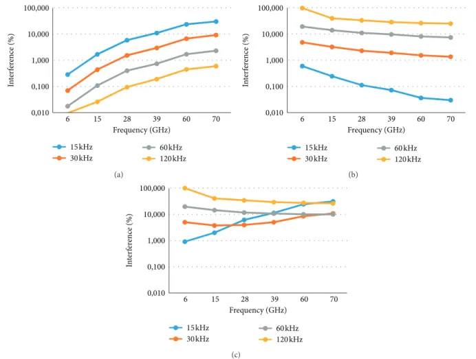
The results corroborated what was previously explained, i.e., when increasing the speed, the ICI caused by the Doppler spread also increases, while changing numerology and increasing the subcarrier spacing, the CP is reduced and the signal becomes more prone to the ISI and ICI caused by insufficient CP. By adding up the interference of both effects, it is possible to obtain the total percentage of interference of the system for each different scenario. In Figure 4, it is possible to observe a comparison between the interference caused by the Doppler spread; the interference caused by insufficient CP; and the total interference of an UMa sce-nario at 120 km/h. In the graph of the interference caused by Doppler spread, it can be seen how for the cases of 15 kHz
and 30 kHz subcarrier spacing, the interference increases as the frequency increases, while for 60 kHz and 120 kHz subcarrier spacing, there is hardly an increase in the in-terference. On the other hand, in the graph of interference caused by insufficient CP, it can be appreciated that for a 120 kHz subcarrier spacing interference, the DS is so large that the echoes completely overlap the next symbol; therefore, this would mean a 100% ISI case. Finally, by considering both interferences, it is possible to determine the best numerology according to the band in use.
Figure 5 shows which numerology can be used according to the operation frequency, speed, and topology. The first thing to note is that for frequencies <3 GHz, the results show that the 15 kHz subcarrier spacing is the best option and still a valid option for frequencies between 3 GHz and 6 GHz.
UMi street-canyon
RMa
Indoor office
UMa
UMi/UMa 021 Figure 3: Model scenario topology examples.
100,000 10,000 1,000 0,100 0,010 6 15 28 39 60 70 Frequency (GHz) In ter fer ence (%) 15 kHz 30 kHz 60 kHz 120 kHz (a) 100,000 10,000 1,000 0,100 0,010 6 15 28 39 60 70 Frequency (GHz) In ter fer ence (%) 15 kHz 30 kHz 60 kHz 120 kHz (b) 100,000 10,000 1,000 0,100 0,010 6 15 28 39 60 70 Frequency (GHz) In ter fer ence (%) 15 kHz 30 kHz 60 kHz 120 kHz (c)
Figure 4: Interference comparison for an UMa scenario at 120 km/h. (a) Doppler interference. (b) Insufficient CP interference. (c) Total interference. 15 30 60 120 Su bc ar rier spacin g (kH z) f (GHz) ALL ALL ALL
Not suitable for UMi/UMa O2I and UMa 3 6 28 70 At 3km/h UMi/UMa O2I UMa RMa Indoor office UMi street‐canyon
This is something to be expected since it is the spectrum used for LTE, which corroborates that 4G systems are currently working optimally. However, for the <3 GHz band, it is possible to use different subcarrier spacing; i.e., 30 kHz subcarrier spacing can be used in UMi Street-canyon, In-door office, RMa, and UMi/Uma O2I environments, while 60 kHz and 120 kHz subcarrier spacings can be used in Indoor office and RMa environments. Regarding the 3–6 GHz band, where the recommendation is to use a 30 kHz subcarrier spacing, Figure 4 shows that as in the <3 GHz band, it is possible to use a 15 kHz subcarrier spacing in UMi Street-canyon, Indoor office, RMa, and UMi/Uma O2I environments and also 60 kHz and 120 kHz subcarrier spacings in Indoor office and RMa environments. An interesting detail is that for this range of frequencies (3–6 GHz), in both Indoor office environment and RMa environment, it is possible to use any numerology since the total interference does not exceed 1%.
For frequencies between 6 and 28 GHz (before mmWave), the recommendation is to use a 60 kHz sub-carrier spacing, but as shown in Figure 5, it is possible to use a 15 kHz subcarrier spacing in the case of Indoor office environments and both 30 kHz and 120 kHz subcarrier spacings for UMi Street-canyon and Indoor office environments.
Regarding the mmWave band, it is recommended to use a 120 kHz subcarrier spacing; however, for UMi/UMa O2I and UMa topologies, the interference levels using this numerology are not in acceptable ranges, which is why in these scenarios, it is better to use a 60 kHz spacing subcarrier. Other topologies that allow the use of a 60 kHz subcarrier spacing in mmWave are Indoor office and UMi Street-canyon. Regarding the 15 kHz and 30 kHz subcarrier spacing numerologies, in mmWave, it can be used in any topology (except for RMa, since the channel model used does not allow to scale the DS for frequencies >6 GHz), as long as it is at low speeds, i.e., pe-destrians moving at an average speed of 3 km/h.
5. Conclusions
Changes in 5G NR numerology have a significant impact on the total system interference, and its influence can be greater or less depending on the system conditions. This has been verified according to the results obtained and the analysis of the ICI and ISI under diverse parameters such as frequency, topology, and UE speed. However, as explained before, increasing subcarrier spacing involves a trade-off between the ICI effect and the ISI effect over the performance of the system. Therefore, by quantifying this interference, it has been possible to determine the best numerology for each of the analysed scenarios within the landscape of 5G.
From the results obtained, it can be concluded that the operating frequency should not be the only parameter to take into account when deciding which numerology should be used in a given system. All 5G OFDM numerologies can be used throughout the 5G spectrum, depending on the characteristics of the system. Thus, contrary to what was recommended, 120 kHz is not necessarily the best option for mmWave, since the trade-off between the ICI effect and the
ISI effect is not better than the obtained with a 60 kHz subcarrier spacing.
Future work includes analysis adding mobility to the base station, so that the UE is not the only element with a travel speed. This could be useful to determine the best 5G OFDM numerology for systems where base stations are drones that constantly change height and position, in order to maximize coverage, reaching even sectors with difficult access.
Data Availability
The datasets generated and analysed during the current study are available in the figshare repository (https://doi.org/ 10.6084/m9.figshare.13067060.v1).
Conflicts of Interest
The authors declare that there are no conflicts of interest regarding the publication of this paper.
References
[1] 3GPP, “Study on New Radio (NR) access technology (release 14),” Technical Report 38.912 v14.0.0, March 2017. [2] A. Osseiran, J. F. Monserrat, and P. Marsch, 5G Mobile and
Wireless Communications Technology, Cambridge University Press, Cambridge, UK, 2016.
[3] 3GPP, “Cellular system support for ultra-low complexity and low throughput Internet of things (Ciot),” Technical Report 45.820 v13.1.0, December 2015.
[4] I. Da Silva, S. E. El Ayoubi, O. M. Boldi et al., 5G RAN Ar-chitecture and Functional Design, METIS II White Paper, 2016.
[5] F. Schaich and T. Wild, “Waveform contenders for 5G: OFDM vs. FBMC vs. UFMC,” in Proceedings of the 6th In-ternational Symposium on Communications, Control and Signal Processing (ISCCSP), pp. 457–460, Athens, Greece, May 2014.
[6] A. Aminjavaheri, A. Farhang, A. RezazadehReyhani et al., “Impact of timing and frequency offsets on Multicarrier Waveform candidates for 5G,” in Proceedings of the IEEE Signal Processing and Signal Processing Education Workshop (SP/SPE), pp. 178–183, Salt Lake City, UT, USA, 2015. [7] R. Gerzaguet, N. Bartzoudis, L. G. Baltar et al., “The 5G
candidate waveform race: a comparison of complexity and performance,” EURASIP Journal on Wireless Communications and Networking, vol. 2017, no. 1, p. 13, 2017.
[8] J. Vihri¨al¨a, A. A. Zaidi, V. Venkatasubramanian et al., “Nu-merology and frame structure for 5G Radio access,” in Pro-ceedings of the IEEE 27th Annual International Symposium on Personal, Indoor, and Mobile Radio Communications (PIMRC), pp. 1–5, Valencia, Spain, September 2016. [9] A. Yazar and H. s. Arslan, “Flexible multi-numerology
sys-tems for 5G New Radio,” Journal of Mobile Multimedia, vol. 14, no. 4, pp. 367–394, 2018.
[10] A. F. Demir and H. Arslan, “Inter-numerology interference management with adaptive guards: a cross-layer approach,” IEEE Access, vol. 8, pp. 30378–30386, 2020.
[11] A. B. Kihero, M. S. J. Solaija, and H. Arslan, “Inter-numer-ology interference for beyond 5G,” IEEE Access, vol. 7, pp. 146512–146523, 2019.
[12] A. Yazar and H. Arslan, “Reliability enhancement in multi-numerology-based 5G New Radio using ini-aware schedul-ing,” EURASIP Journal on Wireless Communications and Networking, vol. 2019, no. 1, p. 110, 2019.
[13] S. Chen and C. Zhu, “ICI and ISI analysis and mitigation for OFDM systems with insufficient cyclic prefix in time-varying channels,” IEEE Transactions on Consumer Electronics, vol. 50, no. 1, pp. 78–83, 2004.
[14] D. Tse and P. Viswanath, Fundamentals of Wireless Com-munication, Cambridge University Press, Cambridge, UK, 2005.
[15] T. Wang, J. G. Proakis, E. Masry et al., “Performance deg-radation of OFDM systems due to Doppler spreading,” IEEE Transactions on Wireless Communications, vol. 5, no. 6, pp. 1422–1432, 2006.
[16] 3GPP, “Technical specification group Radio Access Network; channel model for frequency spectrum above 6 GHz (release 14),” Tech. Rep. 38.900 v14.2.0, December 2016.
[17] 3GPP, “Way forward on further evaluation assumptions for NR waveform,” TDoc. R1-165759, August 2016.
[18] G. W. Paper, 5GCM White Paper for Bands up to 100 GHz, http://www.5gworkshops.com/5GCM.html, 2015.
![Table 2 [16] shows different scaling factors, which have been chosen in such a way that the RMS delay spread covers the entire range observed in the measurements corre-sponding to the proposed 5G scenarios](https://thumb-eu.123doks.com/thumbv2/9libnet/5454357.105066/4.900.106.799.104.304/different-scaling-factors-observed-measurements-sponding-proposed-scenarios.webp)