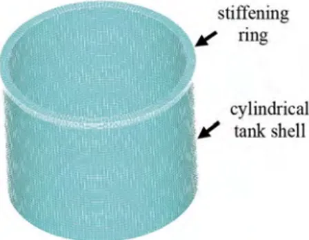
Buckling assessment of cylindrical steel tanks with top stiffening ring under wind loading
Tam metin
Şekil
Benzer Belgeler
Figure 9 shows very different results in convective period, with the open tank and the values in the flat-closed tank overlapping at the same time, the torispherical tank
Two types of material were used: three steel strut of different length with pin and fixed ends, and six aluminium pin-end struts of different lengths.. Each strut was
In order to demonstrate the differences in evaluating the effective length factor (K-Factor) and critical elastic buckling load of an unbraced steel column with rigid and semi-rigid
In this study the lateral torsional buckling (LTB) failure mode of steel cellular beams
Table C.5: Weights of columns, beams, braces and total by having different steel brace profiles for cross bracing in the core of the structure for asymmetrical plan and
In Fig. 19., W eff and e E values calculated for NT4-A, NT5-C, and NT6 samples are given together in the bar graph. At this stage, the NT3-A sample, which had a low performance in
Kanım Türk kaniyle yoğrulmuş, vücudum Türk kaniyle beslenmiş, dimağım Türk hukukunun müdafaa- siyle harbetmiş bir adamımdır.. Hayatımın nihayetine, ölüme
Kuşkonmaz-Çıldır(2008) tarafından gerçekleştirilen ve Ankara ili ilkokul kademesinde görev yapan okul yöneticileri ve öğretmenler arasında takas kuramının
