INVESTIGATION AND SIMULATION OF RESISTANCE SPOT WELDING USING DP600 STEEL IN AUTOMOTIVE INDUSTRY
A THESISeSUBMITTED.TO
THE INSTITUTE OF GRADUTE PROGRAMS OF KARABUK UNIVERSITY
KARABUK UNIVERSITY
BY
ABDULKARIM R. OMER ALZAHOUGI
IN PARTIAL FULFILLMENT OF THE REQUIREMENTS FOR THE DEGREE.OF DOCTOR OF. PHILOSOPHY IN
DEPARTMENT.OF
MANUFACTURING ENGINEERING.
“I declare that all the information within this thesis has been gathered and presented in accordance with academic regulations and ethical principles and I have according to the requirements of these regulations and principles cited all those which do not originate in this work as well.”
ABSTRACT
Ph.D. Thesis
INVESTIGATION AND SIMULATION OF RESISTANCE SPOT WELDING USING DP600 STEEL IN AUTOMOTIVE INDUSTRY
ABDULKARIM R. OMER ALZAHOUGI
KarabükeUniversity Institute of Graduate Programs Department of Manufacturing Engineering
Thesis Advisor: Prof. Dr. Bilge DEMĠR January 2020, 156 pages
The aim of this study is to investigate the weldability and quality of spot resistance welded joints of advanced strength steels in DP 600 sheet steel by theoretical and experimental methods. Today, spot resistance welding is a predominantly manufacturing process in automotive body manufacturing, which necessary strict monitoring of welding quality. Destructive and non-destructive material inspection techniques are used extensively in the determination and development of welding quality and world standards on welding quality are being developed and applied to provides the best weldability. According to the general acceptance the most important result for welding quality and validity is the nugget geometry. Since many different welding parameters can be used in spot resistance welding processes, it is very useful to create a welding map of welded joint materials and the most suitable welding parameters according to their thickness and the welding properties it can provide.
In this study, commercial DP600 automotive sheet steel pairs were examined experimentally; Different welding time, different welding current and different welding electrode pressure parameters are combined with resistance spot welding. Tensile shear test was applied to determine the effect of welding parameters on the tensile load carrying capacity of resistance spot welded joints. In addition, according to optical microscopic images and the Scanning Electron microscope (SEM), were investigations used as the material characterization technique. the phase of base metal contains of a certain amount of hard martensite phase in a soft ferrite matrix, which is changed to a certain amount of ferrite in martensite phase in HAZ while in FZ the phase is almost of lath martensite lath Martensite is thought to form and contains very thin Lath or retained austenite between laths.
Theoretically, SIMUFACT, TAQUCHI and ANOVA programs and software were used for analysis and optimization. Experimental and theoretical study results showed that welding mechanical properties improved with increasing welding time and welding current but decreased with increasing electrode pressure. Both studies showed that welding current and electrode pressure was very effective. The optimum value of tensile shear and Nugget diameter development was determined and compared with the experimental studies it was at welding current 8 kA and clamping load 3.5 bar. To identify the type of failure mode, macroscopic inspection was made on the spot-welding samples, which passed the tensile shear strength. The PF is generally always preferred to the failure mode. The failure mode in this thesis occurs at HAZ and BM.
The results showed in Minitab software Taquchi (DOE) and analysis of Anova the effect of welding current is more effect of clamping load. At the welding current increase the tensile shear load bearing capacity of RSW samples and Nugget formation increase at constant the time whereas increase the clamping load lead to decrease the tensile shear load bearing capacity and nugget formation.
Keywords : Resistance Spot Welding, Dual-Phase Steel, Mechanical Properties, Microstructure, Finite Element Method, Optimization.
ÖZET
Doktora Tezi
OTOMOTĠV DP600 ÇELĠĞĠ KULLANILARAK NOKTA DĠRENÇ KAYNAĞININ SĠMÜLASYONU VE ĠNCELENMESĠ
ABDULKARIM RAMADAN OMER ALZAHOUGI
Karabük Üniversitesi Lisansüstü Eğitim Enstitüsü Ġmalat Mühendisliği Anabilim Dalı
Tez Danışmanı: Prof. Dr. Bilge DEMĠR
Ocak 2020, 156 sayfa
Bu çalışmanın amacı, DP 600 sac çeliği özelinde ileri dayanımlı çeliklerin Nokta direnç kaynaklı birleştirmelerinin kaynak kabiliyeti ve kalitesinin teorik ve deney yolu ile incelenmesidir. Günümüzde otomotiv gövde imalatında Nokta direnç kaynağı ağırlıklı bir imalat olması kaynak kalitesinin sıkı olarak takibe dilmesi ihtiyacını doğurmaktadır. Kaynak kalitesinin belirlenmesi ve geliştirilmesinde tahribatlı ve tahribatsız malzeme muayene teknikleri yoğun olarak kullanılmakta ve kaynak kalitesi üzerine dünya standartları her geçen gün daha geliştirilerek uygulanmaktadır. Genel kabule göre Kaynak kalitesi ve geçerliliği için en önemli sonuç ve gösterge esasında NDK düğme geometrisidir. Nokta direnç kaynak işlemlerinde çok farklı kaynak parametreleri kullanılabildiği için kaynaklı birleştirme malzemeleri ve kalınlığına göre en uygun kaynak parametre ve sağlayabildiği kaynak özelliklerinin kaynak haritasının oluşturulması oldukça faydalıdır.
Bu çalışmada deneysel olarak inceleme için ticari DP600 otomotiv sac çelik çiftleri; farklı kaynak zamanı, farklı kaynak akımı ve farklı kaynak elektrot basıncı parametrelerinin kombinasyonu kullanılarak nokta direnç kaynağı ile birleştirilmiştir. Nokta direnç kaynaklı birleştirmelerin çekme yük taşıma kapasitesine kaynak parametrelerinin etkisini belirlemek amacıyla çekme makaslama testi uygulanmıştır. Ayrıca malzeme karakterizasyon tekniği olarak detaylı optik ve stereo metalografi, SEM-EDS incelemeleri kullanılmıştır. Teorik olarak analiz ve optimizasyon için SIMUFACT, TAQUCHI ve ANOVA program ve yazılımları kullanılmıştır. Deney ve teorik çalışma sonuçları kaynak zamanı ve kaynak akımının artması ile kaynak mekanik özelliklerinin geliştiğini fakat elektrot basıncının artması ile azaldığını göstermiştir. Her iki çalışmada da kaynak elektrot basıncının çok etkili olduğu görülmektedir. Teorik çalışmalar ile optimum düğme çapı gelişimi belirlenmiş ve deney çalışmaları ile kıyaslanmıştır ve optimum kaynak parametresi olarak 8 kA ve 3.5 bar elektrot basıncı belirlenmiştir. Kırılmış numunelerin makro ve mikro incelenmesinde yırtılma ile kırılmaların ana malzemeden, fakat pull out-düğme çıkması kırılmalar söz konusu olduğunda kırılmanın ITAB ve kaynak metalinden olabildiği gözlemlenmiştir. Minitab software Taquchi (DOE) and analysis of Anova analiz sonuçları kaynak akımının kaynak baskı kuvvetinden çok daha etkili olduğunu göstermektedir. Kaynak akımının artması ile NDK kaynak düğme çapı ve NDK kaynaklı birleştirme çekme makaslama maksimum taşıma kuvveti artarken, NDK kaynak baskı kuvvetinin artması ile çekme makaslama maksimum taşıma kuvveti ve düğme çapı azalmaktadır.
Anahtar Kelimeler : Nokta Direnç kaynağı, çift fazlı çelik, mekanik özellikler, mikroyapı, Sonlu elemanlar analizi, optimizasyon.
ACKNOWLEDGMENT
The name of Almighty Allah, the praise is to the God. The work was carried out in the Faculty of Technology at Karabük University, between September 2016 and December 2019 under the supervision of Prof. Dr. Bilge DEMIR, whom I would like to thank sincerely for his encouragement, guidanceeand advice throughout experimental work and for his constructive criticism during the preparation of this thesis.
I am also particularly grateful to Dr. Muhammed Elitas and Mustafa Göktaş for carrying out some experiment, and for their advice and support. I would like to thank also all staff in the department foretheir help.
I am thankful toemy Mother, my Sister and my wife, for their patience and commendable support during the preparation of this thesis. I cannot forget my children, whose have been a great motivating force during these tense moments. I would like to extent my thanks also to my brothers and for their kind support. I would like also to extent my thanks to my friendship of Ali Kheiry for his help.
CONTENTS Page APPROVAL ... ii ABSTRACT ... iv ÖZET... vi ACKNOWLEDGMENT ... viii CONTENTS ... ix
LIST OF FIGURES ... xiv
LIST OF TABLES ... xix
LIST OF SYMBOLS AND ABBREVITIONS INDEX ... xx
PART 1 ... 1
INTRODUCTION ... 1
1.1. PREFACE ... 3
1.2. BACKGROUND ... 4
1.3. THE OBJECTIVE OF THE THESIS ... 6
PART 2 ... 7
ADVANCED HIGH STRENGTH STEEL (AHSS) ... 7
2.1. WELDING OF ADVANCED HIGH STRENGTH STEELS ... 8
2.2. CLASSIFICATION OF ADVANCED HIGH STRENGH STEEL (AHSS) ... 8
2.3. DUAL PHASE STEELS (DP) ... 10
2.3.1. Classification of DP Steels ... 11
2.3.2. Microstructure of DP Steel ... 12
2.3.3. Mechanical Properties ... 14
2.3.3.1. Tensile Properties... 16
2.3.3.2. Relationship between Ultimate Tensile Strength and Uniform Elongation of Many Steels ... 16
2.3.3.3. Relationship between Yield Strength and Ultimate Tensile Strength for Various Types of Steels (Yield Ratio) ... 17
Page 2.3.3.4. Evaluation of Macrostructure and Weld Nugget Geometry of
Weldment ... 18
2.3.4. Processing of Dual Phase Steel (DP) ... 19
2.3.5. Dual Phase Steel in Automotive Industry ... 22
PART 3 ... 24
RESISTANCE WELDING AND SPOT WELDING AND THEIR COMBINATION ... 24
3.1 CLASSIFICATION OF RW AND SW AND THEIR COMBINATION ... 25
3.2. RESISTANCE WELDING ... 25
3.2.1. Resistance welding processes ... 25
3.2.1.1. Spot Welding ... 26
3.2.1.2. Resistance Seam Welding ... 27
3.2.1.3. Resistance Projection Welding ... 28
3.2.1.4. Resistance Butt Welding ... 29
3.3. SPOT WELDING (LASER WELDING, STIR WELDING) ... 30
3.3.1. Laser Welding ... 30
3.3.2. Friction Stir Welding ... 31
3.4. RESISTANCE SPOT WELDING ... 32
3.4.1. Principle Working and Thermo Electrical Process of RSW ... 34
3.4.2. Resistance Spot Welding of DP Steel ... 36
3.4.3. Resistance Spot Welding Processing ... 38
3.4.4. Resistance Spot Welding Parameters ... 40
3.4.4.1. Welding Current... 41
3.4.4.2. Welding Time ... 42
3.4.4.3. Welding Force ... 43
3.4.4.4. Geometry and Dimensions ... 45
3.4.4.5. Electrode Degradation and Tip Dressing ... 45
3.4.4.6. Mechanisms of Electrode Degradation ... 45
3.4.4.7. Effects of Electrode Degradation ... 46
3.4.4.8. Diameter of the Electrode Contact Surface ... 47
3.4.5. Electrode Materials ... 48
Page
3.5.1. Penetration and Indentation in RSW of DP Steel ... 51
3.6. MICROSTRUCTURE... 53
3.7. MECHANICAL PROPERTIES OF RSW JUNCTION ... 58
3.7.1. Tensile Load Bearing Capacity ... 58
3.7.2. Tensile Shear Failure Behavior ... 59
3.7.3. Stroke Displacement ... 61
3.7.4. Hardness Profile... 62
PART 4 ... 63
EXPERIMENTAL AND THEORETICAL STUDIES ... 63
4.1. MATERIALS ... 63
4.2. WELDABILITY OF MATERIALS USED IN EXPERIMENTAL STUDY 64 4.3. SAMPLES PART OF RESISTANCE SPOT WELDING ... 66
4.4. RESISTANCE SPOT WELDING PROCESS ... 67
4.4.1. Resistance Spot Welding Machine ... 68
4.4.2. Resistance Spot Welding Parameters ... 70
4.5. MECHANICAL TESTING ... 72
4.5.1. Tensile Shear Test... 72
4.5.2. Hardness Measurement ... 74
4.6. METALLOGRAPHIC AND MICROSTRUCTURAL EXAMINATIONS . 76 4.7. RESIDUAL STRESS ... 76
PART 5 ... 78
MODELING AND SIMULATION, OPTIMIZATION AND ITS TECHNIQUE OF RESISTANCE SPOT WELDING ... 78
5.1. MODELING OF RSW ... 78
5.1.1. Governing Equation ... 79
5.2. CLASSIFICATION OF MODELING ... 79
5.2.1. Comsol Multiphysics Software... 79
5.2.2. Simufact Software ... 79
Page
5.4. CLASSIFICATION OF OPTIMIZATION (MINITAB) ... 81
5.4.1. (Experimental of Desgine) Taquchi... 81
5.4.2. ANOVA ... 81
PART 6 ... 82
RESULTS AND DISCUSSION ... 82
6.1. MICROSTRUCTURE... 82
6.2. THE EFFECT OF WELDING CURRENT ON THE MICROSTRUCTURE ... 83
6.2.1. The Effect of Welding Current on Microstructure ... 83
6.2.2. Effect of Electrode Force on the Microstructure of -Dp600 Steel Weldment ... 90
6.3. NUGGET FORMATION ... 98
6.4. SIMU FACT SIMULATION ... 100
6.5. TENSILE SHEAR TEST ... 105
6.5.1. Maximum Tensile Shear Strength Values ... 105
6.5.2. Tensile Shear Load Bearing Capacity vs current with clamping load.. 106
6.5.3. Tensile Shear Load Bearing Capacity vs clamping load with current.. 108
6.5.4. Effects of the Clamping Load on Nugget Formation ... 111
6.6. EFFECTS OF WELDING CURRENT ON NUGGET FORMATION ... 114
6.7. THE FAILURE MODE ANALYSIS OF TENSILE TESTED DP600 ... 118
6.8. HARDNESS MEASUREMENT ... 120
6.9. RESIDUAL STRESS ... 123
6.10. MINITAB TAQUCHI ... 125
6.10.1. Taguchi Design ... 125
6.10.2. Tensile Shear Strength ... 126
6.10.2.1. The Effect of Parameters on Signal to Noise Ratio ... 126
6.10.2.2. The Analysis of Parameters for Means ... 128
6.10.3. Nugget Diameter ... 129
6.10.3.1. The Analysis of Parameters on Signal to Noise Ratio ... 129
6.10.3.2. The Analysis of Parameters for Means ... 131
6.10.4. Analysis Variance (ANOVA) ... 132
Page
PART 7 ... 135
CONCLUSION ... 135
REFERENCES ... 141
LIST OF FIGURES
Page
Figure 1.1. Ford Model T from 1908 ... 4
Figure 1.2. Mercedes-Benz concept style coupe (preview 2013 CLA-Class) at 2012 Paris Auto Show. ... 4
Figure 2.1. The microstructure of DP steel. ... 13
Figure 2.2. Tensile curves of HSLA, DP350/600,and TRIP350/600 steels... 15
Figure 2.3. Summary of relationship of tensile strength (UTS) and tensile elongation (Uniform) for numerous members of tradational and advanced high -multi strength sheet steels (AHSS) . ... 17
Figure 2.4. Relationship between yield strength and total elongation for many types of steels... 18
Figure 2.5. Weld nugget diameter sections of weldment . ... 19
Figure 2.6. Illustration of the lever rule . ... 21
Figure 2.7. Intercritical annealing of DP steel . ... 21
Figure 2.8. Applications of DP steels in automotive industry . ... 23
Figure 3.1. Classification of Resistance welding . ... 25
Figure 3.2. Resistance Spot Welding . ... 27
Figure 3.3. Seam welding machine . ... 28
Figure 3.4. Seam welding . ... 28
Figure 3.5. Projection welding . ... 29
Figure 3.6. Butt Welding ... 30
Figure 3.7. Laser welding . ... 31
Figure 3. 8. Friction stir welding ... 32
Figure 3. 9. Basic single pulse welding cycle for resistance spot welding . ... 33
Figure 3.10. The schematic illustration of resistance spot welding processes . ... 34
Figure 3.11. The schematic illustration of electrical RSW . ... 35
Figure 3.12. Resistance spot welding processing weld time parameters . ... 39
Figure 3.13. Welding Current Parameters ... 41
Figure 3.14. Weld Time Parameters . ... 43
Page
Figure 3.16. Electrodes Tip . ... 46
Figure 3.17. Example of a severely pitted electrode. . ... 47
Figure 3.18. Electrode geometry types ... 48
Figure 3.19. Effect of the clamping load on the nugget formation . ... 50
Figure 3.20. Effect of the input current on the nugget formation . ... 50
Figure 3.21. Penetration in the RSW. ... 51
Figure 3.22. Indentation in The Rsw ... 52
Figure 3.23. Typical macrostructure of resistance spot welds showing the weld physical attributes including FZ size D, electrode indentation depth ti and the width of HAZ XHAZ. The presence of a natural notch at the sheet/sheet interface significantly affects the m behaviour of resistance spot welds . ... 54
Figure 3.24. Micrograph of Ristenace Spot Welding joint of 3 sheets. The grains direction in the weld nugget extends along with cooling lines vertically. The cooling is directed to the cooled electrode by water horizontally along with the medium line wher the cooling is directed to to the su rounding material. ... 55
Figure 3.25. The distinctive microstructure of a resistance spot-welded DP600 steel joint where the micrographs locations a to d are indicated: a) DP600 OHAZ; b) DP600 CHAZ; c) DP600 IHAZ; d) FZ. PF: polygonal ferrite; M: martensite; TM: tempered mart ensite; B: bainite; M/A: martensite–austenite. ... 57
Figure 3.26. Simple models describe the stress distribution at the interface and circumference of a weld nugget through a) TS,[96] b) CT and c) CP tests ... 59
Figure 3.27. Diagram explanation of three distinctive failure modes . ... 60
Figure 3.28. Distinctive load–displacement curve thorugh the tensile strength test with the extracted parameters: Wmax: energy absorption; Lmax: elongation at peak load Pmax: peak load; . ... 61
Figure 3.29. Diagram of desntinctive hardness profile of resistance spot welds made ... 62
Figure 4.1. Microstructure view of DP600 steel. ... 64
Figure 4.2. The weldability of the steels assessed by Graville diagram ... 66
Figure 4.3. Geometry of the Sample. ... 67
Figure 4.4. RSW sample image. ... 67
Figure 4.5. Spot welding machine in this study ... 69
Page Figure 4.9. Tensile Test Dimensions. ... 73 Figure 4.10. Tensile test machine used for testing. ... 74 Figure 4.11. The hardness measurement on the diagonal of the weld cross section.. 75 Figure 4.12. The macrograph of Vickers microhardness test machine. ... 75 Figure 4.13. Residual stress measurement equipment of specimens. ... 77 Figure 6.1. Microstructure of DP600 ... 82 Figure 6.2. The weld zone profile and its microstructures of DP600 weldment
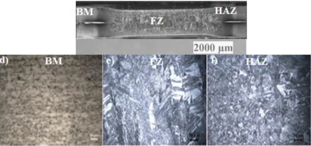
joined with 3.5 Bar electrode force with 4kA welding current. a) base metal (BM), b) Heat Affect Zone (HAZ), c) weld nugget (FZ). 83 Figure 6.3. The microstructure of weldment joined with 3.5 Bar electrode force
with 6kA welding current. a) DP600 base metal (BM), b) DP600 Heat
Affect Zone (HAZ), c) DP600 weld nugget (FZ). parameters of (3.5 Bar – 6 kA) ... 85 Figure 6.4. The microstructure of weldment joined with 3.5 Bar electrode force
with 8kA welding current. a) DP600 base metal (BM), b) DP600 Heat
Affect Zone (HAZ), c) DP600 weld nugget (FZ). parameters of (3.5 Bar – 8 kA) ... 85 Figure 6.5. The weld zone profile and its microstructures of DP600weldment
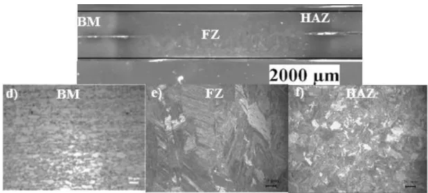
joined with 4.5 Bar electrode force with 4kA welding current.
d) DP600 base metal (BM), e) DP600 Heat Affect Zone (HAZ), f) DP600 weld nugget (FZ) ... 87
Figure 6.6. The microstructure of weldment joined with 4.5 Bar electrode force with 6kA welding current. d) DP600 base metal (BM), e) DP600 Heat Affect Zone (HAZ), f) DP600 weld nugget (FZ). parameters of (4.5 Bar – 6 kA) ... 87 Figure 6.7. The microstructure of weldment joined with 4.5 Bar electrode force with
8kA welding current. d) DP600 base metal (BM), e) DP600 Heat Affect Zone (HAZ), f) DP600 weld nugget (FZ). parameters of (4.5 Bar – 8 kA) ... 88 Figure 6.8. The weld zone profile and its microstructures of DP600weldment joined
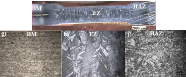
with 5.5 Bar electrode force with 4kA welding current. g) DP600 base metal (BM), h) DP600 Heat Affect Zone (HAZ), j) DP600 weld nugget (FZ) ... 89 Figure 6.9. The weld zone profile and its microstructures of DP600 weldment
joined with 5.5 Bar electrode force with 6kA welding current. g) DP600 base metal (BM), h) DP600 Heat Affect Zone (HAZ), j) DP600 weld nugget (FZ) ... 89 Figure 6.10. The microstructure of weldment joined with 5.5 Bar electrode force with 8kA welding current. g) DP600 base metal (BM), h) DP600 Heat Affect Zone (HAZ), j) DP600 weld nugget (FZ). parameters of (5.5 Bar – 8 kA) ... 90
Page Figure 6.11. The weld zone profile and its microstructures of DP600 weldment
joined with 3.5 Bar electrode force with 4kA welding current. a) base
metal (BM), b) Heat Affect Zone (HAZ), c) weld nugget (FZ) ... 91
Figure 6.12. The weld zone profile and its microstructures of DP600weldment joined with 4.5 Bar electrode force with 4kA welding current. d) DP600 base metal (BM), e) DP600 Heat Affect Zone (HAZ), f) DP600 weld nugget (FZ) ... 92
Figure 6.13. The weld zone profile and its microstructures of DP600weldment joined with 5.5 Bar electrode force with 4kA welding current. g) DP600 base metal (BM), h) DP600 Heat Affect Zone (HAZ), j) DP600 weld nugget (FZ) ... 92
Figure 6.14. The microstructure of weldment joined with 3.5 Bar electrode force with 6kA welding current. a) DP600 base metal (BM), b) DP600 Heat Affect Zone (HAZ), c) DP600 weld nugget (FZ). parameters of (3.5 Bar – 6 kA) ... 94
Figure 6.15. The microstructure of weldment joined with 4.5 Bar electrode force with 6kA welding current. d) DP600 base metal (BM), e) DP600 Heat Affect Zone (HAZ), f) DP600 weld nugget (FZ). parameters of (4.5 Bar – 6 kA) ... 94
Figure 6.16. The weld zone profile and its microstructures of DP600weldment joined with 5.5 Bar electrode force with 6kA welding current. g) DP600 base metal (BM), h) DP600 Heat Affect Zone (HAZ), j) DP600 weld nugget (FZ) ... 95
Figure 6.17. The microstructure of weldment joined with 3.5 Bar electrode force with 8kA welding current. a) DP600 base metal (BM), b) DP600 Heat Affect Zone (HAZ), c) DP600 weld nugget (FZ). parameters of (3.5 Bar – 8 kA) ... 96
Figure 6.18. The microstructure of weldment joined with 4.5 Bar electrode force with 8kA welding current. d) DP600 base metal (BM), e) DP600 Heat Affect Zone (HAZ), f) DP600 weld nugget (FZ). parameters of (4.5 Bar – 8 kA) ... 97
Figure 6.19. The microstructure of weldment joined with 5.5 Bar electrode force with 8kA welding current. g) DP600 base metal (BM), h) DP600 Heat Affect Zone (HAZ), j) DP600 weld nugget (FZ). parameters of (5.5 Bar – 8 kA) ... 97
Figure 6.20. Macro photography of weld nuggets of RSW samples. ... 99
Figure 6.21. Modeling of sample and the Majer Phase... 100
Figure 6.22. The Volume fraction of Martensite transformation. ... 101
Figure 6.23. Volume fraction of ferrite at FZ. ... 102
Page
Figure 6.27. Maximum tensile shear force values obtained at 25 Cycles. ... 106
Figure 6.28. Effect of Current on tensile shear strength at different parameters at 25 Cycles. ... 107
Figure 6.29. Effect of Current on tensile shear strength at different parameters at 15 Cycles weld time. ... 108
Figure 6.30. Effect of Force on tensile shear strength at different parameters at 25 Cycles. ... 109
Figure 6.31. Effect of Force on Tensile shear force values obtained at 15 Cycles weld time. ... 110
Figure 6.32. Effects of the clamping load on nugget formation at time 25 Cycles. 111 Figure 6.33. Effects of the clamping load on nugget formation at time 15 Cycles. 112 Figure 6.34. Comparison between the of the original results with Simulation and researcher results on clamping load on nugget formation. ... 113
Figure 6.35. Effect of the Current on Nugget Formation at 25 Cycles weld time. .. 115
Figure 6.36. Effect of the Current on Nugget Formation at 15 Cycles weld time. .. 115
Figure 6.37. Changing of the nugget diameter with weld current. At this Fig, simufact simulation, a literature. ... 118
Figure 6.38. The microstructure of DP600 a) BM, b) HAZ and c) FZ. ... 119
Figure 6.39. Failure mode in resistance spot welding for BM. ... 119
Figure 6.40. Failure mode Pull out in resistance spot welding for HAZ. ... 120
Figure 6.41. Failure mode Pull out in resistance spot welding for HAZ. ... 120
Figure 6.42. Microhardness Profile with Force 3.5 Bar at different current. ... 122
Figure 6.43. Microhardness Profile with Force 4.5 Bar at different current. ... 122
Figure 6.44. Microhardness Profile with Force 5.5 Bar at different current. ... 123
Figure 6.45. Residual stress values of samples at time of 25 Cycles. ... 124
Figure 6.46. Residual stress values of samples at time of 15 Cycle. ... 125
Figure 6.47. The main Response effects plot of parameters for signal to noise. ... 127
Figure 6.48. Interaction the effect of force and current on signal to noise. ... 128
Figure 6.49. The main Response effects plot of parameters for means. ... 129
Figure 6.50. Response effect of parameters for signal to noise ... 130
Figure 6.51. Interaction the effect of force and current on signal to noise ... 131
Figure 6.52. The main Response effects plot of parameters for means. ... 132
Figure 6.53. The analysis of ANOVA for tensile shear. ... 133
LIST OF TABLES
Page
Table 2.1. Advanced High Strength Steels... 10
Table 2.2. Summarizes the product property requirements for various types of DP steels, according to ArcelorMittal standard 20×80 mm ISO tensile specimens ... 12
Table 2.3. Mechanical properties of DP 600 Steel at different temperature ... 12
Table 2.4. Tensile Properties of the DP steels ... 16
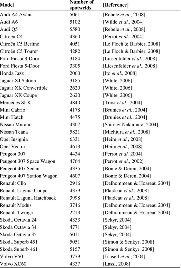
Table 3.1. Number of spot welds used to assemble the Body in White (B.I.W.) of several brands and models, as presented at conferences. If data is available for updated models (e.g. Ford Fiesta), the data of the latest model are presented here ... 37
Table 3.2. The minimum Nugget Diameter at different sheet thickness ... 52
Table 4.1. Chemical composition of DP600 Steel (wt.%) ... 63
Table 4.2. Spot welding machine properties ... 69
Table 4.3. Welding parameters using in this study ... 71
Table 6.1. Changing of weld nugget with welding current and Electrode force clamping load at 25 Cycles ... 99
Table 6.2. Changing of weld nugget with welding current and Electrode force/ clamping load at 15 Cycles ... 99
Table 6.3. The Response Analysis for Signal to Noise Ratios ... 127
Table 6.4. The results of interaction the effect of the parameters for signal to noise ... 128
Table 6.5. The Response Analysis for means. ... 129
Table 6.6. The Response Analysis for Signal to Noise Ratios. ... 130
Table 6.7. The results of interaction the effect of the parameters for signal to noise ... 131
Table 6.8. The Response Analysis for means. ... 132
Table 6.9. Analysis Variance (ANOVA) For Tensile Shear. ... 133
LIST OF SYMBOLS AND ABBREVITIONS INDEX
SYMBOLS
dn : weld nugget diameter
hn : weld nugget height
ei, : electrode indentation
hn/dn : weld nugget size ratio
ABBREVIATIONS
AHSS : Advanced High Strength Steel HSS : High. Strength Steel
TRIP : Transformation Induced Plasticity DP : Dual Phase Steel
TWIP : Twin Induced Plasticity
Ac1 : Temperature of austenite formation on heating
Ac3 : Temperature at which transformation of ferrite into austenite is
completed on heating RSW : Resistance Spot Welding TS : Tensile Strength
UTS : Ultimate Tensile Strength YS : Yield Strength
MPa : Mega Pascal, the unit for tensile strength TSS : Tensile Shear Strength
CTS : Cross Tensile Strength
SEM : Scanning Electron Microscope
EDS : Energy Dispersive X-Ray Spectroscopy HV : Vickers Hardness
FZ : Fusion Zone PF : Pullout Failure
PIF : Partial Interfacial Failure IF : Interfacial Failure
CP : Complex Phase
MS : Martensitic Steel FB : Ferritic Bainitic
PART 1
INTRODUCTION
The increase in the level of production competition obviously has higher and more advanced quality; advanced, lighter, safer, more environmentally friendly, and ultimately more affordable, cheaper materials for the development of modern cars that improve the environment, protection and vehicle performance, thereby inspire all possible standard improvements to new steel grades. Because like traditional low, carbon steel; ultra-deep drawing (EDD), deep drawing (DD), baking hardening (BH), gap free (IF) steel and technically high strength steel (HSS), for example; carbon-manganese steel and high-strength low-alloy (HSLA) steel is now more than ever, and because of the better mixture of ductility and strength. It is even being increasingly replaced by advanced high-strength steel (AHSS). It has now been noted and recognized that the increased strength of metallic materials technically leads to reduce the formability [1].
Conventional HSLA steel with high tensile strength seems to have moderate formability but retains its functional applications in the automotive industry [2]. Recently, phase-induced plasticity (TRIP) steel, dual-phase (DP) steel, and their galvanized products have been extensively used to produce and industrialize the automotive parts including bumper reinforcements, lists and bumper beams. Be one. Together, DP steel and TRIP steel offer great possibility for higher combinations of formability and strength [3-5]. Then, these steels were characterized and subjected to their high work hardening rate, high tensile formability, incessant yield behavior, high tensile strength, high elongation, baking hardening ability (DP), and low yield stress. Grouping high yield strength (TRIP), Tensile stress ratio (DP) and high uniform elongation (TRIP), excellent resistance of corrosion (galvanized products) [6]. In addition, in recent years, steels characterized by twin induced plasticity (TWIP) have attracted attention and are built on such steels. In combination with
high strength under cold deformation conditions, many alloying concepts are provided for TWIP steel to achieve excellent plasticity and ductility [7]. It is well known that TWIP materials are highly alloyed, and in all relevant standards, it is important to note that they have a complete austenitic structure at any given room temperature under processing conditions. TRIP steel is a low alloy steel with a predominant ferrite microstructure. As a part of low alloy steel, the soft ferrite phase combination and hard martensite phase in DP steel brings superior ductility and is work hardened with given tensile strength.
In contrast, the microstructure of TRIP steel involves of bainite, ferrite and retained austenite phases. During the strain process, the metastable residual austenite is transformed into martensite, resulting in transformation-induced plasticity that is considered the main reason for improving durability and plasticity.
The most commonly used method and technique of welding is the Resistance Spot Welding (RSW) by which metal adhesion can be generated and produced on the joint surface. The resistance of the workpiece to the current generates heat at the joint. The principle of resistance spot welding operation includes extrusion time, pre-heating time, welding time, cooling time, post-heating time and final holding time.
Functional operation includes the corresponding application of mechanical pressure and current of appropriate size and duration. Not surprisingly; the welding current should pass from the electrode over the workpiece. The welding current continuity is achieved by applying a load and by applying a load. Shaped electrodes offer the essential pressure and current density. Therefore, sufficient heat is generated to increase the limited metal volume to a molten state. Later, this metal is cooled under pressure until it has the sufficient strength in order to hold the parts together. The welding current and electrode force should form nuggets but not very high as to allow molten metal to escape from the welding area. The welding time should be short enough to inhibit the electrode surface from overheating to avoid shortening the life [8].
A comprehensive study through the literature survey showed and proposed that the number of this study was very limited and related to the resistance spot weldability of AHSS. It is significant to recognize that research on TRIP and resistance spot welding of DP steels has greatly targeted.
1.1. PREFACE
Technology through welding is the most popularly, and universally used method of remaking or making a metal structure that is used to link and assemble different kinds of structures connecting them with surfaces through heat and or pressure on materials such as metals, polymers and even composite. During welding, the melting point of the pieces of work to be connected at the interface to give a good welding joint and solidification. In the late 19th century, France and Germany implemented the blueprint for modern cars [9]. In addition, the revolution of Americans in the early 20th century automotive industry has brought a great advantage to our daily life and the towns have become more compact. But with the side effects of lasting innovation in the automotive industry including the fossil fuel consumption, environmental pollution, and climate change new challenges have been emerged [10].
The main aim in the automotive industry is also that cars and other vehicles have saved fuel from the beginning. Saving the energy every time important energy, this reality took place strongly and strongly during the economic crisis. In the 1970s, there was a serious economic crisis in the world, especially in the United States. Therefore, there has been a huge dispute between the company and the researchers, why should we find energy-saving bodies in white materials, especially automobile body steel. This was mainly done through a speech by and researchers, before the story began, but first it was strongly targeted.
In order to accomplish these goals, the use of lighter materials and light construction are of a high requirement and demand. The car has the same average size in 1908 Figure 1.1. a) And the concept of today, such as a four-wheel starter engine. But compared to modern models, design and efficiency are very different Figure 1.1. b)
Low-cost manufacturing in the automotive industry is one of the key objectives of ever-increasing global competition. Low cost production is often linked to the term light manufacturing term although light technologies may increase production costs in many cases due to the need for new processes and equipment. Also increasing progressively to meet higher safety requirements. Therefore, the development of a new, low-cost, innovative manufacturing process is one of the key objectives in the formation of metal metals: new light production principles are of major importance in these new processes. The two main trends to produce light automotive parts are the application of high-level steels or light materials. There is an important point, what accompanying to that, is manufacturing processes of auto body. These parts are made of formed sheet and conjected via welding particularly spot welding which don‘t need to filler metal and extra metals therefore auto body weight does not increase due to spot welding.
Figure 1.1. a) Ford Model T from 1908, b) Mercedes-Benz concept style coupe (preview 2013 CLA-Class) at 2012 Paris Auto Show [11].
1.2. BACKGROUND
Resistant spot welding (RSW) is an effective and binding process that is extensively used to make metal sheet assemblies. The RSW was created by Elihu Thomson in the 1880s, when he revealed the concept to connect metals through resistance spot welding [12]. Currently, RSW that used now depends on the same basic principles. Nowadays, RSW operates mainly in the automotive industry. Nevertheless, RSW is used in many products including the circuit elements, appliances, aerospace industry
binding process that is widely practiced in the automotive industry. RSW has been used extensively in order to joint sheet metal because of its ease of operation, high production efficiency and high speed and low cost. A modern white body usually has thousands of spots. Advanced High-Strength Steels (AHSS) were viewed as a Dual phase steel (DP) is considered a new solution for fuel proficiency, vehicle safety and cost savings in the automotive industry [14].
RSW is recorded to be one of the oldest forms of welding processes. It is one type of resistance welding, an approach of combining two or more sheets of metal through the application of pressure and heat in the welding area. (RSW) is widely used as junction metal sheets of automotive industry, through heat and pressure to use, also sheets, aluminum is subject to spot-welding, but more use of steels in spot-welding and seam welding which is very important to use automotive industry, for good technique, light weight, low environments and less processing time. RSW, seam and Friction Stir welding are different to other welding process is simple to use, suitable for cars, For example, 7000 to 12,000 spots of welding, of greater speed, no extra (filler) material, less weight and environment according to new assembly automatic. So, spot welding is a significant process in an automatic body assembly [15].
There are some parameters to consider in the spot welding. These parameters will effect on the quality of tests. The suitable combination of the spot-welded parameter creates a robust connection and will be highly visible. Welding parameters include: Electrode force, electrode diameter, squeeze time, Weld time, thickness of sheets and Welding current. Size and number of the welding structure of the welding determines the strength of the component in this process. The size of the spot diameter ranges between 3-12.5 mm [16].
In order to study the strength of spot welds in terms of the welding parameter, base metal strength, welding schedule, specimen geometry, testing speed and testing formation of the tensile test approach can also be used to study the spot-welding strength. To create the thesis framework, the RSW process is offered and described in detail at the following chapters. RSW is a type of resistance welding with its discrete self-characterized areas. Resistant spot welding is dissimilar to arc welding
where RSW consists of a metal binding method in which the materials are connected using an electrical resistance spot welding instead the electric arc [17]. The principle behind the connection approach is passing a current through two or more sheets as a pair of electrodes press them together. In addition, the following situations, advantages, disadvantages and welding devices are described in the following chapters.
1.3. THE OBJECTIVE OF THE THESIS
The objectives of this study can be illustrated as follows :
The main goal of this thesis is to study the RSW of AHSS by examining the process, properties of sheet steel material used in the automotive industry. Characterization of spot welded AHSS microstructure.
Usability and weldability of DP 600 steel in weld structures of automotive industry.
Optimize tensile shear strength, Nugget Formation, indentation depth of the electrode force and mechanical properties (microhardness test) for all of WM, HAZ and BM.
Investigate and choosing the right and optimal control of the parameters including welding current, welding time and electrode force to get on the best weldability.
Also compare and optimize the experimental results with simulation results such as Taguchi (Minitab 17 software) and Anova, Also Simufact software.
PART 2
ADVANCED HIGH STRENGTH STEEL (AHSS)
Advanced high strength steels (AHSS) are engineering materials that combine higher strength (performance), good ductility (formability) and excellent energy absorption (crashworthiness). Global demand for energy saving and increasing concern for environmental pollution and global warming affect the scientific community and relevant studies are on the rise. The improvement of strength, capacity and properties of materials, most importantly metals, reduces material cross section, the reduction of part weight and the resultant decrease in fuel consumption, has made possible to reduce greenhouse gas emissions. For various functional requirements of current vehicles, advanced high strength steel is the ideal solution [18].
In the 1980s, automotive faced many challenges to enhance safety, reducing fuel and weight consumption. Advanced High Strength Steel (AHSS) levels contribute significantly to safety, exhaust gas pollution, good formability, viability, fuel efficacy, durability, environmental policy and quality requirements at relatively low cost [19]. Consistent with steel makers, AHSS is a new generation of steel that offers very high strength and other beneficial mechanical features whereas preserving high capacity. Advanced High Strength steels (AHSSs) combine between ductility and strength by phase transformation and solution reinforcement and accomplish a strength-to-weight rate of light applications in the automotive industry [20,21]. The content of carbon and use classify the steels [22]. Carbon steels (0 – 0,30 wt% C) are the most significant for the integrity of structure for the automotive vehicle as they structure the Body in White (BIW). The plain carbon steels features depend mainly on their microstructure and carbon content.
The main beneficial effect of these alloying elements is increasing toughness and strength in addition to the material hardenability. Practically, the stiffness is not effected [9]. The plain carbon steels by quality of their microstructural homogeneousness and low carbon content, generally present good formability and weldability and both of them provide great significance in automotive industry. Nevertheless, increasing strength is required in automotive industry for the purpose of performance. It is possible to increase the strength by the cold working. However, this is limited because of the chemical composition of the steel. Increasing level of alloying will increase the cost and have positive impact on weldability. High Strength Low Alloyed (HSLA) steels have been developed to enhance toughness and strength of steels at the same time retaining good weldability [23]. In general, low alloyed steels contain silicon and manganese and may show both good formability and high strength, if they are first heat preserved to create a matrix of ferrite with islands of martensite [24]. The Advanced High strength steels (AHSS) combine between ductility and strength through phase transformation and solution strengthening and accomplish a strength-to-weight rate for light applications in the automotive industry [20,21].
2.1. WELDING OF ADVANCED HIGH STRENGTH STEELS
The industry witnessed the emergence of many joining techniques and methods for advanced high strength steel. Since TRIP and DP steels have been selected for the automobiles industry, spot welding is considered one of the most significant joining methods of these types of steels [3,25]. The study of RSW for TRIP and DP steels is directed to steels with tensile strengths under 980 MPa, equal mixture and simple welding processes [26-28]. Thus, at the next section, we will provide information about RSW.
2.2. CLASSIFICATION OF ADVANCED HIGH STRENGH STEEL (AHSS)
Advanced high strength steel (AHSS), reached much higher tensile strength than the conventional high strength steel (HSS). One of the most important and valuable
several types of advanced high strength steels (AHSS) which can be categorized according to the processing, and mechanical features of the material. Nowadays, the most frequently used types include High strength low alloy (HSLA), dual-phase (DP), complex phase (CP), martensitic steel (MS), transformation induced plasticity (TRIP), ferritic bainitic (FB) and martensite (MART) twinning-induced plasticity (TWIP) [29], Among the characteristics associated with the equipped 590R, there are enhanced formability together with high strength has met ample range of applications in the automobile industry. this new steel has been developed based on a stable weldable alloy with low levels of carbon and alloying elements [30].
High Definition Path and Types of AHSSs are families of steels that are stronger and have higher formability or ductility than conventional high strength steels (HSSs), reported by Bouaziz et al. 2013, keeler et al. 2014 and Kuziak et al. 2008 [31,32]. It is possible to distinguish between the AHSS family and the strength levels that can be roughly defined: product yield strength> 300 Mpa and ultimate tensile> 600 Mpa. The fuel economy is a key factor and therefore a weight reduction for the automotive industry [33-37]. Light vehicles were developed with high passive quality using high level steels, such as multiphase steels. These include an excellent choice of dual-phase steels (DP) which its microstructure is composed mostly of ferrite and martensite, for applications with low yield strength, high tensile strength, continuous result and uniform elongation required the main materials of AHSS are TRIP and DP steels.
Other types of AHSS were developed and all of them have a microstructure involving two or more different phases, of which (at least) one adds hardness and strength to the materials while the others deliver more formability as shown in Table 2.1.
Table 2.1. Advanced High Strength Steels [38].
AHSS Microstructure Composition
DP Dual Phase steel ferrite, martensite [LLewellyn & Hudd 2000]
TRIP Transformation Induced Plasticity steel
ferrite, bainite, retained austenite [LLewellyn & Hudd 2000] CP Complex Phase steel martensite, pearlite, retained austenite
[IISI, 2006]
FB Ferritic Bainitic steel ferrite, bainite [IISI, 2006] MS Martensitic Steel martensite, bainite, ferrite [IISI, 2006] Q&P Quenching & Partitioning steel martensite, ferrite, retained austenite.
[Wang & Weijun, 2011
Since Hot Forming (HF) steels and Twinning-Induced Plasticity (TWIP) steels are sometimes showed enhanced formability and strength, they grouped under heading AHSS [38] Nevertheless, they do not include complex microstructural composition which sets AHSS apart from HSLA steels. In addition, while the chemical composition of TWIP steels include high content of manganese (17 - 24 %), it does not categorize them as carbon-steels. The microstructural composition is not only the feature through which the Advanced High Strength Steels can be classified but depending on the application, they can be categorized according to the thickness of the material, the chemical composition and the mechanical properties. The main criteria of AHSS in Europe is so called the Euro norm [22].
2.3. DUAL PHASE STEELS (DP)
The Dual phase steels term can be defined to mean; a class of high- strength steels composed of two phases; the first phase is a ferrite matrix and second phase is usually dispersed martensite kept austenite and / or ferrite. DP steels have been developed in the 1970s. Dual phase steel is considered as one of the advanced high strength steels used for automobile industry. It has a ferrite and martensite. It contains of 10 - 25 % hard martensite phase in a soft ferrite matrix and, in some
contains of up to 80%. It has good ductility and formability at high strength steels. In-service benefits like weight reduction (gas consumption) are realized when using DP steel, and because of the inherent mechanical properties; DP steel has become an attractive material for applications in the autobody construction. An increased number of automotive parts such as rails, bumpers, pillars, panels, etc. made with traditional high strength low alloy steel (HSLA) have been gradually changed by DP steel [29].
2.3.1. Classification of DP Steels
DP steels are existed with many types such as DP 600, DP 1000 and so forth in accordance with the ultimate tensile strength. DP steels have tensile strength above 1000 MPa for DP 1000 and 600 MPa for DP 600 compared with traditional high strength steels in the 400 - 440 MPa range. However, they have the same production strength and they are considered a good section for light weight vehicles [39,40]. Consequently, it is possible to use more thin DP sheets that reduce the car weight without losing their strength. Also, they enjoy by similar or higher energy accident absorption. Industrialists agree, that the design of high-level steel-based parts (AHSS) offers an opportunity for vehicle decoration and lower production cost. Currently, TRIP and DP steels are well established similar to AHSS. In general, they reported weight decreases of about 30-40% for 1300-1500 MPa steels [41]. These features are at DP 600 steel and prefer today. Adding to it, it is significant that thermal properties of cars and other products including welding, formation etc. are obtained. By increasing the temperature, the mechanical properties of DP cold-forming steels change quickly that lead to loss the load bearing capacity of DP-shaped cold steels [40]. Therefore, design DP-DP-shaped steel structures require good knowledge and understanding to the thermal properties of the mechanical properties with increasing temperatures. Thus, it is necessary to understand carefully the thermal properties associated with yield strength and DP 600 elastic module at high temperatures. An investigational study was therefore performed to study the mechanical properties of DP 600. Tensile tests have been conducted by the use of a fixed state test method for temperatures in the range 20 oC. Table 2.2 show the various types of DP steel. Table 2.3 and with different temperature.
Table 2.2. Reviews the product property requirements for many types of DP steels, according to ArcelorMittal standard 20×80 mm ISO tensile specimens (thickness: less than 3mm) [42].
Steed grade Yield Strength (YS) [MPa] Ultimate Strength (UTS) [MPa] Total Elongation [%] Direction DP 450 280-340 450-530 % 27 Transversal DP 500 300-380 500-600 % 25 Longitudinal DP 600 330-410 600-700 % 21 Longitudinal DP780 Y450 450-550 780-900 % 15 Longitudinal DP780 Y500 500-600 780-900 % 13 Longitudinal DP980 Y700 700-850 980-1100 % 8 Longitudinal DP 1180 900-1100 1180 % 5 Longitudinal
Table 2.3. Mechanical properties of DP 600 Steel at different temperature [42]. Temp. E. Modulus Yield strength Ultimate strength Total Strain E RP 0.2 Rm A
°C GPa MPa MPa %
20 201.40 431 671 22.9 200 200.94 413 630 18.3 400 198.80 378 619 22.9 600 97.38 168 224 28.8 700 54.38 84 110 41.1 800 26.63 38 46 80.8 2.3.2. Microstructure of DP Steel
The conventional microstructures of the DP steels involve of the polygonal soft ferrite matrix and that of a 10–40% of the hard martensite island, Figure. 2.1 which
accomplishing the ultimate tensile strength ranging between 500–1200 MPa. When the volume fraction of the martensite surpasses the 20%, of DP steels which are often referred to as; the partial martensitic. In order to fulfill the customized requirements, the ferrite-bainite-martensite. And the ferrite-bainite steels have been created to adjust the mechanical properties: bainite instead of martensite have revealed to enhance the formability with a little reduction to the strength and the advancement [43-45]. The impact of the martensite fraction, spreading and the martensite size of area, and the impact of the ferrite fraction and the grain size on the mechanical behavior of the DP steels which have been extensively researched [32,46].
A very clear example of the dual phase microstructure is clearly revealed and presented in the Figure 2.1. The hard martensite phase looks and is shown as the dark regions and the soft ferrite phase is in white in the microstructure.
Figure 2.1. The microstructure of DP steel[42].
Technically, the DP steel begins as a low or a medium carbon steel and it is reduced from the temperature above the A1 temperature, but under the A3 temperature on
a continuous cooling transformation scheme. However, this result is in the microstructure which consists of a soft ferrite matrix that include islands of martensite as the secondary phase. (martensite increases the tensile strength). Furthermore, the carbon content, morphology, the grain size and volume fraction control the inclusive behavior of DP steel. In order to achieve these microstructures,
the DP steels normally contains a 0.06–0.15 % C thereby strengthening the martensite and the stabilizing austenite phases.
The percentage 1.5-3% Mn causes strengthening in the ferrite and the stabilizing of the austenite phases. It is believed that the formation of bainite or pearlite is retarded by the chrome and molybdenum. The Si promotes the transformation of ferrite. Elements of (V and Nb) are the reason behind the microstructure refinement and precipitation strengthening. Moreover, the mechanical behavior of DP steels is effected by the distribution of martensite [47-49]. The martensite areas present as separated regions inside the result of ferrite matrix in a more better mixture of the strength and that of the ductility than that of the martensite areas that form a chain-like network structure neighboring ferrite [47]. The areas of refinement of ferrite or/and martensite concurrently improves the ductility and strength [50-53].
2.3.3. Mechanical Properties
The automobile industry required steel grades with high tensile elongation in order to guarantee the viability and high tensile strength to establish crash resistance and fatigue, low alloy material in order to guarantee the weldability will not affect the cost production. The amount of martensite phase is an essential factor governing the mechanical properties of dual-phase steel; for example, DP steel has a number of particular properties like continuous yielding behavior (no yield point), low yield strength (i.e. 0.2 percent offset), high work-hardening ratio, high tensile strength (up to 1000 MPa) and usually high uniform and total elongation [54]. The demands on DP steels will continue for many years later. The materials which combine between good sustainability and high strength and therefore, they lead to reduce the weight of cars and other products have many economic and environmental benefits. As shown in Figure 2.2 that comparison between DP steels and other high-strength low alloy steels (HSLA), showed that DP steels present better properties than others. Increasing demand on higher fuel efficiency in cars motivated automotive industrialists to consider new materials to be considered among other strategies [55]. The new materials have been assessed for light or higher strength, with the target of
consumption. Technically, the TRIP steels have the required and needed capability in absorbing more energy through crashes because of the delayed transformation of reserved austenite to martensite up on deformation. The great combination between ductility, formability and strength of TRIP steels compared with traditional steels can be achieved through the careful design of the microstructure. The volume of fractions, size, chemical constituent and shape of the micro-structural constituents particularly retained austenite were important in the tailoring of the mechanical properties of the TRIP steels [56]. Because of their microstructure, the TRIP steels show a higher uniform and the total elongation with an equal strength level as dual phase (DP) and the traditional high strength.low alloyed (HSLA) steels which are been illustrated and shown in Figure 2.2.
Figure 2.2. Tensile curves of HSLA, DP350/600,and TRIP350/600 steels[56].
Recent study has generally focused on the microstructure, Nugget formation and mechanical properties of the AHSS welded resistance especially on description of a single steel grade response. For instance, Marya et al [57]. tested the impacts of the RSW process parameters on the failure method through the tensile testing on DP steels. Likewise, Tong et al [58], tested the mechanical properties of DP-spotted steels and their impact on failure behavior. However, the existing literature fails to make a critical comparison between the mechanical properties and microstructure of spot occurrences in different AHSS ranks.
2.3.3.1. Tensile Properties
The experimentally determined uniaxial tensile characteristics 0.2% yield strength (YS), ultimate tensile strength (UTS), % elongation for longitudinal samples for the base metals of all DP steels are listed in Table2.4. The mechanical properties listed in Table 6-3 correlate well to the volume fraction of martensite; for example, DP steel with higher fm value corresponded to higher UTS and lower elongation.
Table 2. 4. Tensile Properties of the DP steels[64]. Steel YS (MPa) UTS (MPa) Total Elongation %
DP600A 369 631 25 DP600B 380 612 28 DP780A 496 827 18 DP780B 480 834 18 DP800 524 820 18 DP980A 534 979 15 DP980B 674 1061 12
2.3.3.2. Relationship between Ultimate Tensile Strength and Uniform Elongation of Many Steels
The stress strain curves of TRIP and DP steels presents high tensile strength, low yield to tensile strength ratio, continuous yielding and a high uniform and aggregate elongation [59], as displayed in Figure 2.3. Through the DP steels, this behavior may be recognized by the martensite in the ferrite matrix. Since the martensite is shaped through the transformation from the austenite, it is convoyed by volume increase. The ferrite matrix is deformed because of the locally increased volume which lead to mobile displacements at the interface of the ferrite/martensite, accommodating continuous yielding. The ultimate tensile strength is increased by the hard martensite [60]. In TRIP steels distortion through the tensile loading causes the reserved austenite to convert to martensite. Moreover, this transformation includes
This deferrals the emergence of necking and leads to total elongation and higher uniform [61].
Figure 2.3. Summary of relationship of tensile strength (UTS) and tensile elongation (Uniform) for numerous members of tradational and advanced high -multi strength sheet steels (AHSS) [68].
Therefore, the excellent mechanical properties in automotive industry include the provision of decreasing the weight of the body, energy efficiency, better passive safety and good viability. In 2007, the regular vehicle had 11.6% of medium-sized and high-trust steel and the entire steel material was 57% [19]. Because of increasing the use of AHSS in different practical applications, the researches resulted in enhancing its mechanical performance in fewer amounts. Thus, engineers today face many challenges to select the suitable combination of intensity, ductility, strength and properties of Fatigue.
2.3.3.3. Relationship between Yield Strength and Ultimate Tensile Strength for Various Types of Steels (Yield Ratio)
It is important to notice that; the Martensitic MS steels are used in various industries and can be seen in many applications such as of harvesters, ground helmets, cranes, and more. The conventional HSSs including low-level alloy (HSLA) have been existed from more than thirty years and have experience to construct technological
base. The users of AHSS asked the quick accumulation of information and distribution because they apply these new types of steels. The strength of total yield and elongation axes present an important challenge. As shown in Figure 2.4, that the steels with high strength reduced elongation ratio. At present time, researchers and manufactures try to find methods to keep the percentage of total elongation with high strength steels.
Figure 2.4. Relationship between yield strength and total elongation for many types of steels[19,38].
2.3.3.4. Evaluation of Macrostructure and Weld Nugget Geometry of Weldment
Therefore, the geometrical factors of nugget include the nugget height, the weld nugget diameter, the electrode indentation depth, the nugget size rate, the sheet thickness, and the specimen width, the list goes on. These factors together configure significant parameters to assess the spot weld quality that consist the physical weld properties, mechanical properties, and the failure mode. The geometry of weld nugget consisted the weld nugget diameter, (dn) the weld nugget height (hn) the weld
nugget rate (nugget height/nugget diameter), (hn/dn) and electrode indentation, (ei) of
the spot welds for equal and unequal thickness TRIP800-DP600 steel couple are determined on the crosswise section of tensile shear test sample as shown in Figure 2.5. There are three different methods are used to conduct the quantitative measurements of the weld nugget as follows:
Right from the diameter of weld button on peel coupons with a digital caliper. Right from the cross-section of the weld nugget as illustrated in Figure 2.5. Right from the section of weld nugget with a digital caliper.
In this research, nugget height (hn), electrode indentation (ie) and the weld nugget
diameter (dn) were measured from the cross-section of the macrostructure and from
the weldment. The popular criteria of the average weld nugget diameter must be larger than 4√t (t: material thickness in mm) for the preferred pullout failure (PF) mode for the steels. Nevertheless, it is observed that there is no information on the average weld nugget diameter, weld nugget height, and weld nugget size rate (hn/dn)
the resistance of steel spot weldment for the production of the required (PF) mode.
Figure 2. 5. Weld nugget diameter sections of weldment .
2.3.4. Processing of Dual Phase Steel (DP)
In recent years, DP steels development were witnessed great interest in automotive industry. Precisely, the DP steel is produced from a low or medium carbon steel (0.05-0.2 wt. %). This is resulted by the production of steel with potential weight reduction by the use of cheap alloying without losing the mechanical properties. Generally, |DP steel is made up of two phases which are ferrite and martensite. Nevertheless, in addition to the martensite, the DP steel microstructure consists small amounts of other phases including pearlite, retained austenite and new ferrite depending on the thermos-mechanical processing and cooling ratio. The DP steels have been generated by some authors by heating the steel in the area of austenite in the iron-carbon phase diagram, then direct quenching from temperature over Ac1
temperature (i.e. inter-critical temperature). However, below the A3 temperature on
a constant cooling transformation diagram and is reserved to full austenitic microstructure as shown in Figure 2.6. Later, the steel will be cooled to the ferrite + austenite area and stay at that temperature degree and thus, the ferrite can be nucleated at the austenite boundaries. After nucleation, the ferrite produces to the austenite grains. Therefore, the microstructure will be decorated by the ferrite and martensite phases. Also, DP steel has been generated by other researchers based on and derived from the CCT diagram that covers slow cooling (air) up to the preferred ferrite transformation from austenite and then quenching for converting the continuing austenite to martensite [62,63]. It has been reported about limited works in order to produce the bainite/ferrite or martensite/ ferrite microstructure of dual phase steels by first performing laminar cooling then ultra-fast cooling up to coiling temperature and then by coil cooling until the room temperature of hot rolled strip strictly [46].
The dual phase steel melt is created by an oxygen top blowing process in the converter and they expose to an alloy treatment in the. secondary metallurgy process [64]. DP steels are produced by many ways and the common way is by the cold rolling of the low alloy steels that is followed by inter-critical annealing in a continuous hardening line. The inter-critical denotes to the two-phase field of austenite/ferrite.in the (Fe-C) diagram. The quenching determines the transformation of austenite phase to martensite and it is provided in appropriate hardenability. The results is the structure of a soft continuous of ferrite and entrenched hard elements of the martensite which has been detected in the study [65]. The martensite will configure lath or plates depending on the content of carbon in austenite before to quenching [66,67].
Figure 2.6. Illustration of the lever rule [74].
Many practical applications used the sequential quenching process such as suspension components, bumpers and wheels [68]. As shown in Figure 2.7 that the intercritical annealing process, is normally used to thin sheets. The primary of the microstructure of sheet comprises of a ferrite-pearlite mixture that is turned to cold with the preferred thickness. The sheet is heated to the ferrite-austenite area where the suspension of pearlite arises. This process is usually too fast be studied deeply [69]. Depending on the temperature of annealing, it is supposed that the dissolution of pearlite with most low carbon steels takes from fifteen seconds to two minutes. Increasing the temperature of intercritical annealing increases the size of austenitem decrease the carbon content of the austenite and the steel resistance.
Retained austenite is usually existed at the martensite islands edges because of some austenite regressive to ferrite through the cooling. Ferrite rejects carbon into the austenite as it cools that decreases the local martensite finish temperature to be under the temperature of room [70]. By comparing the two operations, in the intercritical annealing process austenite nucleates and grows at ferrite grain borders; in consecutive quenching, ferrite nucleates and grows at the austenite grain borders. The volume fraction is determined by the annealing time (holding time), accompanied by the temperature and cooling ratio. In the higher annealing temperature, the content of carbon in the austenite will be decreased but the volume fraction of austenite itself will be increased. The intermediate quenching is the third less familiar approach to produce DP steels. At this operation, the streel must be heated to the austenitic area and held for about thirty minutes to certify that the structure comprises of only austenite. Then, it is quenched to the room temperature that forms a wholly martensitic microstructure. The sample is heated for about sixty minutes in the ferritic/austenitic area to form ferrite at the grain borders. At the end, it is quenched in order to transform the austenite back to martensite islands to complete the structure of DP [71]. This operation associates DP steel with the content of higher martensite in mineral and mining parts that do not need welding operations.
2.3.5. Dual Phase Steel in Automotive Industry
Entering DP steels in automotive industry made the resistance spot welding the preferred process to join this steel. As we mentioned earlier, DP steel recently is commonly used in the automotive industry. Currently, this automation form is increasingly used by the automated people in order to increase the structural elements of HSLA. The most popular AHSS is the Dual-stage steel (DP) because of many features such as continuous yield and quick working increase, the good ductility and viability with comparatively high strength, low tensile yield rate and non-aging behavior at ambient temperature [72-74]. The most significant thing that must be taken into consideration when designing with DP steels as with other AHSS, is the pressure and increase of baking. DP steels can be developed with a high low
crumple area to the structure of body. Occasionally DP steel is chosen to make the body structure and the visible parts including doors, hoods, front and rear railings. also, DP steel is used in more popular applications such as corrugated reinforcements, beams and cross-members, slab, and pillars; cowl inside and out; crush cans; shock towers, fasteners and wheels [75-77]. Figure 2.8. shows many DP grade applications which are used in automotive industry.
![Table 2.2. Reviews the product property requirements for many types of DP steels, according to ArcelorMittal standard 20×80 mm ISO tensile specimens (thickness: less than 3mm) [42]](https://thumb-eu.123doks.com/thumbv2/9libnet/5392360.101726/33.892.178.781.206.528/reviews-property-requirements-according-arcelormittal-standard-specimens-thickness.webp)
![Figure 2.4. Relationship between yield strength and total elongation for many types of steels[19,38]](https://thumb-eu.123doks.com/thumbv2/9libnet/5392360.101726/39.892.218.739.345.601/figure-relationship-yield-strength-total-elongation-types-steels.webp)
![Figure 3.9. Basic single pulse welding cycle for resistance spot welding [112].](https://thumb-eu.123doks.com/thumbv2/9libnet/5392360.101726/54.892.237.696.503.860/figure-basic-single-pulse-welding-cycle-resistance-welding.webp)
![Figure 3.19. Effect of the clamping load on the nugget formation [172].](https://thumb-eu.123doks.com/thumbv2/9libnet/5392360.101726/71.892.283.699.154.442/figure-effect-clamping-load-nugget-formation.webp)
![Figure 3.26. Simple models describe the stress distribution at the interface and circumference of a weld nugget through a) TS,[96] b) CT and c) CP tests [200]](https://thumb-eu.123doks.com/thumbv2/9libnet/5392360.101726/80.892.266.682.277.830/figure-simple-models-stress-distribution-interface-circumference-nugget.webp)
![Figure 3.29. Diagram of desntinctive hardness profile of resistance spot welds made [3]](https://thumb-eu.123doks.com/thumbv2/9libnet/5392360.101726/83.892.242.717.478.754/figure-diagram-desntinctive-hardness-profile-resistance-spot-welds.webp)