EXPERIMENTAL AND NUMERICAL
INVESTIGATIONS OF EFFECT OF A HEAT PIPE
IN THE METAL HYDRIDE TANK FOR THE
HYDRIDING PROCESS
2019
Ph.D. THESIS
ENERGY SYSTEMS ENGINEERING
EXPERIMENTAL AND NUMERICAL INVESTIGATIONS OF EFFECT OF A HEAT PIPE IN THE METAL HYDRIDE TANK FOR THE HYDRIDING
PROCESS
A THESIS SUBMITTED TO
THE INSTITUTE OF GRADUATE PROGRAMS OF KARABUK UNIVERSITY
BY
FAWZI ALI MOHAMED ELHAMSHRI
IN PARTIAL FULFILLMENT OF THE REQUIREMENTS FOR THE DEGREE OF DOCTOR OF PHILOSOPHY OF SCIENCE IN
DEPARTMENT OF
ENERGY SYSTEMS ENGINEERING
“I sincerely declare that the information presented in this thesis has been collected and presented according to ethical principles and academic regulations. I have met all the requirements, principles and regulations, and cited the references of those, which did not originate in this work.”
ABSTRACT
Ph. D. Thesis
EXPERIMENTAL AND NUMERICAL INVESTIGATIONS OF EFFECT OF A HEAT PIPE IN THE METAL HYDRIDE TANK FOR THE HYDRIDING
PROCESS
FAWZI ALI MOHAMED ELHAMSHRI
Karabük University Institute of Graduate Programs Department of Energy Systems Engineering
Thesis Advisor:
Assoc. Prof. Dr. Muhammet KAYFECİ November 2019, 110 pages
The excessive energy demands and depleting fossil fuels created the need to develop energy storing techniques and methodologies. Hydrogen provides an opportunity because in the future, it is expected to become a reasonable alternative to fossil fuels. Hydrogen has the potential to become a reliable energy resource because it can be stored. Several methodologies have been tried to store hydrogen; however, it can be stored as a compressed gas or as a liquid at low temperature. Physically, hydrogen storage is possible in carbon nano-tubes. Chemically, hydrogen could be stored in the solid form using metal hydride (MH) materials. Experts agree that among all the hydrogen storage options, the hydride form is the best and the most effective storage method because it allows appropriate operational conditions, maximum storage capacity, and low pressure operations. Heat transfer in MH bed significantly affects the performance of metal hydride tanks (MHTs). Enhancing heat transfer within the
reaction bed improves the hydriding rate. The current thesis analyzes the performance of three different cylindrical MHT configurations in terms of time and storage capacity applying the LaNi5 storage media; I) a tank cooled using the natural
convection process, II) a tank equipped with a heat pipe along its central axis, and III) tanks equipped with finned heat pipe. This research examined hydrogen storage capacity theoretically as well as experimentally for demonstrating the impact of using a heat pipe and fins for enhancing heat transfer in MHTs at varying hydrogen supply pressures (experimentally 5-15 bars and numerically 5-35 bars). The mentioned investigation includes a hydrogen absorption test that has certain operating conditions (inlet pressure of hydrogen, coolant surrounding temperature, convective heat transfer coefficient), and tank design parameters (fins, heat pipe, vessel wall thickness, and inlet vessel radius), and MH particle size. The hydrogen storage system has certain design parameters; so, we applied COMSOL Multi-physics software 5.2a to understand the large-scale approaches. The results showed that as the hydrogen charge pressure increases, exothermic reaction increases as well; therefore, it increases the mass of hydrogen. Finned heat pipe showed a significant effect on hydrogen charging time. Consequently, the usage of heat pipe with fins could be a good choice to increase hydrogen storage reactor performance. It was noticed that the charging time decreased almost 75% at gas pressure 10 bars, whereas 60% reduced when a simple heat pipe was used in comparison with the reactor without any heat pipe. A model of 3D metal hydride storage was practically used that could simulate absorption of hydrogen. A metal hydride of the rare alloy LaNi5 was
used to analyze parameters. Parameters such as hydrogen mass to be stored, internal temperature distribution of the tank, and their duration have been optimized. The model has been validated with experimental result. The obtained results show that the simulation and experimental results reasonably match, which proves that the model has efficiently captured the key experimental trends. Therefore, the model can be used as a helpful tool in the optimization of the MHT designs and performance.
Keywords : Heat transfer, hydrogen storage, heat pipe, finned heat pipe,
modelling, LaNi5.
ÖZET
Doktora Tezi
METAL HİDRİT TANKINDA ISI BORUSUNUN HİDRÜRLEME İŞLEMİNE ETKİSİNİN DENEYSEL VE SAYISAL OLARAK İNCELENMESİ
FAWZI ALI MOHAMED ELHAMSHRI
Karabük Üniversitesi Lisansüstü Eğitim Enstitüsü
Enerji Sistemleri Mühendisliği Anabilim Dalı
Danışman:
Doç. Dr. Muhammet KAYFECİ Kasım 2019, 110 sayfa
Enerji taleplerindeki hızlı artış ve fosil yakıtların tükeniyor olması enerji depolama tekniklerine ve metotlarının geliştirilmesi ihtiyacını yaratmıştır. Hidrojen yakın gelecekte fosil yakıtlara uygun bir alternatif sağlaması beklendiğinden, önemli fırsatlar sağlayacak ve depolanabildiği için güvenilir bir enerji kaynağı olma potansiyeline sahiptir. Hidrojenin depolanması için çeşitli yöntemler denenmiştir; bunlarla birlikte, yaygın olarak sıkıştırılmış gaz veya düşük sıcaklıklarda sıvı olarak ta depolanabilmektedir. Hidrojen fiziksel olarak karbon nano tüplerde depolanabilirken, kimyasal olarak, metal hidrür (MH) malzemeler kullanılarak katı form içinde depolanabilir. Araştırmacılar, tüm hidrojen depolama seçeneklerinde, uygun çalışma koşullarına, maksimum depolama kapasitesine ve düşük basınçlı çalışmalara izin vermesinden dolayı hidrür formunun en iyi ve en etkili depolama yöntemi olduğu konusunda hemfikirler. MH yatağındaki ısı transferi, metal hidrür
tanklarının (MHT) performansını önemli ölçüde etkiler. Reaksiyon yatağı içindeki ısı transferinin artması hidrürleme hızını da arttırmaktadır. Bu tez çalışmasında, LaNi5 depolama ortamında, üç farklı metal hidrür tank (MHT) konfigürasyonu kullanılarak, I) doğal taşınım yoluyla soğutulmuş tank, II) merkez ekseni boyunca yerleştirilmiş bir ısı borulu hidrür tank ve III) kanatçıklı ısı borulu hidrür tanklar şarj süresi ve depolama kapasitesi bakımından performansın analizleri yapılmıştır. Çalışmada MHT içerisinde ısı transferini için, ısı borusu ve kanatçıklı ısı borusu kullanımının hidrojen depolama kapasitesine etkisini belirmek için; deneysel (5-15 bar şarj basıncı) ve teorik analizleri (5-35 şarj basıncı) içermektedir. Çalışma belirli çalışma koşullarına (hidrojen giriş basıncı, çevre sıcaklığı, taşınım ısı transfer katsayısı) ve tank tasarım parametreleri (kanatçıklar, ısı borusu, tank duvarı kalınlığı ve tank giriş yarıçapı) ve MH parçacık büyüklüğü gibi parametreleri inceleyen absorpsiyon deneylerini içermektedir.
Hidrojen depolama sistemi bazı tasarım parametrelerinden dolayı büyük ölçekli yaklaşımları anlamak için, hidrojen absorpsiyonunu simüle eden üç boyutlu metal hidrür reaktör modeli COMSOL Multi-physics yazılım 5.2a’yı kullanılarak analiz edilmiştir. Sonuçlar hidrojenin şarj basıncı arttıkça ekzotermik reaksiyonun da arttığı; bu nedenle depolama miktarının da arttığını göstermiştir. Ayrıca hidrür reaktörde kanatçıklı ısı borusu kullanımı, depolama performansını arttırmak için iyi bir seçenek olduğunu ve şarj süresini önemli oranda etkilediğini göstermiştir. Örneğin 10 bar basınçta, şarj süresinin yaklaşık %75 azaldığı, ısı borusu olmayan reaktöre kıyasla kanatçıksız ısı borusu kullanıldığında ise %60 azaldığı görülmüştür. Parametreleri analiz etmek için nadir bulunan alaşım LaNi5 hidrür yatak kullanılarak;
depolanan hidrojen kütlesi, tankın iç sıcaklık dağılımı ve şarj süresi gibi parametreler optimize edilmiş ve model, deneysel sonuçlar ile doğrulanmıştır. Elde edilen sonuçlar, simülasyon ve deneysel sonuçların birbiriyle uyum içinde olduğunu göstermiş ve modelin MHT tasarımlarının ve performansının, farklı parametrelere bağlı olarak optimizasyonunda kullanılabileceğini göstermiştir.
Anahtar kelimeler: Isı transferi, hidrojen depolama, ısı borusu, kanatlı ısı borusu,
modelleme, LaNi5.
ACKNOWLEDGMENT
First, all praise is for Allah, who has given me the strength, patience, and ability to overcome the difficulties and complete this thesis.
I sincerely thank and acknowledge the great support, encouragement and guidance of my advisor, Assoc.Prof.Dr. Muhammet KAYFECİ, who inspired me as a mentor to perform creatively, rigorously, and logically.
My earnest thanks and respect to Prof.Dr. Mehmet ÖZKAYMAK for his valuable cooperation throughout the academic research process. Also, I am thankful to my professors who are in the thesis review committee and I believe that I have learned a lot from their professional knowledge and research experience during my doctoral education. I would like to mention the names of Prof.Dr. Fevzi BEDİR and Prof.Dr. Mehmet ÖZKAYMAK, because they have significantly contributed to my learning.
I highly praise the faculty members and staff of Karabuk University, Faculty of Technology, for their help, material and moral support, and letting me use the laboratory infrastructure and materials available in the university during my experimental studies. Also, I am really grateful to the Unit of Scientific Research Projects Coordination at Karabuk University for the funding awarded under the number of KBÜ-BAP-13-2-YL-033.
I value the authors of the sources, which I have used in my thesis, and extend sincere gratitude to them.
I dedicate this thesis to my parents, siblings, wife, and children for their endless motivation and support.
CONTENT Page APPROVAL ... ii ABSTRACT ... iv ÖZET... vi ACKNOWLEDGMENT ... viii CONTENT ... ix
LIST OF FIGURES ... xii
LIST OF TABLES ... xv
SYMBOLS AND ABBREVIATIONS INDEX... xvi
CHAPTER 1 ... 1
INTRODUCTION ... 1
1.1. BACKGROUND ... 1
1.2. HYDROGEN STORAGE METHODS ... 1
1.3. CHALLENGES WITH METAL HYDRIDE HYDROGEN STORAGE .... 2
1.4. OBJECTIVES ... 4
1.5. DISSERTATION OUTLINE ... 4
CHAPTER 2 ... 6
LITERATURE REVIEW... 6
2.1. PREVIOUS WORK ON METAL HYDRIDE HYDROGEN STORAGE .. 6
2.1.1. Geometries used for Experimental Study ... 8
2.1.2. Geometries used for numerical simulation study ... 13
2.1.3. MHT Design for Effective Heat Management ... 26
2.1.3.1. Influence of MHTs geometry and configuration ... 28
Page
2.1.3.3. Influence of hydrogen inlet pressure ... 31
2.1.3.4. Influence of permeability and thermal conductivity ... 32
CHAPTER 3 ... 33
HYDROGEN STORAGE WITHIN HYDRIDE IN SOLID FORM ... 33
3.1. HYDRIDES ALLOYS FOR HYDROGEN STORAGE ... 33
3.2. METAL HYDRIDES STORAGE OF HYDROGEN ... 34
3.3. METAL HYDRIDE MATERIAL SELECTION... 36
3.3.1. AB Inter-metallic Compounds ... 36
3.3.2. AB2 Inter-metallic Compounds ... 37
3.3.3. AB5 Inter-metallic Compounds ... 37
3.4 HYDRIDING REACTION AND IMPORTANT PARAMETERS ... 38
3.4.1. Equilibrium Pressure ... 39
3.4.2. Particle Distribution of Metal Hydride and Activation ... 41
CHAPTER 4 ... 44
EXPERIMENTAL WORK ... 44
4.1. EXPERIMENTAL SETUP, DESIGN, AND PROCEDURE ... 44
4.1.1. Metal Hydride Tank Design ... 45
4.1.2. Machinery and Equipment Used in Experimental Study ... 47
4.1.3. Experimental Set-up ... 53
4.1.4 Experimental procedure ... 54
4.1.5. Uncertainty analysis ... 55
CHAPTER 5 ... 57
SIMULATION OF THE HYDRIDING PROCESS ... 57
5.1. DEVELOPMENT OF MATHEMATICAL MODEL ... 57
5.2. CHEMICAL REACTIONS FOR METAL HYDRIDE POWDER ... 58
5.3 GOVERNING EQUATIONS FOR FLOW AND HEAT TRANSFER .... 60
5.3.1. Initial and Boundary Conditions ... 63
Page
5.3.3.1. Modeling of Circular Fins on MHT Outer Surface ... 68
5.3.3.2. The Model Equation for Cooling Fluid [31]: ... 68
CHAPTER 6 ... 72
RESULTS AND DISCUSSION ... 72
6.1. EXPERIMENTAL RESULTS AND DISCUSSION ... 72
6.2. SIMULATION RESULTS AND DISCUSSION ... 84
6.2.1. Model Validation ... 84
6.2.2. Effect of the Tank Configuration (Fin Parameter) ... 89
6.2.3. Effect of the Hydrogen Inlet Pressure ... 90
6.2.4. Effect of the Particle Size ... 92
6.2.5. Effect of General Convective Heat Transfer Coefficient ... 93
6.2.6. Effect of Temperature of Cooling Fluid... 94
6.2.7. Effect of the Wall Thickness of the Storage Tank ... 96
6.2.8. Effect of Inlet Radius of Storage Tank ... 97
CHAPTER 7 ... 99
CONCLUSION ... 99
7.1 SUMMARY AND CONCLUSIONS ... 99
7.2 FUTURE WORK ... 100
REFERENCES ... 102
LIST OF FIGURES
Page
Figure 2.1. Typical experimental set-up [29,33,36,54–56] ... 7
Figure 2. 2. Geometry of MHTs: (a) MHST-1 (b) MHT-2 [6]. ... 8
Figure 2.3. Geometrical configurations of MHT [29,30]. ... 9
Figure 2.4. Geometrical configurations of MHT [69,70]. ... 9
Figure 2.5. Geometrical configurations of MHT [53,71]. ... 9
Figure 2.6. Geometry of MHTs: (a) MHT-1 (b) MHT-2 and (c) MHT-3 [72]. ... 10
Figure 2.7. Cross-sections of two different MHTs: (a) Un-finned (b) Finned [54]. 11 Figure 2.8. Photo and schematic view of metal hydride tank [36]. ... 11
Figure 2.9. MHTs Configurations: a) MHT-1, b) MHST-2, c) MHT-3, d) MHT-4 [12] ... 14
Figure 2.10. MHTs Configurations: a) MHT-1, b) MHT-2, c) MHT-3, d) MHT-4 [31] ... 15
Figure 2.11. a) Geometry of MHT used in simulations[26], and b) Geometry of MHT used in simulations [15]……….………….…..………15
Figure 2.12. Geometry of MHTs used in simulations [28] ... 16
Figure 2.13. (a) schematic of the cutaway view of MHT and (b) Ax symmetric model used in Ansys Fluent software [66]. ... 17
Figure 2. 14. MHT portion geometry implemented in Comsol Multiphysics software [57] ... 18
Figure 2.15. Geometry of three MHT configurations: a) 7 inner tubes; b) 12 inner tubes; c) 12 inner tubes with a cooling jacket and d) geometry of MHTs used in COMSOL Multiphysics [67] ... 18
Figure 2.16. a) Geometry of MHT, b) Geometry of MHT used in the simulation [65] ... 19
Figure 2-17. Geometry of MHT used in simulations [73], and [63] ... 20
Figure 2-18. Schematic diagram of cylindrical MHT [40] ... 21
Figure 2. 19. MHT modelling’s [74] and [62]. (a) Geometry used in modeling MHT-1 and (b) MHT-2. ... 22
Figure 2.20. MHT geometry used in simulation [61] ... 23
Figure 2.21. Computational domain and geometric details of MHT [58] ... 24
Page
Figure 3.2. Metal Hydride………...………35
Figure 3.3. Schematic isothermal pressure-composition hysteresis loop [77]……40
Figure 4.1. Schematic diagram of MHTs a) w/o heat pipe b) with heat pipe c) with finned heat pipe [85]. ... 46
Figure 4.2. Photograph of three metal hydride tank configurations. ... 47
Figure 4.3. Laboratory Manufactured Heat Pipe. ... 48
Figure 4.4. Characteristics of the heat pipe. ... 48
Figure 4.5. Data Collection System (Pico thermocouple data logger TC-08). ... 49
Figure 4.6. K-type thermocouples. ... 49
Figure 4.7. Photo of the Mechanical Grinder Machine. ... 50
Figure 4.8. LaNi5 alloy. ... 50
Figure 4.9. Hydrogen charge pressure (10 Bar) where the absorption process takes place. ... 51
Figure 4.10. Vacuum pump. ... 51
Figure 4.11. Ceramic resistance heater. ... 52
Figure 4.12. Analytical weight balance machine. ... 52
Figure 4.13. Schematic diagram of the experimental setup. ... 53
Figure 5.1. Geometries of the MHTs used in modeling and simulation: a) MHT using natural convection, b) MHT equipped with a heat pipe in the center, c) MHT with finned heat pipe ... 57
Figure 5.2. Software and revision information used in simulation study. ... 65
Figure 5. 3. Modeling work - Mesh screen. ... 65
Figure 5.4. Mesh Structure. ... 66
Figure 5.5. Temperature change graph obtained during the absorption process - Three thermocouples placed in different locations. ... 67
Figure 5.6. H2 absorbed mass over time. ... 67
Figure 6.1. Hydrogen storage in the metal hydride at the pressure 10 bar by wt% 73 Figure 6.2. Hydrogen storage in the metal hydride (absorption/g alloy) at the pressure 10 bar ... 73
Figure 6.3. Storage tank weights after absorption process is complete ... 74
Figure 6.4. Temperature of metal hydride during MHT hydriding at 4 bar pressure in the first 500s: a) without heat pipe b) with a heat pipe c) equipped with a finned heat pipe. ... 75
Figure 6.5. Comparison between the heat pipe temperature profiles under several hydrogen supply pressures in the MHTs: a) heat pipe, b) finned heat pipe configuration. ... 77
Page
Figure 6.6. Initial hydrogen supply pressure and its effect on the hydrogen storage for MHT that is equipped with a finned heat pipe. ... 78 Figure 6.7. The impact of the pressure of the initial hydrogen supply on the hydride
temperature, a) without the heat pipe, b) with a heat pipe, c) with a finned heat pipe ... 80 Figure 6.8. Comparison between the temperatures of a metal hydride in the MHT
hydriding process without the heat pipe, with a heat pipe and with a finned heat pipe: a) supply pressure 4 bars, b) supply pressure 10 bars, c) supply pressure 15 bars ... 81 Figure 6.9. Thermal imagess of three MHTs at 15 bars charging pressure: a) without
heat pipe, b) with a simple heat pipe, c) with a finned heat pipe. ... 83 Figure 6.10. Schematic view of the mesh sizes. ... 85 Figure 6.11. Time evolutions of the absorbed hydrogen amount in heat pipe tank
configuration under 10 bar hydrogen pressure supply by both experimental and simulation studies. ... 86 Figure 6.12. The temperature histories at 35.8mm from the bottom. a) with no heat
pipe, b) with a heat pipe, and c) with a finned heat pipe…………...…87 Figure 6.13. 3D-temperature distribution inside the MHR configurations; with and without heat pipe, and with a finned heat pipe; P= 10 bar, and h=1500 W/m2K. ... 88 Figure 6.14. a) Temperature-time relationship for MHTs where the storage tank having fins or not as variable. b) Hydrogen mass against time where the storage tank having fins or not as variable. ... 89 Figure 6.15. a) Temperature history where hydrogen inlet pressure as variable. b) Hydrogen mass vs. time where hydrogen inlet pressure as variable. ... 91 Figure 6.16. a) Temperature history with respect to time where metal hydride
powder's particle size is variable, b) Hydrogen mass against time where metal hydride powder's particle size as variable………...………….92
Figure 6.17. a) Temperature history where the convective heat transfer coefficient as variable. b) Hydrogen mass against time where the convective heat transfer coefficient as variable. ... 93 Figure 6.18. a) The temperature histories where cooling temperature as variable,
b) Hydrogen mass storage against time where cooling temperature as variable. ... 95 Figure 6.19. a) The temperature histories where the wall thickness as variable.
b) Hydrogen storage mass against time where the wall thickness as variable. ... 96 Figure 6.20. a) The temperature histories where the inlet radius of storage tank as
variable. b) Hydrogen storage mass against time where the inlet radius of storage tank as variable……….98
LIST OF TABLES
Page
Table 2.1. Summary of experimental studies on MHTs. ... 12
Table 2.2. Parametric values used in modeling[31] ... 14
Table 2.3. The physical properties of the components of the MHTs used in modeling [28] ... 16
Table 2.4. The parametric values used in modeling [57] ... 17
Table 2.5. The input data for simulation [67] ... 19
Table 2.6. The thermal-physical properties of metal hydride and hydrogen [65]... 20
Table 2.7. The thermal-physical properties of metal hydride and hydrogen [73]... 21
Table 2.8. The thermal-physical properties of metal hydride and hydrogen [40]... 22
Table 2.9. The parametric values used in modeling [62] ... 23
Table 2.10. The parametric values used in modeling [61] ... 24
Table 2.11.The thermal-physical properties and operating conditions used in computations [58]... 25
Table 2. 12. Summary of numerical studies on MHTs. ... 25
Table 3.1. Physical properties of hydrogen. ... 33
Table 3.2. Hydrogen storage characteristics of some metal hydride materials [78]. . 38
Table 4.1. Uncertainty analysis of absorbed hydrogen and temperature with/without heat pipe at varying charging pressures [85] ... 56
Table 5.1. Hydrogen storage tank geometry and parametric dimension changes used in analyzes. ... 69
Table 5.2. Constantly used parameter values in analyzes. ... 70
Table 5.3. Different parameter changes affecting the hydration process. ... 70
Table 6.1. Comparison between the present results with the results of other similar investigations [85] ... 82
Table 6.2. Mesh size on the domains, the number of elements, minimum and average qualities of them. ... 85
SYMBOLS AND ABBREVIATIONS INDEX
LATIN SYMBOLS
Af : Fin surface area, m2
Atot : Total surface area, m2 Aw : Wall surface area, m2 Ca : Kinetic parameter, 1/s
Cp : Specific heat, J/kgK dp : Particle diameter, m
di : Inside diameter of reactor, m
Ea : Activation energy of the absorption reaction, J/Mole
Eb : Activation energy of the adsorption reaction, J/Mole E : Thickness of the spiral coil, m
h : Overall heat transfer coefficient, W/m2K K : Permeability, m2
L : Total bed length, m
m : Amount of hydrogen stored in MH, kg/m3 m∙
f : Mass flow rate of the cooling fluid, kg/s
Mw : Molecular weight of hydrogen, kg/kmol nf : Fin efficiency
Nf : Number of fins
P : Pressure, Pa
Peq : Equilibrium pressure of MH, Pa Q : Heat, J
r : Radius of the reaction bed, m Ru : Ideal gas constant, J/molH2K
T : Temperature, K
u : Superficial gas velocity vector, m/s uf : Cooling fluid velocity, m/s
GREEK SYMBOLS
λ : Thermal conductivity, W/mK µg : Dynamic viscosity, kg/m s
σ : Reaction rate constant, s-1 ρ : Density, kg/m3
ε : Porosity
ΔH : Enthalpy of desorption, J/molH2
ΔS : Entropy of desorption, J/molH2K
Φ : Hysteresis factor, J/molH2
Φ, Φ0 : Slope factors
Δρ : Fictitious decrease of the hydride density, kg/m3
Subscripts
d : Desorption
e : Effective, element eq : Equilibrium
f : Final, cooling fluid g : Gas phase (H2)
i : Inlet, inner, initial m : Metal, alloy o : Outlet, outer s : Solid phase (MH) r : Radial X : Hydrogen concentration, H/M z : Axial distance, m
Abbreviations
MH : Metal hydride MHT’s : Metal hydride tanks
CHAPTER 1
INTRODUCTION
1.1. BACKGROUND
Interest in metal hydrides began in 1970 with the discovery of hydrogen absorption/desorption in alloys such as FeTi, LaNi5, and MgNi [1,2]. After that, new
energy sources have been sought to meet the world's growing fuel requirements. Reduced fuel sources and pollution due to consumption of fuels have necessitated alternative resources of clean energy [3]. Hydrogen has great potential to become the most significant alternative fuel because of its great thermal value and environment-friendliness. Moreover, it offers more energy per unit weight in addition to highest gravimetric energy density [4].
1.2. HYDROGEN STORAGE METHODS
Effective and safe storage of hydrogen is quite challenging. It is a light gas; therefore, it provides maximum energy in terms of energy and also because it’s mass is low. Moreover, it might leak out of containers; therefore, storing hydrogen is very difficult. In the nutshell, hydrogen storage is a major impediment in the way of getting real benefit out of it, which creates a problem in its commercial use as a fuel.
Almost all the studies in the field of hydrogen energy have shown that the problem of storing hydrogen reduces its use and marketing. Low hydrogen density leads to many storage issues including large volume requirements, weight, and high pressure in addition to posing a safety threat.
Recently, hydrogen can either be stored in the form of compressed gas or it can be stored in liquid form by cooling at low temperatures. These storage methods such as
liquefaction and compression are not ideal because these methods not only require a lot of energy and are very expensive, but also there are safety problems. Hydrogen can actually be stored inside carbon nanotubes and can be chemically stored inside hydrides as a solid. It was noted that storage as a hydride the most effective storage method because of its proper operating conditions, low pressure operations, and high storage capacity, which lead to operational safety and unparallel density of hydrogen storage. These systems provide greater capacity to store hydrogen.
1.3. CHALLENGES WITH METAL HYDRIDE HYDROGEN STORAGE
Such storage of hydrogen in the MH family is a complex, multi-physics problem involving the flow of compressible gas in a porous medium, along with heat transfer and reaction kinetics. During hydriding process, hydrogen gas is compressed into the porous metal layer as it is absorbed to release heat during an exothermic reaction.
Nowadays, storage of hydrogen in metals or complex compounds is getting attention because of its safety, maximum energy density and reliability [5]. Metal-hydride storage tanks store large hydrogen quantities in small volumes during a short charging period and operate at high pressures; so they have great importance. For this reason, the researchers focused their studies on rare metal alloys. Some inter-metallic compounds, have been observed to charge and discharge very large amounts of hydrogen under very low pressure conditions; so they are under application as a reasonable method of storing hydrogen [6]. Researchers have considered the chemical deposition of hydrogen in MHT metals such as Mg, La, Na and Li [7–11]. Almost 50 metal elements showed tendency to reasonably absorb hydrogen [12].
Tests were conducted on hydrogen storage properties in a several materials. Among these, AB5 is considered as LaNi5 because it has excellent hydrogen storage
properties such as high volume storage density, easy activation, good kinetic properties, etc. [13]. However, the LaNi5 alloy has unsatisfactory properties, such as
storage capacity that is significantly less than the periodic charging/discharging process, easy crushing, ease of combustion after crushing, plateau pressure is very
poor, such as, the powder of LaNi5 that has porosity factor ε = 0.5 and thermal
conductivity 1.32 W/mK [15]. Lower thermal conductivities make it challenging to extract the hydride heat that leads to increasing hydride temperature. During charging, the hydride reaction is rapid at low temperature that decreases with the temperature rise. It stops at a certain point; therefore, for maintaining the high charge rate, removal of heat is needed for metal hydrogen/hydride storage. Several researches have been conducted on heat transfer and the kinetics of the hydrides. The 1D mathematical modeling [16–19] and 2D modeling [6,20–24] were applied for predicting the mass and heat transfer through a porous medium. This type of investigations shows that the main issue is heat transfer rate, which determines the hydrogen storage rate or the rate, at which, it is extracted out of a hydride tank.
In hydrogen storage process, heat exchangers are used to increase the MH heat transfer rate [12,15, 19,25–35]; however, the heat exchange pipes can get leaked, and water might come out that can spoil metal hydrides, therefore, heat pipes can be used to minimize this type of damage [36,37]. Heat pipes generally have extreme thermal conductivity; so they are used in many industries for different purposes including thermal storage, microprocessor cooling, and different types of reactors [38].
Hydrogen storage is a major technical difficulty to develop and use fuel cell energy technologies in transport and portable applications. It is possible to convert hydrogen into electricity in case of application as a direct fuel cell reactant, and it will be the only emission. Thus, hydrogen doesn't emit any greenhouse gas that ultimately mitigates pollution. Fuel cell applications need a hydrogen fuel tank with mobile power source, such as a portable source or a vehicle. The only problem in the way of using hydrogen as an automobile fuel is its storage [39] , however, the main problem for storage facilities of metal hydrides is managing their heat transfers. Thus, hydrogen charging to/discharging through metal hydrides is based on kinetic reactions and transfer of heat and mass.
1.4. OBJECTIVES
This thesis is aimed at designing a storage system for storing hydrogen using the hydride material, which can instantly eliminate heat that is generated when the reaction takes place; so fundamentally, our aim is to reduce the system temperature. In the nutshell, we want to design a specific type of MHT that has very high efficiency to remove heat despite the hydride storage. We chose LaNi5 medium to
store hydrogen, since it is an easily available commercial alloy that reacts with hydrogen at low pressure at room temperature. Additionally, the MHT doesn't require heat for charging. Moreover it doesn’t need high inlet pressure that decreases both cost and complexity.
The current research aims at methods to increase heat removal out of MHT so as to preserve a high percentage of charge. To achieve this goal, the following have been done:
This study focused on an MHT pilot design that has fins and a heat pipe to test this concept.
Experiments were conducted to showcase the effectiveness of the heat pipe, and later, the absorption rate was compared for an MHTs with or without the heat pipe.
In order to validate the experimental results, a mathematical model has been developed to predict certain parameters, including internal temperature distribution of MHT, and storage quantity of hydrogen gas.
This model consists of energy, mass and momentum balance. These differential equations are numerically solved by means of the finite element method using the software COMSOL Multyphysics™.
1.5. DISSERTATION OUTLINE
The hydrogen storage complexity in several metal hydrides involves reaction kinetics, hydrogen flow, cooling systems, system engineering geometry, and heat
transfer rates, which make the system design difficult without a thorough analysis. In this research, we want to test the hydrogen gas charging rate in the MHT because it depends on the rate of heat removal from the hydrogen storage facility. In this case, we'll explore the following approaches:
Accelerate the heat transfer rate in the base MHT by using heat pipe and fins.
Optimization of hydriding process using a heat pipe with fins in a cylindrical MHT.
For investigating various factors and their effectiveness in the proposed approach, we have developed a numerical model, which incorporates heat transfer and reaction kinetics in the software COMSOL Multyphysics™ Version 5.2a. Various storage tank design strategies were explored using simulations, and many hydrides and cooling methods were used for finding optimal designs that accelerate the hydrogen charging rate. We designed an experimental setup for charging hydrogen in a storage tank, and its charging capacity and temperature were monitored to test the numerical model validity.
Chapter 1 discusses the importance of hydrogen, economy, storage methods, and challenges pertaining to hydrogen storage systems and metal hydrides. In Chapter 2, we reviewed literature on hydrogen storage. In Chapter 3, we classified the metal hydride materials, which were used as storage media in the hydrogen storage systems. In Chapter 4, we designed different tank configurations for experimental work. In Chapter 5, we developed a mathematical model pertaining to a hydrogen storage system (hydride-based) in COMSOL Multyphysics™ to validate the experimental results. In Chapter 6, both experimental and simulation results were discussed and highlighted. Chapter 7 includes conclusion and recommendations.
CHAPTER 2
LITERATURE REVIEW
2.1. PREVIOUS WORK ON METAL HYDRIDE HYDROGEN STORAGE
Studies have reported that heat transfer from/to hydrogen absorption/desorption processes is a key factor in the MHT design. It is seriously affected by the storage tank geometry and its design configurations; therefore, many researchers have extended methods to develop the rates of heat transfer in MHTs. Hence, the hydrogen storage in MHTs is reliant on the heat removal rate during the absorption process and the heat rate during the desorption process. Improvement in the metal hydride conductivity influenced the heat transfer mechanism by the addition of copper wire net structure [40,41], compressing copper encapsulated powders into compacts [42,43], graphite addition [44,45], and using aluminum foam [19,27,46]. Heat exchangers set with inner concentric tube [47], equipped with plate fin [48], and a spiral-type [29,49] that greatly increases the rate of hydrogen storage in the MHTs. The structure of most of the MHTs is like tube-type heat exchanger [6,50–52]. The addition of fins to the spiral type and tubular heat exchangers were also considered [53]. It showed a significant solution that improves hydriding.
Most of the work in the literature concentrates on the MHTs to be used for hydrogen storage. Each researcher has his individual method to achieve his target. In general, the hydrogen storage methodology has been classified as an experimental and numerical simulation study.
All the experimental studies conducted on hydrogen storage system have the same procedure, which is considered to be a typical procedure used for the MHT design. Activation is required to start with any hydriding process and it is very important, specifically in case of real-time MHT application.
The oxide usually covers the surface of metals and act as a passive film [54] . A typical experimental setup is shown in Figure 2.1 [29,33,36,54–56]. Experimental studies have been summarized in Table 2.1. They were found on MHTs in literature which included the geometry used, the parameters studied and the obtained results.
Figure 2.1. Typical experimental set-up [29,33,36,54–56].
Scientists have been succeeded to describe both physical and chemical phenomena in the MH formation by employing mathematical models for obtaining the MHTs' optimal design. Several relevant mathematical models have been developed [6,12, 15,26,28,30,31,40,56–67]. The mathematical model is usually derived from combination of interstitial fluid, energy, momentum, and mass balance to explain the chemical reaction, pressure-temperature ratio, kinetic rate and concentration [15,20,23,26]. The basic assumptions through a macroscopic scale for the hydriding process are decided to achieve the model governing equations [12,15,26, 28,31,40, 56–59,61,62,64,66,68]. Table 2.12 shows the summary of numerical studies on
MHTs in literature, which include the geometry, simulation methods, studied parameters, and the obtained results.
2.1.1. Geometries used for Experimental Study
Demircan et al. [6] used 2-D MHTs for metal hydride formation. Two different tanks were chosen for experiments; MHST-1 has the cylindrical shape (Figure 2.2a). MHT-2 has two built-in co-eccentric cylinders and a metal hydride (Figure 2.2b).
Figure 2. 2. Geometry of MHTs: (a) MHST-1 (b) MHT-2 [6].
Typical base 316-L stainless steel MHTs were cooled by water flow into the shell heat exchanger and/or using spiral coiled stainless steel tube units. Different configurations were tested by the researchers like Mellouli et al. [29,30] (Figure 2.3), Dhaou et al. [69,70] (Figure 2.4), and Souahlia et al. [53,71] (Figure 2.5). In this experiment, a copper fin was inserted inside the metal hydride in order to increase the heat transfer area in MHTs (Figure 2.4b and c, and Figure 2.5c). Another heat exchanger design was based on steel cylindrical tube, which was mounted over the MHT that creates space for the liquid to pass through (Figure 2.5b).
Figure 2.3. Geometrical configurations of MHT [29,30].
Figure 2.4. Geometrical configurations of MHT [69,70].
Kaplan et al. [72] used three different MHT configurations manufactured using St.42 steel, as shown in Figure 2.6. MHT-1 is used as a base case. It is a cylindrical shaped MHT (Figure 2.6a). MHT-2 has the same dimensions as MHT-1 with additional circular fins at specific geometric dimensions (Figure 2.6b). MHT-3 is designed to investigate the effect of forced convection. Water is utilized for cooling and circulating around metal hydride formation (Figure 2.6c).
Figure 2.6. Geometry of MHTs: (a) MHT-1 (b) MHT-2 and (c) MHT-3 [72].
Kayfeci et al. [54] use two MHT configurations manufactured using St.42 steel, as shown in Figure 2.7. Un-finned tank was the base case, which has a cylindrical shape (Figure 2.7a). Finned tank has the same dimensions as un-finned tank with additional 23 circular fins at specific geometric dimensions (Figure 2.7b) in order to get a better heat removal from the tank.
Figure 2.7. Cross-sections of two different MHTs: (a) Un-finned (b) Finned [54]. Chung et al. [36] used two MHT configurations manufactured using 316-L stainless steel, as shown in Figure 2.8. Both MHTs are cylindrical, and have the same dimensions. Heat pipe is immersed in MHT-1 inside the stainless steel sleeve with specific dimensions. It is located on the tank axis (Figure 2.8a). Ten fins with specific dimensions were attached to a sleeve rod in order to increase the heat transfer area.
Table 2.1. Summary of experimental studies on MHTs.
Investigator/ Date
Geometry Used
Parameters Study Observations Demircan [6] 2005 Two MHTs shown in Figure 2.2. 2D theoretical model and experimental study was conducted to test kinetic and thermal properties of hydriding by different charged hydrogen pressures in a range: 6–10 bars.
Heat transfer from/to hydrogen absorption/desorption process is a key factor for the MHTs design. It is seriously influenced by the tank geometry. Successful heat removal reduces the hydrogen storing time. Mellouli [29,30] 2007 & 2009 respectively Three MHTs shown in Figure 2.3. 1- Experimental work and 2D mathematical equations were used for investigating performances of various MHT designs. 2- The influence of several parameters; e.g., input pressure, tank volume, cooling, and coefficient of heat transfer.
1- Hydrogen storing time is reduced by a spiral coiled tube heat exchanger with a good choice of design study parameters.
2- The experimental-numerical verification is done, and the effectiveness of the proposed model was assured for the MHT design. Dhaou [69,70] 2010 & 2011 respectively Figure 2.4 shows the MHTs
The influence of several parameters; e.g. input pressure, mass flow, and fluid cooling temperature.
They clearly reduced the storage time using a spiraled, coiled, and finned heat exchange mechanism with a good choice of design study parameters. Souahlia [53,71] 2011 Figure 2.5 shows the MHTs
The influence of several parameters e.g. input pressure, cooling/heating fluid, and temperature on effectiveness of MHT.
The successful heat removal design reduces hydrogen storing time with a good choice of design study parameters.
Kaplan [72] 2009 Three MHTs were designed as shown in Figure 2.6. Heat transfers in MHTs when hydrogen pressure changes between 1–10 bars.
Using the tank design of water circulating around the hydride bed confirms less temperature during the fastest charging time under all specific values of hydrogen pressure. Kayfeci [54] 2014 Two MHTs shown in Figure 2.7.
Heat transfer during charged hydrogen pressure in MHTs in the range 2–8 bars.
1- Using the MHT design with fins confirms the less charging time under all specific values of hydrogen pressure.
Table 2.1. (continued)
Investigator/ Date
Geometry Used
Parameters Study Observations
2- Addition of Aluminum element to the AB5 alloy enhances the heat transfer and results in reducing the charge time and decreasing the stored mass.
Chung [36] 2013
Two MHTs shown in Figure 2.8.
Heat transfer mechanism in MHTs with and without a heat pipe.
1. Heat pipe is a useful way to improve hydrogen storage capacity.
2. More than half time reduced during the absorption process, and 44% of the time increased at 1L/min hydrogen flow rate for the desorption process.
2.1.2. Geometries used for numerical simulation study
Mellouli et al. [12] used the MHTs, which are shown in Figure 2.9. 2-D metal hydride formation is numerically simulated in Fortran 90. The typical base 316-L stainless steel MHTs are made using four configurations: MHT-1 is built of two co-eccentric cylinders (Figure 2.9a). The outer walls swap heat with cooling fluid and the inner cylinder is attached with spiral-coiled stainless steel tube units. MHT-2 is the same as MHT-1, with additional copper fins between each pair of turns inside the metal hydride formation (Figure 2.9b). MHT-3 is the same as MHT-1, with two additional layers of spirally coiled tubes (Figure 2.9c). 4 is the same as MHT-3, with the additional fins between the turns (Figure 2.9d).
Figure 2.9. MHT Configurations: a) MHT-1, b) MHST-2, c) MHT-3, d) MHT-4 [12].
Askri et al. [31] used the MHT configurations (Figure 2.10), which are simulated as 2D metal hydride formation in control volume finite element method (CVFEM). Four configurations are used: MHT-1 is a cylindrical shape swap heat through its external walls (Figure 2.10a). MHT-2 is a similar to MHT-1 with additional fins on the external surface (Figure 2.10b). MHT-3 is similar to MHT-1 with additional centric heat exchanger tube filled with cooling fluid (Figure 2.10c). MHT-4 is similar to MHT-3 with additional fins around the heat exchanger tube (Figure 2.10d). Table 2.2 shows the simulated parameters.
Table 2.2. Parametric values used in modeling [31].
Parameter LaNi5 Density-Steel (kg/m3) 7850 Density-Copper (kg/m3) 8400 Conductivity-Steel (W/mK) 26 Conductivity-Copper (W/mK) 121 Pore formation/porosity 0.5
Temperature of starting tank (K) 294
Temperature of the refrigerant (K) 294
Hydrogen inlet pressure (bars) 8
Coefficient of thermal conductivity (W/mK) 1.32
Density of LaNi5 (kg/m3) 8200
Specific heat coefficient of LaNi5 (J/(kgK) 530
Figure 2.10. MHTs Configurations: a)MHT-1, b)MHT-2, c)MHT-3, d) MHT-4 [31].
2D asymmetric MHTs are modeled as shown in Figure 2.11. At a constant temperature and flow rate heating fluid, the cylindrical tank exchanges heat from base and lateral areas (Figure 2.11a) Jemni et al. [26]. Furthermore, the cylindrical tank exchanged heat through lateral and base areas at a constant temperature and a constant flow rate cooling fluid (Figure 2.11b) Jemni et al. [15]. The tanks have a gaseous phase (H2) and a solid porous phase (MH); so it is an irregular medium.
Figure 2.11. a) Geometry of MHT used in simulations [26], and b) Geometry of MHT used in simulations [15].
Mellouli et al. [28] used the MHTs (as shown in Figure 2.12), which were displayed in 2D asymmetric modeling. Two design configurations were considered: MHT-1 is a cylindrical tank (40 mm diameter and 50 mm height), which have metal foam for constant heat exchange from its bottom and lateral surfaces (Figure 2.12a). MHT-2 is
similar to MHT-1 but at 60 mm height, adding a tube is useful for concentric heat exchange with 6 mm diameter that contains a cooling fluid and metal foam (Figure 2.12b). Physical properties of the MHT components after simulation are presented in Table 2.3.
Table 2.3. The physical properties of the components used in modeling [28].
Parameter LaNi5 Al foam Hydrogen
Density (kg/m3) 8300 2700 0.0838
Specific heat, Cp (J/kgK) 419 963 14.89
Thermal conductivity, λ (W/mK) 2.4 10.9 0.24
Porosity 0.55 0.91 –
Figure 2.12. Geometry of MHTs used in simulations [28].
Wang et al. [66] used the MHT as shown in Figure 2.13, which is modeled as a two-dimensional axi-symmetric system. MHT has flanges, a cylindrical shell, two cover plates, O-rings, filters, and cylindrical spacers. Aluminum alloy 6061 was used to fabricate the cover plates, the shell, and the spacers. The bottom and top spacers perform by holding the metal hydride powder. A filter paper and nylon mesh are in place to sustain the metal hydride, which exists between the two spacers, and they are appropriate for the internal part of the tank. The tank was 203.2 mm high, had 15.5 mm wall thickness, and 106.7 mm distance between the Delrin spacers that was for the metal powder expansion during hydriding.
Figure 2.13. (a) Schematic of the cutaway view of MHT and (b) Ax symmetric model used in Ansys Fluent software [66].
Freni et al. [57] used the MHT, as shown in Figure 2.14, which is modeled as a three-dimensional system. It is a cylinder that has some tubes consisting of heating/cooling fluid. The direction of hydrogen entry is axial. MHT has external radius 100 mm and length 500 mm. Total eight heat exchange tubes are used. The external radius of tubes is 100 mm. The parameters considered in the simulation have been given (Table 2.4).
Table 2.4. The parametric values used in modeling [57].
Parameter LaNi5
Hydrides beds’ external radius (Re) 0.1 m
Hydrides bed length (L) 0.5 m
Metal tubes’ external radius (rm) 0.005 m
Number of heat exchange tubes (N) 8
Heating/cooling fluid velocity (v) 0.5 m/s
Initial temperature (T0) 20 oC
Initial pressure (P0) 1.5 bar
Density of initial hydride (ρ0) 3200 kg/m3
Saturation hydride density (ρss) 3240 kg/m3
Hydride bed porosity (ε) 0.5
LaNi5 specific heat (Cps) 419 J/kgK
Hydride thermal conductivity (ks) 1.2 W/m2K
Sorption enthalpy (ΔH) 30800 J/mol
Interface heat exchanger – hydride wall heat transfer coefficient (hw)
1650 W/m2K
Pressure of hydrogen charge (Pext) 8 bar
Figure 2.14. MHT portion geometry implemented in Comsol Multiphysics software [57].
Freni et al. [67] used the MHTs, as shown in Figure 2.15, which are modeled as a three-dimensional system. That MHT has a cylindrical shape with 100 mm external radius and 500 mm length. Three cooling system design configurations were simulated (Figure 2.15d). MHT-1 is considered as a basic design. It consists of seven tubes containing cooling water, which flows and displaces in a symmetrical situation in a metal hydride bed (Figure 2.15a). MHT-2 has twelve symmetric tubes, which provided a wider surface for heat transfer (Figure 2.15b). Another tank had the same configuration, and a cooling jacket was surrounding it (Figure 2.15c).
Figure 2.15. Geometry of three MHTs configurations: a) 7 inner tubes; b) 12 inner tubes; c) 12 inner tubes with a cooling jacket and d) geometry of MHTs used in COMSOL Multiphysics [67].
In all the types of configuration, the entry of hydrogen gas to the reactor was in axial direction. The input data for simulation study are given in Table 2.5.
Table 2.5. The input data for simulation [67].
Parameter LaNi5
Hydrides bed external radius, Re (m) 0.1
Hydrides bed length, L (m) 0.5
Metal tubes’ external radius, rm (m) 0.005
Total heat exchange tubes, N 8
External cooling fluid velocity, v (m/s) 0.5 Initial temperature T0 (oC) 20
Initial pressure P0, (bar) 1.5 Initial density of hydride, ρ0 (kg/m3) 3200 Saturation hydride density, ρss (kg/m3) 3240
Hydride bed porosity, ε 0.5
LaNi5 specific heat, Cps (J/kgK) 419 Thermal conductivity of hydride, ks, (W/m2K) 1.2
Sorption enthalpy (ΔH) (J/mol) 30800 Interface heat exchanger–hydride wall heat transfer coefficient (hw)
(W/m2K)
1650
Hydride powder particle size, dp (µm) 28.3
Pressure of hydrogen charge, Pext (bar) 8
Cooling fluid temperature, Tcool (°C) 20
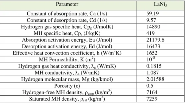
Chung et al. [65] used the MHT as shown in Figure 2.16, which is modeled as a two-dimensional symmetrical system. MHT is cylindrical in shape, and consists of 25 mm internal radius, 20 mm height, and 60 mm length. The tank has a lid with a 10 mm filter diameter for hydrogen gas inflow or outflow to the canister. It has a constant-temperature water bath containing heating/cooling fluid.
Figure 2.16. a) Geometry of MHT, b) Geometry of MHT used in the simulation [65].
Table 2.6 shows the properties of hydrogen and metal hydride, which are presented in a simulation study.
Table 2.6. The thermal-physical properties of metal hydride and hydrogen gas [65].
Parameter LaNi5
Constant of absorption rate, Ca (1/s) 59.19
Constant of desorption rate, Cd (1/s) 9.57
Hydrogen gas specific heat, Cpg (J/molK) 14890
MH specific heat, Cps (J/kgK) 419
Absorption activation energy, Ea (J/mol) 21179.6
Desorption activation energy, Ed (J/mol) 16473
Effective heat convection coefficient, h (W/m2K) 1652
MH Permeability, K (m2) 10-8
Hydrogen gas heat conductivity, λg (W/mK) 0.1815
MH conductivity, λs (W/mK) 1.087
Hydrogen molecular mass, Mg (kg/kmol) 2.01588
Porosity (ε) 0.5
Hydrogen-free MH density, ρemp (kg/m3) 7164
Saturated MH density, ρsat (kg/m3) 7259
Kaplan et al. [73] is modeled a 2-D metal hydride cylindrical tank through the control volume finite element method (CVFEM) as shown in (Figure 2.17), and Sakti et al. [63] is modeled the same geometry with finite element lab (FEMLAB). The system represents the experimental configuration of Kaplan et al. [73]. The MHT is a cylindrical-shaped tank that swaps heat through its external walls with the surrounding cooling fluid. The materials’ thermo-physical properties, concerned data, and computations have been exhibited in Table 2.7.
Table 2.7. The thermal-physical properties of metal hydride and hydrogen gas [73].
Parameter LaNi5
Density of LaNi5 (ρs) 4200 (kg/m3)
Hydrogen Density (ρg) 0.0838 (kg/m3)
LaNi5 Specific heat (Cps) 419(J/kgK)
Hydrogen - Specific heat (Cpg) 14,.890 (J/kgK)
Thermal conductivity of LaNi5 (λs) 1.2 (W/mK)
Hydrogen - Thermal conductivity (λg) 0.12(W/mK)
Porosity 0.55
Gas inlet temperature (T0) 293 K
Bed and wall - Initial temperature (Tf) 293 K
Coefficient of Heat transfer (h) 1652 (W/m2K)
Mohan et al. [40] used the MHT, as shown in Figure 2.18, which simulated the 2-D metal hydride formation in COMSOL Multiphysics. MHT is built in a cylindrical shape with many tubes and filters distributed inside the metal hydride. The cooling tubes are arranged in a triangular configuration inside the MHT and the filters are located at the center of each triangular arrangement. The center-to-center distance between the tubes (s) is called pitch distance. The LaNi5 alloy and hydrogen have
good thermo-physical properties, which are part of the simulation study (Table 2.8).
Table 2.8. The thermal-physical properties of metal hydride and hydrogen gas [40].
Parameter LaNi5
Density of LaNi5, ρs (kg/m3) 8200
Hydrogen Density, ρg (kg/m3) 0.0838
LaNi5 specific heat, Cps (J/kgK) 419
Hydrogen - Specific heat, Cpg (J/kgK) 14,890
Thermal conductivity of LaNi5, λs (W/mK) 1.2
Hydrogen - Thermal conductivity, λg (W/mK) 0.12
Porosity 0.55
Diffusivity of hydrogen, dg (m2/s) 4.6×10⁻¹²
Permeability, ḳ (m2) 10−8
Energy for Activation, Ea (J/mol) 21179.5
Constants (Ca) 59.187
hydride bed - Initial temperature, T0 (K) 293
Hydrogen inlet pressure, Pin (Bar) 8.0–15.0
Cooling media temperature, Tf (K) 293–323
Coefficient of overall heat transfer, h (W/m2K) 500–1500
Bed thickness, b (mm) 10–27.5
Cooling tube diameter, d2 (mm) 5–20
Ratio of container radius to pitch (r1/s) 3–7 (corresponding to N =31.163)
Figure 2.19. MHT modeling’s [74], and [62]. (a) Geometry used in modeling MHT-1 and (b) MHT-2.
The MHTs (Figure 2.19) are simulated for 2-D metal hydride formation in the COMSOL Multiphysics software. MHT is built using a cylindrical-shaped structure that swaps heat through its external walls (bottom and sides). A free space is left for metal hydride expansion after the absorption process (approximately 20% of the total volume). Aldas et al. [74]. The model was applied to two different cylindrical geometries with/without metal fins. Figure 2.19a shows the geometry used in
modeling MHT-1 (sub-domain 1: porous media, sub-domain 2: free space) and Figure 19b shows the geometry used in modeling MHT-2 (sub-domain 1: porous media, sub-domain 2: steel wall). Baldissin et al. [62]. The parameters used in the model computations are shown in Table 2.9.
Table 2.9. The parametric values used in modeling [62].
Parameter LaNi5
Initial temperature – absorption (T0) 294 K
Initial temperature – desorption (T0) 300 K
Initial pressure – absorption (P0) 19 bar
Initial pressure – desorption (P0) 2 bar
Initial hydride density (ρ0) 8300 kg/m3
Density of saturated hydride (ρss) 8354 kg/m3
Molecular weight of hydride (Ms) 426·10-3 kg/mol
Gas molecular weight (Mg) 2·10-3 kg/mol
Hydride specific heat (Cps) 355 J/kgK
Specific heat of gas (Cpg) 14890 J/kgK
Hydride porosity (ε) 0.5
Reaction enthalpy(∆H) -32600 J/mol
Reaction entropy(∆S) -104.5 J/mol K
Kinetic constant – absorption (Ca) 59.187 s-1
Kinetic constant – desorption (Cd) 9.57 s-1
Activation energy for absorption (Ea) 21179.6 J/mol
Activation energy for desorption (Ed) 16420 J/mol
Gkanas et al. [61] used the MHTs as shown in Figure 2.20, which are simulated as 3-D metal hydrides in COMSOL Multiphysics software. The model consists of three sub-domains: the perforated rectangular MHT (sub-domain 1), the cooling tubes (sub-domain 2), and the hydrogen channel (sub-domain 3). The model parameters have been shown in Table 2.10.
Table 2.10. The parametric values used in modeling [61].
Parameter LaNi5
Density of LaNi5 (ρs) 8300 (kg/m3)
Saturation hydride density (ρss) 8354 (kg/m3)
Density of Hydrogen (ρg) 0.0838 (kg/m3)
Hydride molecular weight (Ms) 432.45 (grams per mol)
LaNi5 specific heat (Cps) 355 (J/kgK)
Hydrogen - Specific heat (Cpg) 14,.890 (J/kgK)
Reaction enthalpy(∆Η) 30000 (J mol)
Reaction entropy(∆S) 104.7 (J/mol K)
Porosity 0.5
Coefficient of heat transfer (h) 400 (W/m2K)
Hydride conductivity (λ) 1.32 (W/mK)
Kyoung et al. [58] used the MHT (Figure 2.21), which is simulated for 3-D metal hydride formation in computational fluid dynamics (CFD). The MHT is built using a mesh configuration of a 3-D cylindrical shape. The thermo-physical properties and operating conditions used in computations have been mentioned in Table 2.11.
Table 2.11. The thermal-physical properties and operating conditions used in computations [58].
Parameter LaNi5
Saturated metal density, (ρs) 5369 (kg/m3)
Hydrogen-free metal density, (ρg) 0. 5300 (kg/m3)
LaNi5 specific heat (Cps) 0.419 (kJ/molK)
Specific heat of Hydrogen (Cpg) 14.890 (J/kgK)
Thermal conductivity of LaNi5 (ks) 1.04 (W/mK)
Hydrogen - thermal conductivity (kg) 0.167 (W/mK)
Porosity of the metal 0.63
Reference pressure, (Pref) 10 (bar)
Metal permeability (ḳ) 10−8m2
Activation energy, (Ed) 23.879.6 (J/mol)
Desorption rate constant, (Cd) 9.57 s-1
Initial temperature of hydride bed, (T0) 20 (oC)
Inlet pressure of hydrogen (Pin) 85 mbar
Heating temperature, (Th) 20 (oC)
Coefficient of heat transfer (h) 1652 (W/m2 K1)
In the Table 2.12 shows the summary of numerical investigations on the MHTs in literature
Table 2.12. Summary of numerical studies on MHTs.
Investigator/Date Geometry Used
Parameters Study Observations Mellouli [12]
2010
MHTs (Fig. 9)
The 2-D mathematical model is utilized using Fortran 90 to investigate the performance of MHST configurations and the influence of the fin geometry on hydriding process.
The storage time can be improved by 66% out of the time that 90% storage takes when circular fins are applied to enhance heat transfer in comparison with the situation, in which, fins aren’t used; therefore, good fin geometry is significant.
MHTs (Fig. 10).
The 2D mathematical modeling has been utilized using CVFEM for finding the effect of
the proposed
configurations and the results were compared with reported literature.
1- The thermal conductance is a key factor that transfers heat between the cooling fluid and the hydride material. 2- 80% improvement was
recorded in storage time with finned concentric heat exchanger tube.
Table 2.12. (continued)
Investigator/Date Geometry Used
Parameters Study Observations
3- Good agreement for experimental and numerical results was observed.
Mellouli [28] 2009
MHTs (Fig. 12).
The 2-D mathematical model is utilized using Fortran 90 to investigate the performance of MHST configurations and the impact of using aluminum foam.
1- Total 60% improvement was observed in the required time for 90% storage when aluminum foam was used. 2- Better performance of
MHST can be achieved by combining metal foam with concentric heat exchanger tube. Jemni [15,26] 1995 MHT (Fig. 11) The 2-D mathematical model is utilized using MFD for investigating the geometrical impact of the tank geometry under several operating conditions on the process of absorption/desorption of hydrogen.
1- The successful heat removal design reduces the hydrogen storing time by means of good choice of operating conditions such as inlet/outlet pressure and cooling/heating temperature. 2- The tank performance
improved by increasing the solid thermal conductivity and convection. Wang [66] 2012 MHT (Fig. 13). The 3-D mathematical model is utilized using Ansys Fluent for investigating the effect of thermal conductivity, tank geometry, and heat transfer of the stored hydrogen mass.
1- The aspect ratio of the tank (radius/height) has been observed in case of lower thermal conductivity and higher removal of heat. 2- MHT can perform better
using an active cooling system as compared to the natural convection when a substance is used for enhancing thermal conductivity. Freni [57] 2008 MHT (Fig. 14). The 3-D mathematical model is utilized using COMSOL to recognize the important factors, which lead to improve the MHST performance.
Hydrogen supply pressure, thermal conductivity, and permeability are the key factors to optimize the MHST performance. Freni [67] 2009 MHTs (Fig. 15). The 3-D mathematical model is utilized using COMSOL to investigate the performance of three MHST configurations.
1- The configuration with concentric tubes and additional cooling jacket that leads to the shortest charge time.
Table 2.12. (continued)
Investigator/Date Geometry Used
Parameters Study Observations
2- The metal hydride permeability and conductivity are the key factors to optimize the MHST performance. Chung [65] 2009 MHT (Fig. 16). The 2D mathematical modeling was utilized on COMSOL for evaluating the influence of the convection and expansion volumes.
The reaction rates reduced by the expansion volume. Heat convection performs a significant role once the expansion volume is included.
Kaplan [73] 2003
MHT (Fig. 17).
The 2D mathematical model is utilized with CVFEM to evaluate heat/mass transfer mechanisms.
The storage capacity is influenced by fluid flow and the results are very close to the reference values . Sakti [63] 2007 MHT (Fig. 17). The 2D mathematical model is utilized with FEMLAB to evaluate heat/mass transfer mechanisms.
The model successfully presents the hydriding behavior, which is similar to the one, which is available in the literature. Mohan [40] 2007 MHT (Fig. 18). The 2D mathematical modeling was utilized on COMSOL to evaluate influences of heat exchanger tubes with filters and several operating conditions, for example, heat transfer coefficient, pressure, and temperature.
The heat exchanger tube diameter with high MHST ratio and thickness of bed are major geometric parameters and offer good operating conditions.
Baldissin [62] 2009
MHTs (Fig. 19).
The 2-D mathematical model has been utilized with COMSOL to investigate the performance of MHST configurations.
Two tank geometries were examined and it was found that geometrical fins resulted in less temperature without fins (24ºC rather than 30ºC). Gkanas [61] 2013 MHTs (Fig. 20). The 3D mathematical modeling has been utilized applying COMSOL to investigate
the MHST
configurations.
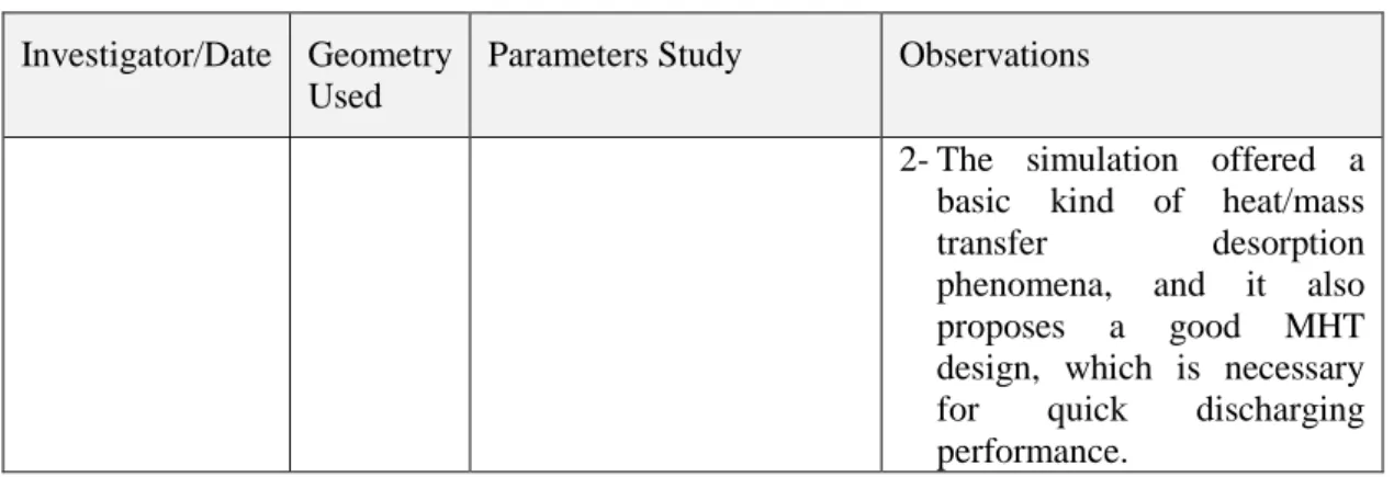
The ambient air can be perforated on a metal hydride tank, which increased the absorption/desorption systems. Kyoung [58] 2015 MHT (Fig. 21). The 3-D mathematical model is utilized with the help of CFD to investigate hydrogen desorption kinetics.
1- A good agreement was found between the calculated result and values reported in the literature.
Table 2.12. (continued)
Investigator/Date Geometry Used
Parameters Study Observations
2- The simulation offered a basic kind of heat/mass transfer desorption phenomena, and it also proposes a good MHT design, which is necessary for quick discharging performance.
2.1.3. MHT Design for Effective Heat Management
The proper design of MHT leads to a better hydrogen storage capacity. MHT, which has a better management of cooling design, confirms the shortest storing time [6,12, 15,26,28–31,33,36,40,53,54,57,58,61–63,65,66,67,69–71,73,]. In AB5-H2 system,
MHTs have been widely studied in different geometries and shapes in terms of hydrogen absorption/desorption, both experimentally and numerically in the literature. The sensitivity of several parameters have been studied and reported, including the MHT geometric design, configurations and/or the operating conditions are associated with hydriding process.
2.1.3.1. Influence of MHTs geometry and configuration
Heat transfer mechanism in hydriding reaction is strongly influenced by MHT geometries and configurations. The summary of experimental and numerical studies on MHT design in literature is shown in tables 2.1 and 2.12. In general, the literature studies confirmed that the high temperature created in the first stage of absorption is evident for exothermic reaction. Commonly, additional hydride is formed closer to the tank walls, as a result of cooling system. Since there is an argument in the literature that the hydrogen storage process requires heat transfer management, therefore, managing MHT heat transfer is needed to improve hydriding process. Accordingly, the next review showed various MHT designs taken from the previous studies. Jemni et al. [56] experimentally and theoretically inspected kinetic and
experimental outcomes and recognize that the model can be sufficiently used for hydriding. Askri et al. [31] showed reasonable agreement between the numerical and experimental results according to their findings and the reference values given in the literature (Jemni [56]). Optimization results also indicated that almost 80% development on storing time with finned concentric heat exchanger tube. Laurencelle et al. [19] confirmed the better MHT performance by using aluminum foam. Mellouli et al. [28] presented better performance of MHT that could be achieved by combining the concentric heat exchanger tube and the metal foam. Consequently, time efficiency 60% increased while storing 90% hydrogen. The results of simulation agree with the values reported in the literature by Laurencelle et al. [19]. Kaplan et al. [73] highlighted the fluid flow impact on capacity to store hydrogen and the results confirm the previous findings by Jemni [56]. Baldissin et al. [62] proved that the configuration with fins had lesser temperature in comparison with when no fins were added (24ºC rather than 30ºC). Gkanas et al. [61] claimed that ambient air is present in the tubes, which improves the performance of metal hydride tank and the processes such as absorption/desorption when a traditional rectangular MHT is used. Chung et al. [36] presented a novel design to clarify heat transfer mechanism in MHTs with/without adding a heat pipe. According to results, a finned heat pipe is a useful addition for enhancing capacity to store hydrogen. More than half time reduced in case of absorption process, and 44% of the time increased at 1L/min hydrogen desorption at 10bars atmospheric hydrogen supply pressure. Wang et al. [66] demonstrated the impact of the tank aspect ratio on heat removal and thermal conductivity. They believed that MHT performs better when an active cooling system is used rather than relying on natural convection as it actively increases the thermal conductivity. Dhaou et al. [70] experimentally investigated the absorption/desorption storing time of two MHTs, with and without cooper fins. The results depicted 75% increase in the storage capacity even in a shorter storage time, and this happened because of using a finned, spiraled, and coiled heat exchange system.
In literature, heat exchangers are considered as useful technical heat management devices as a part of the MHT design. In particular, employing finned spiral tubes embedded inside MHTs can result in important progress [12,28–30,68]. Kikkinides
![Figure 2.5. Geometrical configurations of MHT [53,71].](https://thumb-eu.123doks.com/thumbv2/9libnet/5391919.101700/28.892.174.802.919.1121/figure-geometrical-configurations-of-mht.webp)
![Table 2.2. Parametric values used in modeling [31].](https://thumb-eu.123doks.com/thumbv2/9libnet/5391919.101700/33.892.174.787.779.1077/table-parametric-values-used-in-modeling.webp)
![Table 2.3. The physical properties of the components used in modeling [28].](https://thumb-eu.123doks.com/thumbv2/9libnet/5391919.101700/35.892.160.782.312.733/table-physical-properties-components-used-modeling.webp)
![Figure 2.16. a) Geometry of MHT, b) Geometry of MHT used in the simulation [65].](https://thumb-eu.123doks.com/thumbv2/9libnet/5391919.101700/38.892.314.645.768.1081/figure-geometry-mht-b-geometry-mht-used-simulation.webp)
![Table 2.7. The thermal-physical properties of metal hydride and hydrogen gas [73].](https://thumb-eu.123doks.com/thumbv2/9libnet/5391919.101700/40.892.165.787.170.420/table-thermal-physical-properties-metal-hydride-hydrogen-gas.webp)
![Table 2.8. The thermal-physical properties of metal hydride and hydrogen gas [40].](https://thumb-eu.123doks.com/thumbv2/9libnet/5391919.101700/41.892.162.798.168.587/table-thermal-physical-properties-metal-hydride-hydrogen-gas.webp)
![Table 2.9. The parametric values used in modeling [62].](https://thumb-eu.123doks.com/thumbv2/9libnet/5391919.101700/42.892.164.795.317.748/table-the-parametric-values-used-in-modeling.webp)
![Table 2.11. The thermal-physical properties and operating conditions used in computations [58]](https://thumb-eu.123doks.com/thumbv2/9libnet/5391919.101700/44.892.165.796.184.547/table-thermal-physical-properties-operating-conditions-used-computations.webp)