Ri:. f· ,7 Vv '^; '?. •Í¿· 'C«ii iíí a it'vJ ‘iii^ if ii ’Ѵ.І» * .·Λ ^· ¡-/л ^ ?л ί\ ··? 3 r^?} «?** 'Tä »'■’·. ' ·> Í,·· ;> -^ ‘ί;, ·Μ ’;Í! ·.!* « ІМ* ¿ ' ^ І.М i ' # vW V w '-S»' Î. J »i '4^ i ¿ tSi <s l Í H t H Й i" 3 ■!' 'Я :· «<«. 4<,· 4. ij .. »a’· '«»· 4.І.1І .« W' * <«!·' • w '·ς^ W V Ч,' Iv: .-·.' w s* •гл - .">, , “;, r, ;' Г· 'У ·'■·- .■ ■*· Г' ?: · ,Гу tc»· ■i ■«[·> »... «'>.·;. '· Л* t. Д. ir/^j ,;.■ -Д •.'S ·-·. -.. ·· ^ f i · . ·· -<. • А В Л i B S B
ADAPTIVE SOURCE ROUTING AND
ROUTE GENERATION FOR
MULTICOMPUTERS
A THESIS
SUBMITTED TO THE DEPARTMENT OF COMPUTER ENGINEERING AND INFORMATION SCIENCE AND THE INSTITUTE OF ENGINEERING AND SCIENCE
OF BILKENT UNIVERSITY
IN PARTIAL FULFILLMENT OF THE REQUIREMENTS FOR THE DEGREE OF
MASTER OF SCIENCE
By
Yücel A y doğan July, 1995
II
I certify that I have read this thesis and that in my opinion it is fully adequate, in scope and in quality, as a thesis for the degree of Master of Science.
Assoc. Prof. C«ivdet Aykanat (Advisor)
I certify that I have read this thesis and that in my opinion it is fully adequate, in scope and in quality, as a thesis for the degree o f ,Master of Science.
Asst. Prof. Ilyas Çiçekli
I certify that I have read this thesis and that in my opinion it is fully adequate, in scope and in quality, as a thesis for the degree of Master of Science.
Asst. Prof. Tuğrul Dayar
Approved for the Institute of Engineering and Science:
'rot. MehmexBaray Director of the Institut
ABSTRACT
ADAPTIVE SOURCE ROUTING AND ROUTE
GENERATION FOR MULTICOMPUTERS
Yücel A y doğan
M .S . in Computer Engineering and Information Science Advisor: Assoc. Prof. Cevdet Aykanat
July, 1995
Scalable multicomputers are based upon interconnection networks that typi cally provide multiple communication routes between any given pair of proces sor nodes. In such networks, the selection of the routes is an important prob lem because of its impact on the communication performance. We propose the adaptive source routing (ASR) scheme which combines adaptive routing and source routing into one which has the advantages of both schemes. In ASR, the degree of adaptivity of each packet is determined at the source processor. Every packet can be routed in a fully adaptive or partially adaptive or non- adaptive manner, all within the same network at the same time. The ASR scheme permits any network topology to be used provided that deadlock con straints are satisfied. We evaluate and compare performance of the adaptive source routing and non-adaptive randomized routing by simulations. Also we propose an algorithm to generate adaptive routes for all pairs of processors in any multistage interconnection network. Adaptive routes are stored in a route table in each processor’s memory and provide high bandwidth and reliable in terprocessor communication. We evaluate the performance of the algorithm on IBM SP2 networks in terms of obtained bandwidth, time to fill in the route tables, and efficiency exploited by the parallel execution of the algorithm.
Keywords: Adaptive Routing, Multicomputers, Interconnection Networks, Par
allel Processing
ÖZET
Ç O K İŞLE M C İLİ B İL G İS A Y A R L A R D A U Y A R L A N A B İL İR K A Y N A K D A Ğ IT IM I V E Y O L Ü R E T İM İ
Yücel Aydoğan
Bilgisayar ve Enforaıatik Mühendisliği, Yüksek Lisans Danışman: Doç. Dr. Cevdet Aykanat
Temmuz, 1995
Olçeklenebilir çokişlemcili bilgisayarlar herhangi iki işlemci arasında birden fazla haberleşme yolu sağlayan bağlantı ağları üzerine kurulan sistemlerdir. Bu tür ağlarda yol seçimi haberleşme performansını etkileyen önemli bir etk endir. Uyarlanabilir Kaynak Dağıtımı (UKD), uyarlanabilir dağıtım ve kaynak dağıtımı yöntemlerini birleştiren ve her ikisinin de avantajlarına sahip olan bir dağıtım yöntemi olarak önerilmiştir. Her paket tam uyarlanabilir, kısmi uyarlanabilir yada uyarlamasız şekilde yöneltilir. UKD yöntemi kilitlenme sınırlamalarının sağlandığı herhangi bir ağ topolojisi kullanımına izin verir. Uyarlanabilir kaynak dağıtımı ve uyarlamasız rastlantısal dağıtım yöntemleri benzetim yapılarak karşılaştırılmıştır. Ayrıca çokişlemcili bilgisayar ağlarında işlemciler arasında uyarlanabilir yollar üreten bir yöntem önerilmiştir. Üretilen uyarlanabilir yollar her işlemcinin belleğindeki yol çizelgelerinde saklanır. Bu yöntem yüksek veri iletişim kapasitesi ve işlemciler arası güvenilir iletişimi sağlar. Önerilen yöntem ile IBM SP
2
çokişlemcisi ağları kullanılarak deneyler yapılmış ve sağlanan veri iletişim kapasitesi ve işlemcilerde yol çizelgesi oluşturma zamanları ölçülmüştür. Yöntemin çokişlemcili bilgisayarlarda par alel işlemesi ile elde edilen verim de deneysel olarak sunulmuştur.Anahtar Sözcükler: Uyarlanabilir Dağıtım, Çokişlemcili Bilgisayarlar, Bağlantı
Ağları, Paralel İşleme
ACKNOWLEDGEMENTS
I would like to express my deep gratitude to Dr. Bülent Abalı for his invaluable guidance, suggestion, and encouragement throughout the development of this thesis. I would like to thank my advisor Dr. Cevdet Aykanat for his guidance, suggestions, and contributions. I would like to thank Dr. Ilyas Çiçekli for reading and commenting on the thesis. I would also like to thank Dr. Tuğrul Dayar for reading and commenting on the thesis. I owe special thanks to Dr. Craig B. Stunkel at IBM T.J. Watson Research Center for providing figures for the thesis.
Bu çalışmamı
anneme ve bahama
adıyorum
Contents
1 Introduction 1
2 Adaptive Source Routing (ASR) 5
2.1
Adaptive Source Routing S c h e m e ...6
2.2
The Matching of Packets and Outputs ...8
2
.2.1
Maximum Matching P r o b l e m ... 82
.2.2
Maximum Matching H eu ristic... 92.2.3 Performance of Maximum Matching H e u r is tic ...
11
3 Simulation of Adaptive Source Routing 13 3.1 The Switch A rch itectu re... 13
3.2 The Network ... 15
3.3 The Sim ulator... 16
3.3.1 Packet G en era tor... 17
3
.3.2
Control of Packet Flow in the N e tw o rk ... 193.4 The Routing Schemes in the S im u la to r...
22
3.4.1 Random R o u t in g ...
22
3
.4.2
Adaptive R ou tin g...22
3.5 Simulation R e s u l t s ... 23
4 Route Generation in Multicomputers 25 4.1 Route Table G en era tor... 26
4.1.1 Routability between P r o c e s s o r s ... 29
4
.1.2
Generating All Adaptive R o u te s ... 314.1.3 Selection of an Optimal R o u t e ... 34
4.2 IBM SP2 Network A rch ite ctu re... 36
4
.2.1
The Switch C h i p ... 374.2.2 IBM SP2 Network T o p o lo g y ... 39
4.3 Route Generation in SP2 N e tw o rk s... 40
4.3.1 An Example Route Generation ... 40
4.3.2 Adapting the Algorithm to SP
2
Networks ... 444.3.3 Experimental R esu lts... 44
4.3.4 An Improvement in the Algorithm ... 45
4.4 Parallel Route Table G e n e r a to r ... 47
4.4.1 Experimental R esu lts... 49
5 Conclusion 52
A Simulation Results of ASR 54
B IBM SP2 Network Examples 60
List of Figures
2.1
Message Packet Form at...6
2.2
A bipartite graph and its m a tc h in g ...8
2.3 The Matching Heuristic ... 9 2.4 A request matrix R and finding the maximum matching . . . .
10
2.5 A bipartite graph with S{G) =
2
...12
3.1 Maximum matchings for some of the possible request matrices for 2 X 2 sw itch es... 14
3.2 Request matrices for 2 x 2 switches for which the maximum matchings may c h a n g e ... 15 3.3
8
x8
Benes n e t w o r k ... 163.4 Function defined for generating an inter-arrival time between two successive packets using Poisson distribution... 18
3.5 Algorithm used for generating packets into the network at an arbitrary t i m e ... 19
3.6 Algorithm of packet flow control during one clock cycle. Move ments of all packets in the network during one clock cycle is handled by this algorithm...
20
3.7 Algorithm for the network simulator ... 21
4.1 Route Table G en erator... 27
LIST OF FIGURES
4.2 Generating routes from a processor to other p r o c e s s o r s ... 28
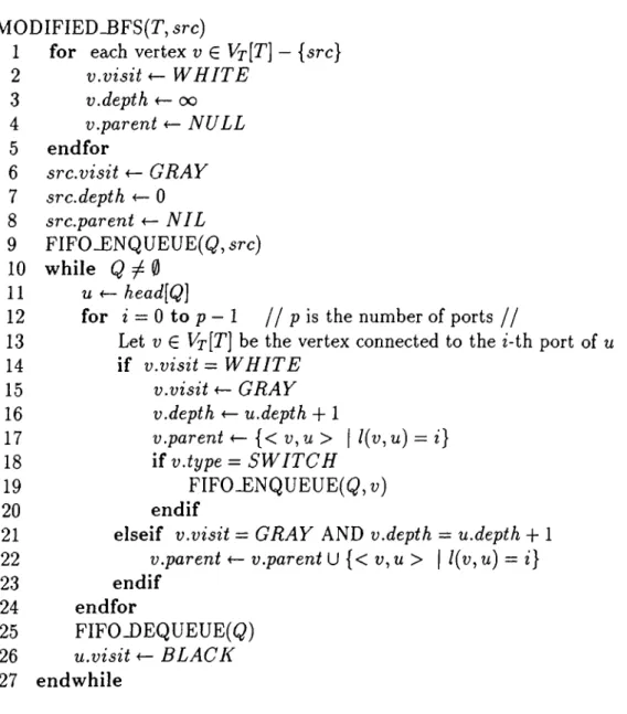
4.3 Modified Breadth First Search algorithm. The algorithm finds all shortest paths from a source processor node to other proces sor nodes in a topology graph... 30
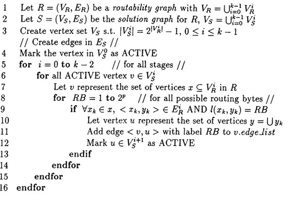
4.4 The algorithm for generating the solution graph S = (V
5
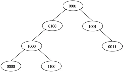
, Es) for a routability graph R = {Vr, Er) ... 324.5 Example digital search tree... 33
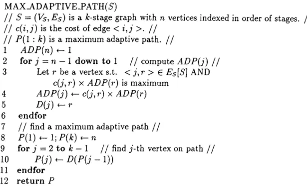
4.6 Algorithm for determining maximum adaptive path in a A:-stage multistage graph S = (V
5
, Es). It also constructs and returns the maximum adaptive path... 364.7 The Switch chip organization. Courtesy Dr. Craig. B. Stunkel, IBM T.J. Watson Research Center... 37
4.8 The Switch Board consisting of
8
Switch Chips (an SP2
frame) .39
4.9 SP2 48 way system interconnection... 404.10 A 32 node SP
2
network... 414.11 i? = (Vfl, Eß) for processor pair (4,30) ... 42
4.12 S = {Vs, Es) for processor pair ( 4 ,3 0 ) ... 43
4.13 A parallel algorithm for generating routes at a processor to other processors in the network... 48
4.14 Speedup graph for parallel route table generator... 50
4.15 Efficiency graph for parallel route table g e n e ra to r... 51
A .l Performance of adaptive source routing and non-adaptive ran dom routing on a 16 X 16 network with uniform communication p attern ... 55
A .2 Performance of adaptive source routing and non-adaptive ran dom routing on a 32 X 32 network with uniform communication pattern ... 55
LIST OF FIGURES
XI
A.3 Performance of adaptive source routing and non-adaptive ran dom routing on a 64 X 64 network with uniform communication
p a ttern ... 56
A .4 Performance of adaptive source routing and non-adaptive ran dom routing on a 128x128 network with uniform communication p attern ... 56 A .5 Performance of adaptive source routing and non-adaptive ran
dom routing on a 512x512 network with uniform communication p attern ... 57 A
.6
Performance of adaptive source routing and non-adaptive random routing on a 16 X 16 network with shift-right communica
tion p a t t e r n ... 57
A .7 Performance of adaptive source routing and non-adaptive ran dom routing on a 32 X 32 network with shift-right communica
tion p a t t e r n ... 58 A
.8
Performance of adaptive source routing and non-adaptive random routing on a 64 X 64 network with shift-right communica
tion p a t t e r n ... 58 A .9 Performance of adaptive source routing and non-adaptive ran
dom routing on a 128 x 128 network with shift-right communi cation p a tte rn ... 59
A. 10 Performance of adaptive source routing and non-adaptive ran dom routing on a 512 x 512 network with shift-right communi cation p a tte rn ... 59
B . l A 128 node network consisting of
8
first stage and 4 second stage switch boards. Courtesy Dr. Craig. B. Stunkel, IBM T.J. Watson Research Center... 61 B.2 A 256 node network consisting of 16 first stage and 16 secondstage switch boards. Courtesy Dr. Craig. B. Stunkel, IBM T.J. Watson Research Center... 61
List of Tables
2.1
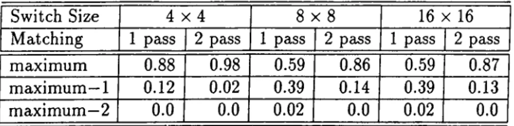
Performance of the matching heuristic. Percentage of the time a maximum, or a maximum—1
, or a maximum—2
matching is found...12
3.1 Throughput under uniform and non-uniform packet traffic . . . 23
4.1 Average adaptivity for different sized networks ... 44
4.2 Average route table generation times for one p r o c e s s o r ...45 4.3 Average route table generation times for one processor for the
improved algorithm ... 46 4.4 Statistics for parallel route table g e n e ra to r... 50
Chapter 1
Introduction
Scalable multicomputers are based upon interconnection networks that typi cally provide multiple communication routes between any given pair of pro cessor nodes. Interconnection networks [
2
, 7] can be classified according to their topology. A static network topology is one that does not change after the machine is built. Ring, star, mesh, and hypercubes are some of the examples for static interconnection topologies. Parallel computers employing static in terconnection networks can have very good performance on specific problems to which their network topologies are well matched. However, it is hard to achieve a multipurpose highly parallel system using a fixed interconnection topology short of an all-to-all network. This difficulty has given rise to much work on dynamic interconnection networks. Bus networks, multistage switch ing networks, and crossbar networks are examples for dynamic interconnection topologies. A bus network is very much like a party-line telephone. A crossbar network, on the other hand, is like a private exchange that allows any processor to contact any other non busy processor at any time. A multistage switching network falls in between these two extremes.Multiple routes provided by interconnection networks and routing algo rithms play important role in providing low latency, high bandwidth, and re liable interprocessor communication. Examples of interconnection networks used in commercial machines are the IBM SP2 multistage interconnection net work [1, 27], Cray T3D
3
-dimensional torus [12
], and the Connection Machine fat tree [4, 16].Given an interconnection network, a distance measure D can be defined on it. A routing algorithm is said to be minimal [
22
] if for every sequence of nodesCHAPTER 1. INTRODUCTION
Go, such that they conform a feasible path from gq to Ok, it holds that
D{ai,ak) > D(aj,ak) if i < j , i.e., every hop brings the message closer to its
destination.
A routing algorithm is adaptive if for some pair of nodes a, b it can use more than a path when routing messages from a to b. Note that not only must these paths exist physically, but the routing algorithm must be able to make use of them. The choice of the path to be taken by a particular message may depend on many factors, e.g., faulty links or congestion in the network. Minimal fully adaptive algorithms do not impose any restrictions on the choice of shortest paths to be used in routing messages; in contrast, partially adaptive minimal routing algorithms allow only a subset of available minimal paths in routing messages. The well known e-cube [5] algorithm is an example of non-adaptive routing algorithms [5,
6
] since it has no flexibility in routing messages.Usually, two kinds of routing algorithms are defined. In packet switching routing, the messages are of constant size and they are called packets. In this kind of routing, packets are moved from node to node. If the messages are of variable size, wormhole routing can be used instead. In wormhole routing, a message m is divided into a sequence of constant size flits. The first flit (the head) of the sequence must hold the destination’s address because it is used to determine the path the message must take. Once a link is occupied by the head, it cannot be used for other messages until the last flit of m has left it. If the head of m discovers that the next link it has to traverse is being used, it must wait in the buffers until the link is freed.
Adaptive routing schemes are employed in some networks to eliminate con
gestion by finding alternate routes to destinations [3, 4,
6
, 13]. On the other hand, some networks trade off performance for simplicity of switch design be tween flexible choice of topology by employing non-adaptive routing schemes such as the source routing scheme used in SP2
[1
, 27]. In the source routing scheme, the packet route is deterministic and it is completely determined at the source processor sending the packet. In the first part of this thesis, we propose the adaptive source routing (ASR) scheme which combines adaptive routing and the source routing to exploit the advantages of both schemes. In ASR, the degree of adaptivity of each packet is determined at the source processor node. Every packet can be routed in a fully adaptive, or partially adaptive, or non-adaptive manner, all within the same network at the same time. AdaptiveCHAPTER 1. INTRODUCTION
source routing is a superset of the source routing scheme used in IBM SP
2
mul ticomputer, thus ASR is backward compatible with the SP2
routing scheme. The ASR scheme also permits any network topology to be used provided that deadlock constraints are satisfied, unlike other adaptive routing schemes.The ASR scheme has the advantages of both adaptive routing and source routing schemes as it combines both. However, the problem we address when we make use of adaptivity is the assignment of outputs to the packets in the switches. The switch must -adaptively and in a conflict free manner- assign an output to each packet from a set of permitted outputs specified in the packet header, with the consideration that multiple packets may be waiting for an output assignment. This problem can be formulated as a maximum matching
problem in a bipartite graph [19, 23, 28]. Polynomial time algorithms exist for
solving maximum matching problem [19, 23] however these algorithms require sophisticated data structure that are difficult and impractical to implement in switch hardware. We propose a maximum matching heuristic that can be implemented in terms of primitive logic operations AND, OR, NOT, and Rotate which makes it possible to implement in switch hardware.
The performance of the ASR scheme is evaluated by a network simulator. We describe the network simulator and present the experimental results of simulations on a sample network. We compare the ASR scheme with non- adaptive random routing scheme by giving the average latency as a function of average load in the network for different sized networks.
The second part of this thesis is on route table generation for multicom puters based upon any interconnection network. Packets in interconnection networks that have a regular structure, make use of the regular structure in the interconnection topology to determine the possible ports that lead the packet to correct destination at each stage. The main disadvantage of such networks is the restriction on the number of processors that can be connected to maintain the interconnection structure. The requirement is that the number of processors should generally be a power of 2. IBM SPl and SP
2
multicom puters make use of multistage interconnection networks that provides a wide flexibility in the number of processors connected because of the interconnect technology used. However such networks need not have any structure in the interconnection topology which complicates route decision at each stage.CHAPTER 1. INTRODUCTION
We propose an algorithm for route generation in any multistage intercon nection network regardless of the regularity in the topology. Generated routes for each pair of source-destination processors are adaptive routes that provide multiple distinct paths and are stored in a route table in each processor’s mem ory. We implemented and evaluated the performance of the proposed algorithm on IBM SP
2
[26] interconnection networks. The SP2
switch architecture and the network implementations are introduced. The experimental results show how much the generated adaptive routes make use of the physically existing paths with the execution times on different sized networks. We also give an improvement in the algorithm and the results of the improvement. The parallel version of the proposed algorithm is also presented.The organization of the thesis is as follows: we describe the proposed adap tive source routing scheme and the maximum matching heuristic in a bipartite graph in Chapter
2
. The network simulator and the simulation results of ASR on a sample network are given in Chapter 3. The proposed route generation al gorithm for any interconnection network and experimental results on IBM SP2
network samples with the parallel route generation algorithm are presented in Chapter 4. Finally, conclusions are given in Chapter 5.
Chapter 2
Adaptive Source Routing (ASR)
In adaptive routing networks, message packets make use of multiple paths between source-destination node pairs [
6
]. Switches alleviate the congestion problem by sending packets from less busy alternate routes. For example, a busy output port will cause an adaptive routing switch to use another output port in routing a packet to its destination. This means that the adaptive routing switch must know which of its outputs lead to the intended destination. For this reason, a common requirement for all adaptive networks is a regular, simply described network topology such as a hypercube, mesh, ¿-ary n-cube, or a fat tree [3, 4,6
, 13, 16]. The switches then have an implicit knowledge of the topology, and therefore can route packets using shortest paths. For example, in a2
-dimensional mesh topology, each switch knows that a node at the upper right corner of the network can be reached by sending a packet either in the North or East direction. In an alternative approach, routing tables may be put in each switch, however this would be impractical since it would occupy valuable real-estate on the switch chips.In the source routing scheme, unlike adaptive routing, switches need not know the topology; the source processor determines the route and encodes the routing information in the packet header, which is then used by the switches. Thus, switches make routing decisions purely based on local information. For example, in the SP
2
multistage network, which consists of8
x8
switches [27], the packet header for an n-hop message initially contains 3-bit routing bytesRi, R2, .. ■, Rn as shown in Fig.
2
.1
. Each routing byte indicates a switch port numbered from 0 to 7. The source processor determines the route and putsCHAPTER 2. ADAPTIVE SO URGE RO UTING (ASR)
LENGTH
Ri
Rn
DATAI
DATAk
Figure
2
.1
. Message Packet Formatrespective bytes in the header. As the message packet proceeds in the net work, each switch examines the first byte and forwards the packet through the indicated output port. The switch also strips off that first byte before forward ing the packet to the next level in the network. Thus the packet contains no routing information upon arriving at its destination. In SP
2
, routing bytes are computed only once and then kept in a route table in each processor node. Keeping route tables in processors is inexpensive since processors already have large memory. The algorithm for creating the routing tables is described in [1
]. The route table approach enables routing to be done in a topology independent fashion which is important in practice. Any network topology is possible to implement without having to change the hardware or the routing algorithms, provided that cost, performance, and deadlock constraints are satisfied. Fur thermore, faulty links and switches are handled easily by modifying routing tables. In that respect, source routing is more flexible than adaptive routing.2.1
Adaptive Source Routing Scheme
In the adaptive source routing scheme proposed in this thesis, the packet format is similar to that of SP
2
. However, each routing byte indicates a set of possible output ports, rather than a specific output port. Each m -bit byte has the format R = rm-i^m-2
· · · ^0
) where m is the number of switch ports. One bits indicate the set of outputs that the switch is permitted to route the packet through. Routing header is determined by the source processor sending the message packet, as in source routing. Each switch examines the first byte and adaptively selects from one of permitted outputs by considering the local traffic, and then forwards the packet to the next level in the network. The switch also strips off that first byte before forwarding the packet as in source routing. For example, in a network constructed of8
x8
switches such eis in SP2
, a packet header may consist of bytes Ri =00001111
, i?2
=11000000
, R3
=01000000
, which tells to the first switch that the packet may be routed through one ofCHAPTER 2. ADAPTIVE SO URGE RO UTING (ASR)
the four ports 0-3, and to the next switch that through one of the ports
6
, 7, and to the last switch that through the port6
. Thus, the number of distinct paths a packet may follow from source to destination is^path = |7?l| X W X X |77„_i| X |7?„| (2.1)
where |i?,| is defined as the number of ones in the routing byte 72,·. Obviously
Npath paths must exist between the source and destination, and any combina
tion of the outputs specified in the header must correctly lead the packet to its destination. In Chapter 3 of the thesis, we describe only the switch archi tecture and simulations of the proposed routing scheme. The algorithms we proposed for determining routing headers for multistage interconnection net works will be described in the later chapters and the experimental results on SP
2
interconnection networks are also presented.Each source processor can determine the degree of adaptivity of each mes sage packet by varying TVpath· If .A^path =
1
, then the adaptivity is zero; the packet is to be routed through a single deterministic path. This case is equiv alent to the routing scheme used in SP2
[27]. Furthermore, TVpath = 1 case may be useful for several other applications. When interprocessor communi cation patterns are known in advance, optimal route between each processor pair may be selected to minimize congestion. A heuristic for solving that op timization problem is described in [1
]. When operating in the SIMD mode such that permutations to be realized by the network are known in advance, single deterministic routes may be selected. A/path =1
Ccise may also be use ful for diagnosis of the interconnection network, where faulty links or switches are to be determined; for example a source processor may identify faulty el ements by circulating packets through deterministic paths. If Apath = max, then the adaptivity is maximum and packets may reap performance bene fits of full adaptivity. This case is useful when some switches get congested due to non-uniform message traffic and difficult communication patterns. If1
< Apath < max, then each packet is routed in a partially-adaptive manner, where only a subset of all possible paths is utilized. This case may be useful when the network is to be logically partitioned among multiple parallel tasks so that their respective communications do not influence each other; using the ASR scheme, each packet may be forced to remain in its partition, however routed in a fully adaptive manner within the partition.CHAPTER 2. ADAPTIVE SO URGE RO UTING (ASR)
IN
OUT
0
1
Figure 2.2. A bipartite graph and its matching
2.2
The Matching of Packets and Outputs
In this section, we address the problem of assigning outputs to the packets. Each packet in a switch has a set of permitted outputs specified in the packet header leading the packet to its destination in an adaptive manner. The switch must assign an output to each packet considering the permitted set of outputs. The switch must also consider that multiple packets may be waiting for an output assignment. The assignment of outputs to packets must be adaptive and conflict free. This problem can be formulated as a maximum matching
problem in a bipartite graph [19, 23, 28].
2.2.1
Maiximum Matching Problem
A graph G{V\^ V2, E) is called a bipartite graph if its vertex set V is the disjoint union of sets Vi and V
2
, and every edge in E has the form (vi, U2
)) where vi € Vi and V2 € V2
. If G{Vi, V2,E ) is a bipartite graph, a matching in G is a set ofedges in G such that no two edges share a vertex. A maximum matching in G is defined as the matching that has as many vertices in Vi as possible with the vertices in V
2
·The problem of matching outputs to packets can be formulated as a max imum matching problem as follows. Let G { I N , O U T , E ) be a bipartite graph with a set of vertices IN, OUT, and a set of edges E. Each vertex in I N represents a packet waiting to be assigned an output. Each vertex in OUT represents an output. Each edge in E represents a permitted output assign ment specified in the routing byte of the packet. Let M be the set of edges in
CHAPTER 2. ADAPTIVE SO URGE RO UTING (ASR)
a matching in G. In maximum matching problem, we try to maximize the car dinality of M, i.e., the number of successful output assignments in our case, so that the message bandwidth through the switch is maximized. Fig. 2.2 shows an example bipartite graph where the matching is maximum.
Note that a matching scheme is also described for the Chaos router in [13, 14]. Our scheme differs in that we try to maximize matching, whereas in their scheme, packets are assigned without consideration for the other packets waiting in the switch. Their justification was that for the hypercube topology they considered, only one packet would be in the switch even under heavy traffic conditions.
MATCH(i?,passes)
1 Let M be an m X m matrix representing the
matching, and M, denote the ¿-th row of M, Let i? be an m X m matrix representing the request
matrix, and Ri denote the ¿-th row of R, Let C be an m -bit row vector
2
Initialize M using R3
for A; =1
to passes 4 for ¿ = 0 to m — 15
C *— Colum nO R (M )6
C ^ C OR ~Ri7 Mi ^ R otateJJntil.Z ero{M i,C )
8
en d for9 en d for 10 return M
Figure 2.3. The Matching Heuristic
2.2.2 Maximum Matching Heuristic
Polynomial time algorithms exist for solving the maximum matching prob lem [19, 23]. However, these algorithms require sophisticated data structures which would be difficult to implement in hardware. Here, we describe a heuris tic that can be implemented in terms of primitive logic operations AND, OR,
CHAPTER 2. ADAPTIVE SO URGE RO UTING (ASR)
10
(a)
(b)
0 1 2 3
0
1 2 3
- ► 0
0)
10 0
0
-0
10 0
1
0
0 1 0
1
10
0
0
2
0
1 0 1
2
0
10
1
3 0
0
0
13 0
0
0
1OF
I 1 10 0
OF
1 11 0
(C)(d)
0
1 2 3
0
12 3
0
rv
1 0 0
0
10 0
1
1
0 (
D
0
11 0
I0
0
-^2
1 1 0 (
0
2
1
10 (
0
3 0 fD 0
1- ► 3
0 (
0
0
1 o fI 1 1 1 1
o fI 1
1 11
Figure 2.4. A request matrix R and finding the maximum matching
NOT, and Rotate.
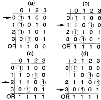
The set of packets waiting for an assignment is represented by an m x m binary request matrix R as shown in Fig. 2.4(a), where m is the number of outputs. Matrix R is constructed from packets’ routing bytes. Each row of R corresponds to a packet, and each column corresponds to an output. One bits in a row indicate the set of outputs that the respective packet may be routed through. An m X m binary output assignment matrix M is defined such that
each row of M comprises at most
1
one bit. A one bit Mij in M indicates that output j is assigned to packet i for routing. By definition M should have one bits only at places where R has one bits. In Fig. 2.4(a), the M matrix is superimposed over i?, indicated by circled one bits of R. A Colum nOR operation on M is defined such that M 's rows are ORed column-wise, whose m -bit result C gives the set of assigned outputs (ones) and unassigned outputs (zeros) for the given M matrix. An operation called RotateJJntil-Zero{M i, C ) is defined on m -bit row vectors Mi and C such that the one bit in Mi is aligned to a zero bit in C7, i.e.. Mi is rotated until the result of M,· A N D C is all zeros. Using the primitive operations defined, the heuristic shown in Fig. 2.3 attempts to find a maximum matching. The heuristic starts with an arbitrary matching Af, then for each row Mi [i =0
,1
, . . . , m —1
), it does Colum nOR on M finding unused outputs, and then rotates Mi to an unused output with the condition that i?,· (the routing byte) has a one in that column position.CHAPTER 2. ADAPTIVE SO URCE RO UTING (ASR)
11
Fig. 2.4(a)-(d) illustrates the procedure: in step (a) Mo cannot be rotated because there is no permitted free output. In step (b) Mi is rotated to output 2. In step (c) M2 is rotated to output 3, resulting in a maximum matching since no free outputs are left. In step (d) no change is made.
The heuristic doesn’t find a matching in the strict sense because it may assign multiple packets to the same output. In that case, we assume that the switch will employ some fair arbitration policy to choose one of those packets for routing. Note that the cardinality of the matchings found by the heuristic is monotonically increasing; in each step a better solution is found or there is no change. Note also that the heuristic does not always find a maximum matching. However, at the expense of increased execution time, the procedure may be repeated few more times to improve the solution (the variable passes is the repeat count). The number of repetitions for finding the maximum matching depends on the request instance and there is not a bound on the number of repetitions that will yield the maximum matching.
2.2.3
Performance of Maximum Matching Heuristic
We evaluated the performance of the matching heuristic on pseudo-randomly generated request matrices R. To be able to evaluate how good the matching found by the heuristic is, we must determine the cardinality of the maximum matching that is possible in a bipartite graph G. We use the idea in [8] to determine the maximum number of vertices that can be matched in a bipartite graph as follows. Let G = (Vi,V2, E ) be a bipartite graph. H A Ç 14, then
6{A) = \A\ — |i?(y4)|, where R{ A) is the subset of V2 consisting of those ver tices that are adjacent to the vertices in A^ is called the deficiency o f A. The
deficiency o f graph G, denoted 6{G), is given by S(G) = max{ 6{ A) \ A C Vi}.
The following theorem, proved in [8], gives the cardinality of the maximum possible matching in a bipartite graph.
T h e o r e m 2.1 Let G = (1 4 ,
14
, E) be a bipartite graph. The maximum numbero f vertices in 14 that can be matched with those in V2 is |V4| — 6{G). Moreover,
a matching o f size |I4| — 6{G) exists.
To illustrate the theorem, consider the bipartite graph in Fig. 2.5. Note that ¿ ({a , 6, d }) = 2 and this is maximum, so S(G) = 2. So \X\ — S(G) = 4 — 2 = 2.
CHAPTER 2. ADAPTIVE SO URGE RO UTING (ASR)
12
Figure 2.5. A bipartite graph with S(G) = 2
The largest subset of X that can be matched has two elements. An example of such a set is { a, c } .
We generated a number of request matrices for the heuristic and compared the matching found by the heuristic with the possible maximum matching given by Theorem 2.1. Table 2.1 shows that the heuristic finds a maximum matching over
88
% of the time using one pass and 98% of the time using two passes for4
x 4 switches. For8
x8
and 16 x 16 switches, our matching heuristic finds a maximum matching over86
% of the time using two passes. It is worth noticing that the percentage of finding a maximum—2
matching is very low (2
%) using one pass and is 0% using two passes. So the matching found by the proposed heuristic is either a maximum matching with a very high probability or a maximum—1
matching with a considerably low probability.Implementation of the heuristic in terms of primitive logic operations AND, OR, NOT, and Rotate makes it possible to implement the heuristic algorithm in switch hardware unlike the algorithms for solving maximum matching problem which require sophisticated data structures.
Switch Size 4 x 4
8
x8
16 X 16Matching
1
pass2
pass1
pass2
pass1
pass2
passmaximum
0.88
0.98 0.590.86
0.59 0.87maximum
—1
0.12
0.02
0.39 0.14 0.39 0.13maximum
—2
0.0
0.0
0.02
0.0
0.02
0.0
Table
2
.1
. Performance of the matching heuristic. Percentage of the time a maximum, or a maximum—1
, or a maximum—2
matching is found.Chapter 3
Simulation of Adaptive Source
Routing
In Section
2.1
we described the adaptive source routing (ASR) scheme. We developed a network simulator for evaluating the performance of the ASR scheme and we present the simulation results. In this chapter we introduce the switch architecture used in the network simulator. We present the algorithm for the simulator and describe how packets are generated to be able to simulate different message traffic and load in the network. Simulation results are given at the end of the chapter.3.1
The Switch Architecture
In the simulations we used
2
x2
switches. The switch consists of a buffer at each input and output port, and a2
x2
crossbar interconnecting input buffers to output buffers. The main operation of the switch is to forward the packets in the input buffers to the output buffers in a profitable manner. The unit of transfer between the buffers is a packet. A cycle is defined here as the time required for a packet to move from one buffer to another. In each cycle, either a forwarding or a blocking operation takes place. In forwarding, a packet moves forward entirely from an input buffer to the assigned output buffer in a switch or through the links between the switches i.e., from an output buffer of a switch to the input buffer of the connected one. In blocking, a packet is blocked in the buffers waiting for the availability of the buffer it is assigned to. The 2 x 2 size of the crossbar in the switch simplifies the matching heuristic described inCHAPTER 3. SIMULATION OF ADAPTIVE SOURCE ROUTING
14
(a) 0 1 (b) 0 1 (C) 0 1 (d) 0 1 0 0 0 0 0 0 0 0 ( l ) 0 ® T 1 0 ® 1 ® 0 1 0 0 1 0 0(e)
(f) (g) (h) 0 1 0 1 0 1 0 1 0 ® 1 0 0 A ® 0 1 0 ® 1 ® 0 1 1 1 ® (i) (j) 0 1 0 1 0 0 : i ) o 1 : 1 ) 0 1 0 ®Figure 3.1. Maximum matchings for some of the possible request matrices for
2
x2
switchesSection
2
.2.2
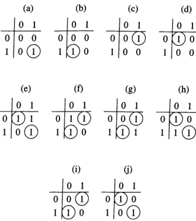
considerably; routing decision is made by a table lookup since the number of possible cases is small, and the matchings are always the maximum. The set of packets waiting for an assignment is represented by a 2 x2
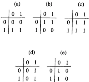
binary request matrix (see Fig. 3.1). Each row of the request matrix corresponds to a packet, and each column corresponds to an output. One bits in a row indicate the set of outputs that the respective packet may be routed through. The assignment matrices are superimposed over the request matrices in Fig. 3.1, indicated by circled one bits. Some entries of the table used to make the assignment of outputs to packets are in Fig. 3.1. In these request matrices, the packets’ permitted set of outputs make it possible to make a maximum matching of outputs to packets in a deterministic way. The assignment for each case for obtaining a maximum matching of outputs to packets is unique and straight forward. However, assignments in the remaining entries of the table are not unique. The switch must make a decision considering the local traffic and the starvation problem of some packets. These entries are in Fig.3
.2
. When only one packet is waiting for an eissignment, as in Fig. 3.2(a)-(b), twoCHAPTER 3. SIMULATION OF ADAPTIVE SOURCE ROUTING
15
(a)
(b)
(c)
0
1
1
0 1
0 1
0
0 1 1
0 1 1
1
1 0 0
1 1 1
(d)
(e)
0 1
0 1
0 0 1
0 1 0
1 0 1
1 1 0
Figure
3
.2
. Request matrices for2
x2
switches for which the maximum match ings may changedifferent assignments can be made. The switch decides which output to assign to the packet according to the local traffic i.e., the available output buffer is assigned to the packet. In case both output buffers are available, the output buffer is chosen in a round robin fashion for uniform distribution of packets to all links and switches in the network. There may be conflicting requests of output buffers. More than one packet may demand the same output buffer as in Fig.
3
.2
(d )-(e). These conflicts are resolved in a round robin fashion to prevent starvation of some packets. Fig.3
.2
(c) shows the case that all the packets are permitted to use all output buffers. In this case, a maximum matching is found according to the available output buffers resolving the conflicts among the packets in a round robin fashion.3.2
The Network
In the simulations, we used the Benes interconnection network since it has been extensively studied for synchronous and asynchronous communication [7], and since it is a multistage network which provides multiple paths between source- destination pairs as in the SP
2
interconnection network. Although, Benes networks are generally considered for synchronous communication in SIMD machines with a centralized network control [2
], here we will consider it for asynchronous communication in MIMD machines with a distributed networkCHAPTER 3. SIMULATION OF ADAPTIVE SOURCE ROUTING
16
0
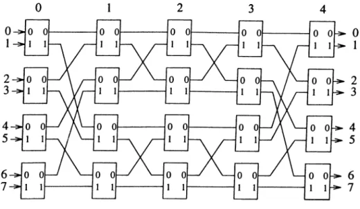
Figure 3.3.
8
x8
Benes networkcontrol, such that each switch makes its own routing decisions, as described in Section
2
.1
. An A'’ input N output Benes network consists of2
(Iog A^)—1
stages o f switches interconnected as shown in Fig. 3.3 for N — 8. The Benes network may be viewed as concatenation of a baseline network B ( N ) that consists of stages0
,1,2
in Fig. 3.3, and its mirror image B~^{N) that consists of stages 2,3,4 in Fig. 3.3, with the middle stage (stage2
) shared between B { N ) andB~^(N). This construction is well known. The N x N Benes network provides N/2 different paths between any given input-output port pair as explained
in the following. In the baseline network B{ N) , there is a single path from a given input to a given output. From a given input of the Benes network,
N/2 different switch inputs in the middle stage of the Benes network may be
reached, and from that point there exists a single path to reach the required network output. Therefore, there exists N/2 different paths between any given input-output port pair in the Benes network.
3.3
The Simulator
We implemented a network simulator which simulates the behavior of adaptive source routing and non-adaptive random routing schemes under different loads using a number of communication patterns. The simulator has two major components which are the component for controlling the insertion of packets into the network and the component for controlling the flow of packets in the
network. These two major components, their functions, and algorithms are given in the following sections. The main algorithm used in the simulator is defined just after the following two sections.
3.3.1
Packet Generator
CHAPTERS. SIMULATION OF ADAPTIVE SOURCE ROUTING
17
In order to be able to evaluate the performance of a routing scheme, we must provide different communication patterns and different loads to the network. These are the functions of the packet generator.
Packet destinations for uniform communication pattern are randomly gen erated at each input port to reach to every output with a uniform distribu tion. The packet generator also allows generating packet destinations for a number of structured communication patterns like cyclic-shifi-left communi
cation, cyclic-shift-right communication, and reverse communication patterns.
In cyclic-shift-left communication pattern, the destination for the packet is cal culated by shifting the binary representation of the source processor sending the packet one bit position to the left in a cyclic manner. For example, in an 8 X 8 Benes network, processor
6
(110 in binary) sends packets to processor 5 (101 in binary). The cyclic-shift-right communication pattern is similar. For the preceding example, processor
6
(110
in binary) sends packets to pro cessor 3 (Oil in binary). In reverse communication pattern, the sum of the source and destination processors must sum up to —1
in an iV x TV net work. For the8
x8
Benes network example, processor6
sends packets to1
and processor
1
sends packets to6
. These are the uniform and some examples of the structured communication patterns implemented. Packet generator also permits implementation of packet destination calculations for other structured communications in a very modular way, by just describing the relationship between the source processor sending the packet and the receiving processor.In addition to providing different communication patterns, the packet gen erator must also provide a way to generate packets at random time instants such that the inter-arrival times between successive packets are in control of the user to provide different loads to the network in simulations. We gener ate packets at random instants with geometric inter-arrival times using the
probability density function (pdf) 1 — a
X a
CHAPTER 3. SIMULATION OF ADAPTIVE SOURCE ROUTING
18
POISSON(a)
1 Let random{) return a real number
between
0.0
and1.0
with uniform distribution2
r ^ ( l — a ) x random{)3 i < - (log r - log((l - a )/a )) / logo 4 retu rn (int)i
Figure 3.4. Function defined for generating an inter-arrival time between two successive packets using Poisson distribution
where 0 < a < 1. This function satisfies the property that all probabilities sum up to
1
, i.e.,A
1
- aX ; --- x o ‘ = l (3.2)
t=i ^
a is the parameter for the distribution function which determines the inter
arrival times of the randomly generated packets. This distribution is known as the Poisson distribution [24]. The algorithm used to generate a time interval for the next packet to be inserted in to the network is in Fig. 3.4. Note that a simpler exponential random number generator [
20
] can also be used.The relationship between the poisson distribution function parameter a and the average inter-arrival time between successive packet generation, t, is given by the equality
t = 1
1
— a (3.3)For example, for a = 0.5, the average inter-arrival time between two successive packets is
2
time units. In fact this means that if function POISSON(0.5) is repeated enough number of times, the average of the values returned by the function equals2
.We described how to determine the time instants to generate the next packet arrival into the network. All the processors must insert packets into the network at random instants using the defined algorithm. This is achieved by keeping the time to generate the next packet in each processor, which we call Packet JssueTTime. Our simulator is clock driven and a global clock is used. Packet JssueJTim e for each processor is initialized at time 0 by using poisson distribution function in Fig. 3.4 which determines the time for the first
CHAPTERS. SIMULATION OF ADAPTIVE SOURCE ROUTING
19
PACKET_GENERATION_PROCESS(A^, a)1
forI
=0
to —1
2 if C L O C K = PacketJssueJTim e[i] 3 In sert-P a ck et JntoJVetwork(i) 4 C ollect-Statistic${)5 P acket JssueTTime[i] <— Packet J ssu eJ rim e[i]+ POISSON(a)
6 endif
7 endfor
Figure 3.5. Algorithm used for generating packets into the network at an arbitrary time
packet to be generated for each processor. The algorithm used for determin ing which processors will inject packets into the network at an arbitrary time is given in Fig 3.5. The function In sert-P a ck etJ n to.N etw ork (i) creates a packet at the source processor i, determines the destination processor accord ing to one of the communication patterns used as described at the beginning of Section 3.3.1, and places the generated packet into the source processor’s buffer to be delivered to the destination processor. C ollectjStatisticsQ is the function used for collecting statistics like the number of packets generated at each input processor, the average inter-arrival times of packets, and current load in the network.
3.3.2
Control of Packet Flow in the Network
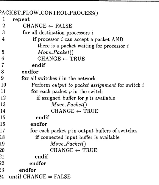
Our network simulator is derived by a global clock. The packets in the network are forwarded towards destination or blocked waiting for the needed buffers to be available during each clock cycle. The operations of packet propagation or blocking during one clock cycle are controlled by the algorithm given in Fig. 3.6. M oveJPacket{) moves the packet from one buffer to the destination buffer. Whenever a movement of a packet occurs denoted by the variable CHANGE, the loop is iterated since the buffer emptied by the packet may accept a packet waiting for it. The loop terminates when there are no more possible moves of packets in the network. The order of the processors or the switches processed does not affect the result of this algorithm.
CHAPTER 3. SIMULATION OF ADAPTIVE SOURCE ROUTING
20
PACKET-FLOW .CONTROL_PROCESS()
1 repeat
2 CHANGE FALSE
3 for all destination processors i
4 if processor i can accept a packet AND there is a packet waiting for processor i
5 M ovt-P a ck etQ
6
CHANGE TRUE7 endif
8 endfor
9 for all switches i in the network
10 Perform output to packet assignment for switch i
11 for each packet p in the switch
12 if assigned buffer for p is available
13 M ov e.P a ck et{)
14 CHANGE ^ TRUE
15 endif
16 endfor
17 for each packet p in output buffers of switches
18 if connected input buffer is available
19 M ove-P a ck et{)
20 CHANGE <- TRUE
21 endif
22 endfor
23 endfor
24 until CHANGE = FALSE
Figure 3.6. Algorithm of packet flow control during one clock cycle. Movements of all packets in the network during one clock cycle is handled by this algorithm.
CHAPTERS. SIMULATION OF ADAPTIVE SOURCE ROUTING
21
NETWORK_SIMULATOR(A^, M A X .P A C K E T S , a)
1
Let M A X -P A C K E T S be the total number of packets to be inserted into the network for simulationLet a be the Poisson distribution parameter for network load 2 Initialize processor and switches using the network
topology description file {N x N network) 3 fo r i = 0 to —
1
4 P acket JssueL rim e[i] <— POISSON(a)
5 e n d fo r
6
C L O C K^ 0
7 r e p e a t8
if P A C K E T S J N -N E T W O R K < M A X -P A C K E T S 9 PACKET.GENERATIONJ"ROCESS(A^, a) 10 PACKET_FLOW.CONTROL_PROCESS()11
C L O C K ^ C L O C K V l12
e n d if 13 un til P A C K E T S J N -N E T W O R K = M A X -P A C K E T SAND all packets are delivered to their destinations
Figure 3.7. Algorithm for the network simulator
We described how the packets are inserted into the network and how the packet moves are controlled in the simulator. The main algorithm of the sim ulator is as in Fig. 3.7 using the defined algorithms. Initialization of the in stants o f first packet generation for each processor are performed in lines 3-5 o f Fig. 3.7. Generation of packets into the network and the control of the packet moves are iterated until a given number of packets are inserted in the network and all packets in the network are delivered to their destina tions. When the number of packets generated reaches the given constant, PACKET_GENERATIONJPROCESS() stops generating new packets. Deliv ery of all packets in the network to their destinations is signaled by the avail ability o f all input and output buffers of all switches in the network.
CHAPTER 3. SIMULATION OF AD A PTIVE SOURCE ROUTING 22
3.4
The Routing Schemes in the Simulator
3.4.1
Random Routing
We implemented a random routing scheme based on the ideas described in [
6
] for comparison with ASR. Random routing has been devised to reduce conges tion that may occur in the network when communication patterns are highly structured. In this scheme, the packet is first routed to a randomly chosen intermediate destination, and from that destination the packet is routed to its final destination. Here, we use this idea in the following way: suppose a packet is to be routed from input a to output b of the Benes network. We first route the packet from a to a randomly chosen middle stage input of the Benes network. From that middle stage input we route the packet to6
. There exists a single path to accomplish this task and therefore the random routing scheme is non-adaptive.3.4.2
Adaptive Routing
In the ASR scheme, we encode routing headers such that packets are routed in a fully-adaptive manner in the first (log A^) —
1
stages of the network (stages 0 and1
in Fig. 3.3). That is the first (log A^) —1
bytes of the packet’s routing header consists of all ones indicating all output ports in the first (logA^) —1
stages lead the packet to its destination. Once the packet reaches an input of the middle stage (stage 2 in Fig. 3.3), there exists a single path to reach to the required network output. Therefore, the packet will be routed in a non- adaptive manner in the last log N stages of the network. For computing routing bytes in the last logA^ stages, the destination-tag method is used [
2
]. In this method, the destination port number in binary,6
„ _ i6
„_2
. . . ¿»oj indicates the switch ports that should be used to reach to the required network output. The first switch routes the packet through its port numbered6
„_ i, the next switch through bn- 2 and so on. For example in Fig. 3.3, to reach from any input of stage2
to network output6
(110
in binary), the packet must be routed through port1
of a switch in stage 2, then through port1
of a switch in stage 3, then through port 0 of the switch connected to output6
in stage 4.CHAPTER 3. SIMULATION OF ADAPTIVE SOURCE ROUTING 23
3.5
Simulation Results
Simulation results of the adaptive source routing scheme and the non-adaptive random routing scheme for different network loads and communication patterns are presented, giving the average latency as a function of the average load.
Latency is defined as the number of cycles that takes a packet to cross the
network. Latency includes queuing delays at the source processor. Load is defined as the average number of packets injected to an input port of the network per cycle.
1.0
packet/cycle (100
% load) is the upper bound for the Benes network. For both routing schemes, we used identical seeds for the pseudo-random number generators. We ran simulations until at least 1500 packets were generated at each input port. The latency of the delivered packets in a network having only a small population (packets currently in the network), do not reflect the exact behavior of latency in terms of load. Packets are deli vered to their destinations without queuing delays and blocking when the network is initially clear of packets. For this reason, various statistics were gathered starting from the time the network population has reached a steady state. The number of packets that reached their destinations and that are currently in the network are controlled at each clock cycle to determine whether the network population is in a steady state or not. Whenever the packets in the network reach a predetermined amount, the network population is said to be in a steady state.Network
UNIFORM NON-UNIFORM
Adaptive Non-adaptive Adaptive Non-adaptive
16 X 16 0.48 0.40 0.58 0.40
32 X 32 0.46 0.38 0.53 0.37
64 X 64 0.44 0.37 0.55 0.36
128 X 128 0.43 0.37 0.51 0.34
512 X 512 0.41 0.35 0.50 0.34
Table 3.1. Throughput under uniform and non-uniform packet traffic
In the simulations, uniform loads were used; equal loads were applied to every network input. Figures A .l through A.5 in Appendix A show the simu lation results under uniform packet traffic. Packet destinations were randomly generated at each input port to reach to every output with a uniform distribu tion. Figures A
.6
through A. 10 show the simulation results using a structuredCHAPTERS. SIMULATION OF ADAPTIVE SOURCE ROUTING
24
communication pattern, cyclic-shift-right communication. This communica tion pattern introduces a non-uniform packet traffic in the network. Packet destinations were generated as described in Section 3.3.1. Table.
3.1
gives the throughput of random routing scheme and the adaptive source routing scheme under uniform and non-uniform packet traffic in the network. The adaptive routing scheme increases the throughput by a factor of 18% on the average un der uniform packet traffic. When the packet traffic is non-uniform, the increase in the throughput that adaptive source routing provides is about 45% on the average as expected. Another noteworthy observation is that the throughput decreases with increasing network size.Chapter 4
Route Generation in Multicomputers
Scalable multicomputers are based upon interconnection networks that typi cally provide multiple communication routes between any given pair of proces sor nodes. Multiple routes provide low latency, high bandwidth, and reliable interprocessor communication. There are multistage interconnection networks (MIN’s) [18, 25] which have a regular structure, such as Omega [15], Banyan [
9
], and indirect binary n-cube [21] networks. Using the inherent knowledge of the interconnection topology, each switch in the network knows which output ports lead a packet to its destination at each stage. Route generation for such net works makes use of the structure in the topology to determine possible output ports to reach to the destination at each stage of the network. An example is the Benes network given in Section3
.2
. In an x Benes network, all output ports in the first (log A ) —1
stages lead the packet to its destination. For the last log A stages, the network provides a deterministic route for each destination processor, determined by the destination-tag method.Regular structure in the interconnection topology of the network provides easy route generation. However a common restriction for such networks is the number of processors that can be connected. Number of processors must generally be a power of 2. This requirement restricts the scalability of the mul ticomputer in terms of the processors and the interconnection network. The only possible amount of increase in the number of processors in an A proces sor network is N. Besides, the interconnection network must also be scaled according to the structure in the interconnection topology. Thus, any upgrade in the size of the parallel system will necessitate large amount of funding. These disadvantages have given rise to research on interconnection networks