CMUT Array Element in Deep-Collapse Mode
Selim Olcum
1, F. Yalcin Yamaner
2, Ayhan Bozkurt
2, Hayrettin K¨oymen
1, and Abdullah Atalar
1 1Bilkent University, Electrical and Electronics Engineering Department, Ankara, Turkey
2
Sabanci University, Electronics Engineering, Istanbul, Turkey
Abstract— Collapse and deep-collapse mode of operations have boosted the pressure outputs of capacitive micromachined ul-trasonic transducers (CMUTs) considerably. In this work, we demonstrate a CMUT element operating in the deep-collapse mode with 25 V pulse excitation and without the effects of charge trapping. The fabricated CMUT element consists of 4 by 4 circular cells with 20 µm radius and 1 µm thick plates suspended over a 50 nm cavity. The overall size of the element is 0.190 mm by 0.19 mm. The collapse voltage of the plates is measured to be approximately 3V. By driving the CMUTs with 25V pulses in the deep-collapse mode without any bias, we achieved 1.2 MPa peak-to-peak pressure output on the surface of the CMUT element with a center frequency of 9 MHz and 100% fractional bandwidth. We applied 1000 consecutive electrical pulses with alternating polarity to the element and witnessed no change in the transmitted acoustic pulse.
I. INTRODUCTION
Output power limitations of capacitive micromachined ultra-sonic transducers (CMUTs) have been one of the obstacles in front of the commercialization efforts, since ultrasound imag-ing applications require sufficiently high amplitude pressure waveforms transmitted into the target medium. A higher ampli-tude of the pressure waveform translates into more penetration depth and a better signal-to-noise ratio. It has recently been shown in [1] that it is possible to transmit high amplitude pressure pulses using the deep-collapse mode of CMUTs. The deep-collapse mode of operation requires voltages well above the collapse voltage of the transducer to be applied between the its electrodes. In this mode, CMUTs are designed to have very low collapse voltages and generating high amplitude pressure pulses does not require very high voltages. We show that it is possible to generate high amplitude pressure pulses using no bias and relatively low voltage levels that can be generated by a high-voltage CMOS process1.
For most CMUT geometries, a dielectric insulation layer made from silicon oxide or silicon nitride is used between the transducer electrodes to provide electrical isolation. This layer sets the minimum electrode separation in the collapse-mode, which in turn determines the limit on the electrical attraction force applied on the plate. A thinner insulation layer is preferable to increase electrical force applied on the plate. However, a thin dielectric layer may pose a charge trapping problem when it is subject to high electric fields [2]. The charge trapped in the insulation layer may degrade the device performance by creating a counter-force. In this paper, we
1For example, H18 (0.18µm up to 50V) and H35 (0.35µm up to 120V)
processes of Austria Microsystems AG, Unterpremst¨atten, 8141, Austria.
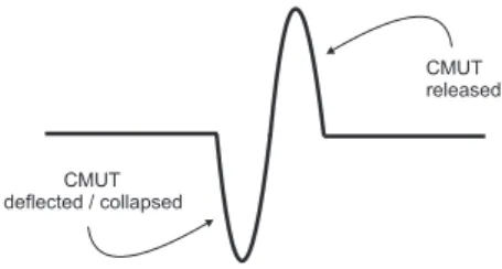
Fig. 1. An ideal pressure pulse in time generated by a CMUT, when a voltage pulse excitation is applied between CMUT electrodes.
propose a simple way to eliminate the effects of the charge trapping without compromising the output pressure level.
We first discuss the movement of the CMUT plate during the electrical pulse excitation. We use this discussion to determine the optimal electrical pulse shape to be applied to a CMUT during the deep-collapse mode. Finally, we demonstrate the deep-collapse mode of operation at relatively low voltage levels without the detrimental effects of the charge trapping.
II. ELECTRICALPULSE
An ideal pressure waveform generated by a CMUT in response to an applied voltage pulse is shown in Fig. 1. It consists of two parts: a negative pressure cycle and a positive pressure cycle. The negative pressure cycle is generated by the deformation of the suspended plate towards the substrate due to the rising edge of an applied voltage pulse. The positive pressure cycle is generated by the release of the CMUT plate due to the falling edge of an electrical excitation.
A. Pulse amplitude
By Coulomb’s Law, the electrical attraction force generated between the plates of a parallel plate capacitor is proportional to the square of the applied voltage across its electrodes. Hence the amplitude of the negative pressure cycle increases quadratically with the increasing pulse amplitude. The positive pressure cycle is generated by the restoring force of the deformed plate2. Since the collapsed state benefits greatly from higher voltages, the excitation voltage should be as high as possible. In many real-life applications the available voltage from the transducer driver is limited. With integrated driver circuits, this limit can be as low as 50 Volts. In this paper we assume a maximum peak-to-peak input voltage (VP) of 50V.
2It was demonstrated previously in [1] that the restoring force of a plate
increases drastically in the collapsed state.
108
978-1-4577-1252-4/11/$26.00 ©2011 IEEE 2011 IEEE International Ultrasonics Symposium Proceedings 10.1109/ULTSYM.2011.0027
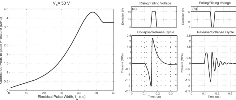
Fig. 2. Effect of the electrical voltage pulse width on generated peak-to-peak pressure amplitude when CMUTs are driven with a 50V electrical pulse. The simulated CMUT cells have 40 µm radius, 2 µm thickness, 100 nm gap and 100 nm of insulation layer. 19-cell array element is assumed. Rise and fall times of the electrical pulse are 5 ns.
B. Rise and fall times of excitation
We investigate the electrical pulse as a combination of two consecutive step voltages: a rising step and a falling step. If a rising step voltage is applied to a CMUT, the plate deflects from its initial rest position towards the substrate and comes to a stationary position, where the electrical attraction force and the restoring force of the plate are equalized. The attraction forces are the highest at the equilibrium point due to decreased electrode separation. With a falling step voltage, the plate moves back to its initial position. The restoring force of the plate is maximum at the beginning of the motion and becomes zero when the plate comes to a rest. During both movements, the net force exerted to the immersion medium is the difference of the electrical attraction and mechanical restoring forces. To achieve the maximum force to be exerted to the medium at all times, the transitions of the electrical excitation must be as short as possible. This condition is more critical in the case of the falling step voltage, since the restoring force of the plate is maximum at that point in time.
C. Pulse width
During repetitive pressure pulse firings, the rising and falling step voltages follow each other and generate identical pressure pulse waveforms. A rising step voltage followed by a falling step voltage generates a pressure waveform similar to that in Fig. 1. However the delay, tw, between the step voltages
affects the pulse shape and pressure amplitude significantly. During the rising step voltage, the plate accelerates due to the increasing electrical attraction force with decreasing electrode separation. Due to the inertia of the plate, there is an overshoot in the position of the plate beyond the equilibrium point.
Fig. 3. Pressure generated by a simulated CMUT as a function of time, when the CMUT is excited by (a) an electrical pulse (collapse/release) and (b) inverted electrical pulse (release/collapse). Rise and fall times of both electrical pulses are chosen to be 10 ns. The simulated CMUT has 40 µm radius, 2 µm thickness, 100 nm gap and 400 nm of insulation layer thickness.
The falling step voltage must be applied at the instant when the maximum deflection is achieved in order to achieve the maximum swing in the plate deflection.
The effect of the pulse width on the peak-to-peak pressure amplitude is given in Fig. 2 when a CMUT is excited by 50 Volts electrical pulses. The presented results are achieved by equivalent circuit simulations. The details and accuracy of the equivalent circuit model used in this paper can be found in [3]. The equivalent circuit model is terminated by the radiation impedance of a 19-cell array element which is calculated in [4]. The figure shows that there is an optimal pulse width to achieve a pressure waveform with the highest amplitude.
D. Pulse shape
Up to this point we assumed that all the electrical excitations applied to CMUTs are in the shape of an uninverted pulse, i.e., a rising step voltage followed by a falling step voltage with a delay of tw as in Fig. 3(a). Alternatively, an inverted
pulse can be applied to CMUTs by changing the order of the rising and the falling step voltages. In Fig. 3, two different pressure waveforms are depicted obtained by driving a 19-cell CMUT array element with uninverted and inverted pulses with optimum pulse width. The optimum pulse width for an inverted pulse is not the same as that for an uninverted pulse. During the falling voltage step, the stored mechanical energy is radiated into the medium as a positive pressure waveform. The plate is accelerated by high restoring forces and the force acting on the plate decreases as the plate is released. Once the plate transfers all of its energy to the medium its velocity drops. Therefore a damped pressure
Fig. 4. An optical micrograph of a fabricated CMUT element: 16 cells (4 by 4) each with a radius of a=20 µm and a cell to cell separation of 10 µm. The aperture size of the element is 0.19 mm by 0.19 mm and the fill factor of the cells is 56%.
waveform is transmitted into the medium. As mentioned already, an uninverted pulse generates an overshoot beyond the equilibrium point resulting in an underdamped waveform. This extra energy due to overshoot would result in higher acoustic pressure levels for an uninverted pulse. An uninverted pulse would result in about 3 dB higher pressure waveform compared to an inverted excitation pulse, even after the pulse widths are independently optimized.
III. EXPERIMENTALRESULTS
We demonstrate the deep-collapse mode of operation using a CMUT array element consisting of 16 cells (4-by-4) as shown in Fig. 4. For the production of the transducer, the microfabrication process used in [1] is utilized. We used a patterned gold bottom electrode layer on a silicon substrate in order to mimic the case in a real application with a CMOS compatible fabrication process. Fig. 4 depicts a micrograph of the fabricated CMUT element consisting of 4 × 4 cells with 20 µm radius and 1 µm thick plates. Each cell has 10 µm spacing with the neighboring cells resulting in a fill factor of approximately 56%. The cells are measured to have a collapse voltage of approximately 3 Volts.
We performed immersion experiments in an oil tank using a calibrated hydrophone ONDA HGL-0200. All the electrical excitations are in the form of an uninverted pulse voltage similar to that in Fig. 3(a). The electrical signals are applied to CMUTs using a commercially available pulse generator (Agilent 8114A). The rise and fall times of the excitations are measured to be around 15ns in the worst case. For voltage pulses with different amplitudes, the pulse widths are optimized to get the maximum pressure output from the
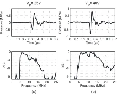
Fig. 5. Transmitted pressure waveforms by the fabricated CMUT array element with (a) 25V and (b) 40V pulse excitations. The pressure spectra of the transmitted waveforms are given below.
CMUT element. The optimum pulse widths are measured to be 38ns and 22ns for 25V and 40V pulse excitations, respectively. The recorded hydrophone signal is corrected with respect to attenuation and diffraction losses as in [1], and the generated pressure at the surface of the CMUT element is calculated. The resulting pressure waveforms at the surface of the CMUT element are given in Fig. 5. The dip around 10MHz is due to the energy lost to the silicon wafer substrate, which can be prevented by a proper backing or thinning the wafer. We achieved pressure waveforms with 1.2MPa and 1.6MPa peak-to-peak amplitude, respectively on the surface of the CMUT element with 100% fractional bandwidth. The center frequencies are 9MHz and 11MHz, respectively. The center frequency shift due to the increasing pulse amplitude was studied in the context of the collapse mode earlier in [5]. Both 25V and 40V electrical excitations force the CMUT plate with a collapse voltage of ∼3V to go into deep-collapse, resulting up to∼50 kPa/V large signal transmission efficiency.
In this paper, we showed that using the deep-collapse mode it is possible to achieve pressure amplitudes up to 1.6 MPa using a voltage amplitude of 40V. We should note here that the experimental results presented in this paper does not constitute a higher limit on the mode. No optimization was performed on the device dimensions, gap height, and element dimensions.
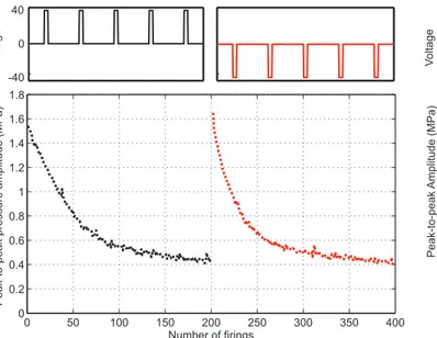
The charge trapping for the deep-collapse mode, on the other hand, is quite important and is a major setback for a repeatable operation. As the CMUT goes into deep-collapse and comes back, charge traps in the insulation layer. The counter-acting effect of the trapped charges can be observed on the transmitted pressure amplitudes over time as shown in Fig. 6. The pressure amplitude drops to half of its maximum value after about 50 firings due to charge trapping. After the voltage polarity is switched to negative after 200 firings, the trapped charge acts constructively with the electrical pulse
Fig. 6. Peak-to-peak amplitude of the transmitted pressure pulses by the fabricated CMUT element as a function of firings for 200 consecutive positive polarity voltage pulse excitations followed by 200 negative polarity voltage pulse excitations. The pulse magnitude is kept at 40V.
excitation for the first few firings. Therefore, as soon as the pulse polarity is switched the amplitude of the generated pressure waveform abruptly increases and starts to decrease immediately due to the charge trapping with the opposite polarity.
We utilize an alternating pulse scheme in order to decrease the effect of the charge trapping to a minimum while still driving the CMUTs in deep-collapse mode and maintaining high amplitude pressure pulses at the output. In Fig. 7 the polarity of the electrical excitation is switched after every consecutive firing. There is no sign of charge build up in the insulation layer after one thousand firings. However, a driver circuit like this would require twice the voltage margin. Nevertheless, the 25V case in Fig. 7 is suitable for a circuit with a maximum voltage of 50V. Using 25V alternating polarity voltage pulses, it is possible to generate 1.2 MPa pressure pulses at the output of the CMUT element without any degradation in the transmitter performance due to charge trapping.
IV. CONCLUSIONS
In this paper, we demonstrate a CMUT array element operating at 9MHz with 100% fractional bandwidth. We drive the element with no bias and alternating polarity 25V electrical pulses which can be generated by integrated driver circuits of a 50V CMOS process. Using 25V pulses it is possible to drive the CMUTs into deep-collapse and generate pressure pulses up to 1.2MPa peak-to-peak. In addition, alternating pulse scheme prevents the effects of the charge trapping in the insulation layer, enabling long term, repeatable operation. We believe that it is possible to fabricate reliable CMUTs that will operate in the deep-collapse mode using today’s commercial microfabrication technologies.
Fig. 7. Peak-to-peak pressure amplitude of the transmitted pressure pulses by the fabricated CMUT element as a function of the alternating polarity voltage pulse excitations. The experiment is repeated for electrical pulses with different magnitudes.
ACKNOWLEDGEMENTS
This work was supported by TUBITAK under the project grant 110E216. S.O. gratefully acknowledge the financial support of TUBITAK and ASELSAN A.S¸. for their National Scholarship and Ph.D. Fellowship Programs, respectively. A.A.acknowledges the support of TUBA.
REFERENCES
[1] S. Olcum, F. Y. Yamaner, A. Bozkurt, and A. Atalar, “Deep collapse operation of capacitive micromachined ultrasonic transducers,” IEEE
Trans. Ultrason., Ferroelect., Freq. Contr., vol. 58(11), 2011.
[2] S. Machida, S. Migitaka, H. Tanaka, K. Hashiba, H. Enomoto, Y. Tadaki, and T. Kobayashi, “Analysis of the charging problem in capacitive micro-machined ultrasonic transducers,” in Proc. IEEE Ultrason. Symp., 2008, pp. 383–385.
[3] S. Olcum, F. Y. Yamaner, A. Bozkurt, H. K¨oymen, and A. Atalar, “An equivalent circuit model for transmitting capacitive micromachined ultra-sonic transducers in collapse mode,” IEEE Trans. Ultrason., Ferroelect.,
Freq. Contr., vol. 58(7), pp. 1468–1477, 2011.
[4] A. Ozgurluk, A. Atalar, H. K¨oymen, and S. Olcum, “Radiation impedance of an array of circular capacitive micromachined ultrasonic transducers in collapsed state,” in Proc. IEEE Ultrason. Symp., 2011.
[5] ¨O. Oralkan, B. Bayram, G. G. Yaralioglu, A. S. Ergun, M. Kupnik, D. T. Yeh, I. O. Wygant, and B. T. Khuri-Yakub, “Experimental characterization of collapse-mode CMUT operation,” IEEE Trans. Ultrason., Ferroelect.,
Freq. Contr., vol. 53, pp. 1513–1523, 2006.


