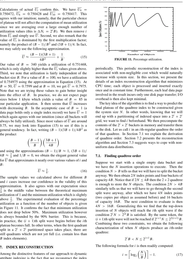
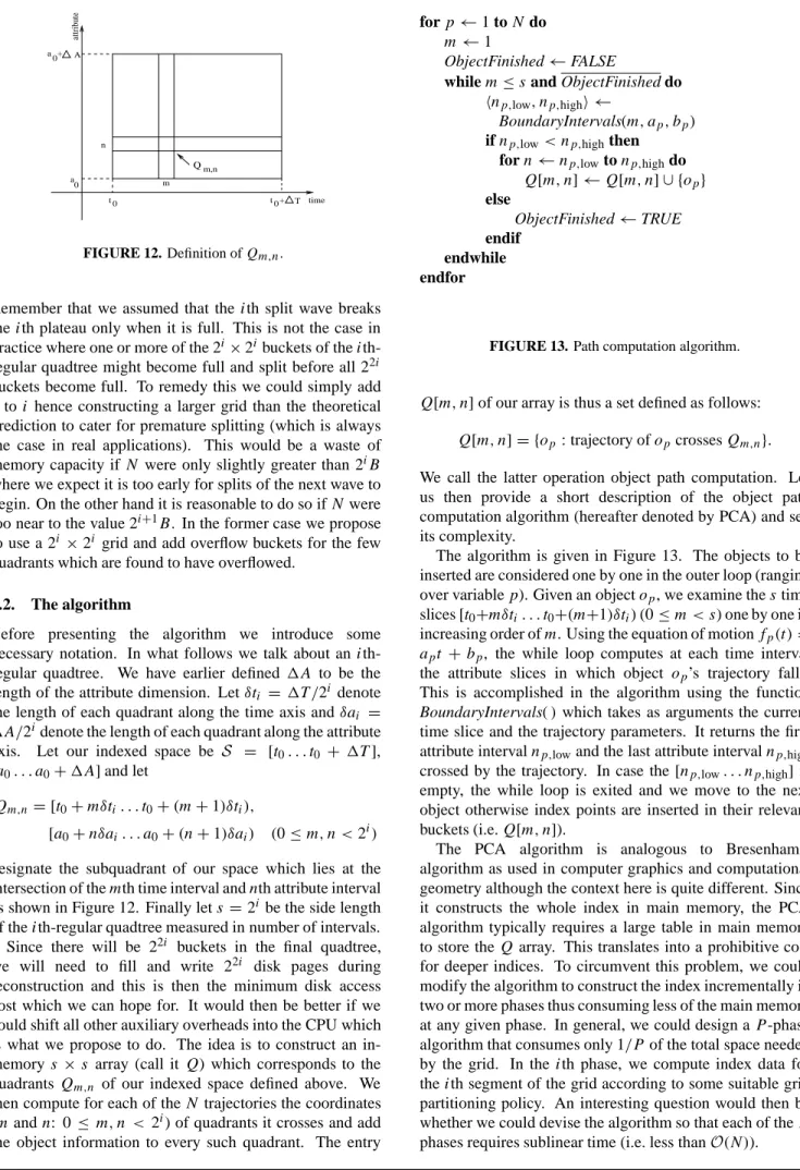
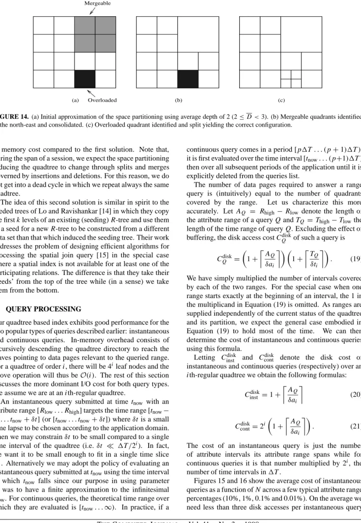
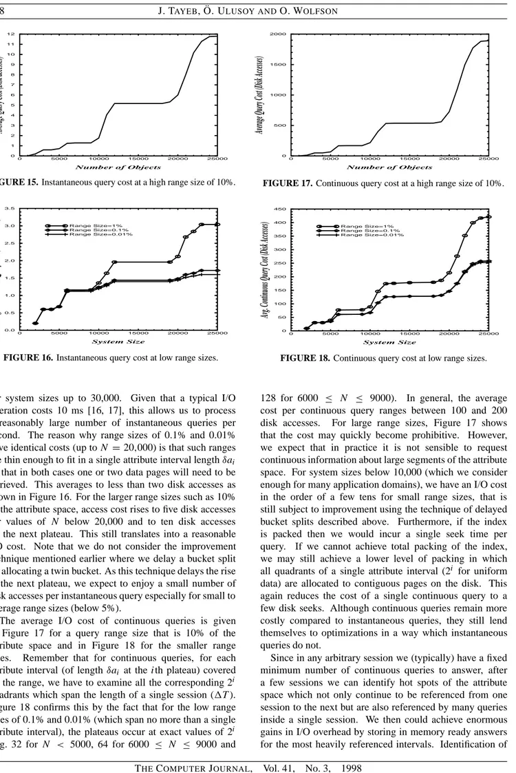
A quadtree-based dynamic attribute indexing method
Tam metin
Şekil

Benzer Belgeler
It is true since one person can not only see his/her face but also look after other several factors including pose, facial expression, head profile, illumination, aging,
Bütün bu olumsuzluklara rağmen 1932 yılından sonra hem Türkiye'de hem Bursa'da ipekböcekçiliği yapan aile sayısı, açılan tohum kutusu ve en önemlisi yaş koza
Hak ve halk âşıklığı yolunda bir Bektaşî ozan olarak, Garip mahlası ile saf ve temiz bir Türkçe içerisinde havalandırdığı türkülerinde hep sevgi, saygı,
Bakırköy Tıp Dergisi, Cilt 9, Sayı 3, 2013 / Medical Journal of Bakırköy, Volume 9, Number 3, 2013 141. kullanımı; lökopeni, trombositopeni, aplastik anemi,
Bu çalışmada ise farklı kaplama mesafelerine sahip mini İHA’ların görev etkinliğini ar- tırmak için, ilk önce değişen hava şartları ve koşulların etkisi
In Section 3.1 the SIR model with delay is constructed, then equilibrium points, basic reproduction number and stability analysis are given for this model.. In Section
number of customers are set to zero and only the total salvage value is listed. Since in the base scenario it is optimal to order 370 items in the dynamic model, the optimal
Our experiments on the ImageCLEF-2009 Medical Annotation database revealed that applying attribute selection on local binary patterns provide comparable classification accuracies
