0885–3010/$25.00 © 2010 IEEE Abstract—Finite element method (FEM) is used for
tran-sient dynamic analysis of capacitive micromachined ultrasonic transducers (CMUT) and is particularly useful when the mem-branes are driven in the nonlinear regime. One major disad-vantage of FEM is the excessive time required for simulation. Harmonic balance (HB) analysis, on the other hand, provides an accurate estimate of the steady-state response of nonlinear circuits very quickly. It is common to use Mason’s equivalent circuit to model the mechanical section of CMUT. However, it is not appropriate to terminate Mason’s mechanical LC sec-tion by a rigid piston’s radiasec-tion impedance, especially for an immersed CMUT. We studied the membrane behavior using a transient FEM analysis and found out that for a wide range of harmonics around the series resonance, the membrane dis-placement can be modeled as a clamped radiator. We con-sidered the root mean square of the velocity distribution on the membrane surface as the circuit variable rather than the average velocity. With this definition, the kinetic energy of the membrane mass is the same as that in the model. We derived the force and current equations for a clamped radiator and implemented them using a commercial HB simulator. We ob-served much better agreement between FEM and the proposed equivalent model, compared with the conventional model.
I. Introduction
c
apacitive micromachined ultrasonic transducers (cMUTs) [1] were widely studied and fabricated in the past decade. cMUTs with some unique capabilities attracted the attention of researchers working with ap-plications such as medical imaging, high-intensity focused ultrasound, intravascular ultrasound, airborne acoustics, microphones, and nondestructive evaluation. Fabrication of cMUTs for those applications requires tedious pro-cess steps, which are time consuming and expensive [2], [3]. Therefore, an accurate and fast simulation method is needed for designing cMUTs.The efforts for simulating the cMUTs have started with the development of an equivalent circuit model [1],
based on Mason’s equivalent circuit [4] for electroacous-tic devices. different models for defining the equivalent circuit elements are available in the literature [1], [5]– [7]. However, finite element method (FEM) simulations are still needed [8] to simulate the cMUT operation, including the nonlinear effects, medium loading, cross talk, and the effect of the higher order harmonics. re-cently, fully analytical models are developed for fast and efficient results of frequency response analysis [9]. FEM simulation packages such as ansys (ansys Inc. can-onsburg, Pa) are powerful tools and extensively used for the analysis of cMUTs. FEM analysis predicts the performance of a particular design accurately, and hence, it is a very good testing and tuning tool. However, the computational expense required for the solution makes FEM tools unsuitable for using them in design stage. For instance, transient dynamic analysis of a cMUT is crucial to understanding the nonlinear behavior of the cMUT. However, it has high computational cost and re-quires many cycles to reach the steady state. It does not rapidly respond when a parameter is altered, and hence, an idea about its effect cannot be instantly grasped by the designer. calculated design charts for a large array of circular cMUTs are available in the literature [10] but lack the nonlinear effects when the cMUTs are driven with a high excitation voltage. In recent years, the efforts to model the nonlinear behavior of cMUTs under large excitations [6], [11] have increased due to the emerging need for applications that require nonlinear excitation [12]–[16].
In this work, we have developed an equivalent circuit, which takes into account the nonuniform velocity distribu-tion across a membrane and predicts the nonlinear behav-ior of a circular cMUT. This model is based only on the physics of the device and does not employ FEM for any parameter determination. The equivalent circuit accurate-ly includes the effect of the immersion medium loading. a linear equivalent circuit model can predict the small signal behavior of cMUT. However, cMUT exhibits strong non-linear behavior even at very low ac excitation. a non-linear mechanical section in the equivalent circuit with a consis-tent radiation impedance is solved by harmonic balance (Hb) analysis. We perform transient and harmonic bal-ance simulations and show that the results are consistent with the FEM results.
Nonlinear Modeling of an Immersed
Transmitting Capacitive Micromachined
Ultrasonic Transducer for Harmonic Balance
Analysis
H. Kagan oguz, selim olcum, Student Member, IEEE, Muhammed n. Şenlik, Student Member, IEEE, Vahdettin Taş, abdullah atalar, Fellow, IEEE, and Hayrettin Köymen, Senior Member, IEEE
Manuscript received april 10, 2009; accepted october 9, 2009. This work is supported in part by the Turkish scientific and research council (TUbITaK) under project grants 105E23 and 107T921. so acknowledg-es the support of TUbITaK and asElsan for their Ph.d. scholarship Programs. aa thanks TUba for the research support.
The authors are with the Electrical and Electronics Engineering department, bilkent University, ankara, Turkey (e-mail: koymen@ ee.bilkent.edu.tr).
We have demonstrated the use of the proposed method by designing the time-waveform of the excitation signal to obtain the given acoustic radiation signal at the output of the cMUT.
II. analytical Equivalent circuit Model It is common to use Mason’s equivalent circuit to model the mechanical section of a cMUT [1], [4]. Mason’s circuit is comprised of a series LC section, where L represents the equivalent mass, which is 1.8 times the membrane mass, and C stands for the inverse of the spring constant of the membrane. In this equivalent circuit, the through and across variables are the average particle velocity and the total force on the driven surface of the membrane, re-spectively. In vacuum, where the medium loading is zero, Mason’s mechanical section accurately models the cMUT and agrees with the FEM simulation results [5].
When the device is immersed, it is necessary to con-sider the terminating radiation impedance in the equiva-lent circuit to represent the device behavior correctly. The radiation impedance of a radiator is determined by the particle velocity distribution across its aperture. It is the ratio of total power radiated from the transducer to the square of the absolute value of a nonzero reference veloc-ity. Therefore, the through and across lumped variables must be defined in such a way that they are consistent both in the equivalent circuit model and in the radiation impedance.
A. Velocity Profile and the Radiation Impedance
The acoustic radiation from radiators with nonuniform velocity profiles is studied by Greenspan [17]. The par-ticle displacement and the velocity profile across circular clamped membranes are not uniform and can be very well approximated by the profiles that Greenspan studied:
v r n v r a r a n ( ) = ( +1) é1- 22 < ë ê ê ù û ú ú avg for , (1)
where a is the radius of the aperture, r is the radial po-sition, vavg is the average velocity along the membrane
surface, and n is a constant that specifies the type of the profile. If n = 0, then (1) stands for the profile of a rigid piston. For a clamped membrane, as the cMUT shown in Fig. 1, n = 2 approximates the nonuniform profile. The radiation impedance of a velocity profile similar to that of a cMUT is given as normalized radiated power of a clamped radiator (n = 2) in [17].
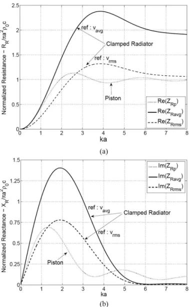
When the cMUT is immersed in water, it is reasonable to assume that the electro-mechanical behavior, hence the model, of the membrane remains intact. However, interac-tion between the membrane and the medium loads the mechanical section. In Fig. 2, the real and imaginary parts of the normalized radiation impedance of the piston radia-tor, Zrp, and the clamped radiator, Zravg, are shown with respect to ka, where k is the wave number. Mason’s circuit and the radiation impedance Zravg are compatible, be-cause the through lumped variable in both is the average Fig. 1. 2-d view of the circular cMUT geometry. Top electrode is placed
at the bottom of the membrane. The dimensional parameters of the cMUT and the cross-section of an infinitesimal ring on the membrane are depicted.
Fig. 2. (a) real (resistive) and (b) imaginary (reactive) parts of the radiation impedance of the piston and the clamped radiator normalized to πa2ρ0c, where ρ0 and c are the density and the velocity of sound in
the immersion medium. For a clamped radiator, both average and rms velocity of the membrane are used as the reference velocity and shown separately.
velocity, vavg. Zravg is considerably different than Zrp of a
piston as depicted in Fig. 2. For example, the real part of
Zravg is 1.8 times that of Zrp for large ka.
The inadequacy of simply terminating Mason’s mechani-cal LC section by a rigid piston’s radiation impedance in water, to model the immersed cMUT, is demonstrated in [18], [19]. This is due to the fact that a rigid piston has a uniform velocity profile (n = 0), whereas cMUT can be bet-ter approximated by n = 2 in (1). The real part (resistive) of
Zrp and Zravg are similar for ka < 1, as depicted in Fig. 2(a),
whereas the reactive parts are not. In Mason’s equivalent circuit, the turns ratio of the electromechanical transformer and the input capacitance are derived with parallel plate as-sumption, but the mechanical impedance is found based on the clamped membrane boundary conditions [4]. consider-ing all these factors, it is not appropriate to combine Mason’s model with the piston radiation impedance.
B. Root Mean Square Velocity
The average velocity is not an appropriate lumped vari-able to determine the kinetic energy of the membrane, which is a distributed system. The kinetic energy calcu-lated using the mass of the membrane and average veloc-ity is less than the actual energy of the membrane. The kinetic energy, EK, of the membrane mass is
E v r v r t r r t a a v r v r r r K m a m = =
ò
ò
12 1 2 1 0 0 2 2 2 ( ) ( ) ( ) ( ) ( ) * * r q r p p q p d d d d 00 0 2 aò
ò
é ë ê ê ê ê ù û ú ú ú ú p , (2)where v(r) is the velocity normal to the surface of the membrane, ρ is the density, tm is the thickness, and ρtmπa2
is the total mass of the membrane. The term in square brackets is the square of rms velocity:
v a v r v r r r a rms = 12 ( ) ( ) d d 0 2 0 * p q p
ò ò
. (3)For a rigid piston (n = 0), both average and rms velocity are equal and the model parameters are the same. The relationship between the average velocity, vavg, the rms
velocity, vrms, and the peak velocity at the center of the
membrane, vp, are
v n
n v vp n v
rms= 1 avg and avg
2 1 = ( 1)
+
+ + . (4)
For n = 2, |vrms|2 = 1.8|v
avg|2 and by using (2)–(4),
EK =1
(
tm a)
vrms 2 2 2 r p (5) =1(
)
2 1 8 2 2 r ptm a . vavg . (6)Hence, the kinetic energy of the membrane mass in (2) is preserved only if rms velocity, vrms, is employed as the
through variable. otherwise, L, representing the mass in the model, must be 1.8 times the membrane mass when
vavg is employed.
C. RMS Equivalent Circuit Model Parameters
To derive an equivalent circuit with the rms velocity as the through variable, we consider the mechanical imped-ance of a clamped membrane in vacuum. We begin by defining the mechanical impedance as the ratio of total power across the driven surface of the membrane and the square of vrms, Z Pw v p r v r r r v a rms Total rms rms d = 2 = 2 ( ) ( ) * 2 0
ò
p , (7)where p(r) is the normal force per unit area distribution on the driven surface. assuming that p(r) is constant across the membrane surface and n = 2 for clamped mem-brane, this impedance expression becomes |vavg|2/|vrms|2
times the Mason’s mechanical impedance obtained from the total force to average velocity ratio. Zrms can readily
be calculated by FEM analysis. Matching the slope of the impedance of an equivalent series LC section to (7) at the resonance frequency reveals that Lrms is exactly equal to
the mass of the membrane, rather than 1.8 times the mass as in Mason’s circuit.
Lrms =r ptm a2 (8) Hence, the lumped inductance in the rms circuit mod-els the effect of mass directly. To preserve the resonance frequency in vacuum, the capacitance in Mason’s circuit representing the compliance of the membrane must be multiplied with |vrms|2/|vavg|2 = 1.8,
C a Y tm rms = 1.8 1 16 2 2 0 3 ( ) , - s p (9)
where Y0 is the young’s modulus, σ is the Poisson’s ratio
of the membrane material, and tm is the membrane
thick-ness. a correction to this formula may be necessary for membranes with tm/a > 0.1 as explained in [5].
If vrms is employed in the “normalized power”
expres-sion instead of vavg, we obtain the normalized radiation
impedance Zrrms, depicted in Fig. 2, which is |vavg|2/|vrms|2
times the “normalized power” in [17]. calculation of Zrrms
can be found in the appendix.
III. Fundamental Equations of the cMUT static and harmonic analyses in FEM can predict the dc deflection and the fundamental velocity profile,
respec-tively. We studied the membrane behavior using dynamic transient FEM analysis and at 80 discrete radial positions along the membrane surface, we fitted a sum of sinusoids, which consists of the fundamental and its first 5 harmon-ics, to each of the time-domain velocity data obtained at these 80 locations along the radius. Then, the amplitude distribution of each harmonic along the radius is used to find the velocity profile at that frequency. The phase of each harmonic is observed to be almost constant across the radius. We fitted (1) to the obtained velocity profile of each harmonic component and we observed that n in (1) is dependent on the bias voltage and varies between 1.95 and 2.2. as the bias voltage increases, n also increases. nevertheless, the membrane velocity profile can be mod-eled quite accurately as a clamped radiator (n = 2), up to more than 2 times the series resonance frequency.
It is possible to derive a nonlinear analytical electrome-chanical model for the cMUT. When the cMUT is driven by a voltage V(t) = Vdc + Vac(t), the electrostatic force acting on the small ring of area 2πrδr can be calculated by taking the derivative of the stored energy in the clamped capacitance dF r t V t dC x r t x ( , ) = 1 2 ( ) ( ( , )) 2 d d
[
]
, (10)where x(r,t) is the membrane displacement normal to the surface and the capacitance of the ring is
dC x r t e p dr r tg x r t ( ( , )) = 2 ( , ) 0 - . (11)
Total force on the driven surface of the membrane is found by integrating (10) as δr → 0 F t V t r r t x t r a a g p n tot d / ( ) = ( ) ( ) 1 0 2 0 2 2 2 e p
ò
--[
( )]
, (12)where tg is the gap height, ε0 is the free space permittivity, and xp(t) = x(0,t) is the peak displacement at the center of the membrane. Eq. (12) can be evaluated for n = 2 as follows F t C V t t t t x t g g g p x t t x t t p g p g tot 1 tanh ( ) = ( ) 4 ( ) 0 2 ( ) ( ) - +
(
)
é ë ê ê ê ê ù -ûû ú ú ú ú , (13)where C0 = ε0πa2/tg. note that when xp(t) < 0,
tanh / / tan / / 1 1 -
(
)
-(
-)
-x t t x t t x t t x t t p g p g p g p g ( ) ( ) = ( ) ( ) , (14)which is a more useful expression for a simulator.
For small displacements around the point xp(t) = 0, Taylor series expansion of (13) provides a simpler math-ematical interpretation, where the leading terms are
F t C V t t x t t x t t g p g p g tot( ) 02 ( ) 1 23 ( ) 35 ( ) 2 2 » + + æ è çç ç ö ø ÷÷÷÷ é ë ê êê ù û úú úú. (15)
The current flowing through the electrodes of the small ring is the time derivative of the charge on this ring
d d d d d d [ ] [ ] . d d d Q r t t C x r t V t t C x r t t V t ( , ) = ( ( , )) ( )+ ( ( , )) ( ) (16)
The first term in (16) is the capacitive current and the sec-ond one is induced by the membrane motion and, there-fore, we call it the velocity current. We note that both current components depend on the instantaneous value of the membrane displacement. considering an equivalent circuit, capacitive current flows through the shunt capaci-tance at the electrical side and velocity current is the one that gives rise to velocity at the mechanical port. To find the total capacitive current, icap, we evaluate the integral as δr → 0 i t V t t r r t x r t C V t t x t t g a p g cap 1 d d d d d tanh / ( ) ( ) ( , ) ( ) ( ) = -=
ò
-2 0 0 0 pe (( ) x t tp( ) g . / (17)as shown in Fig. 3, this is the sum of currents in C0 and a
nonlinear component ic. Hence, the nonlinear part is
i t C V t t x t t x t t c p g p g ( ) = ( ) ( ) ( ) 1 0 d d tanh / / 1 - ( ) -é ë ê ê ù û ú ú . (18)
Taylor series expansion of ic gives
i t C V t t x t t x t t c p g p g ( ) ( ) 1 3 ( ) 1 5 ( ) 0 2 » æ è çç ç ö ø ÷÷÷÷ + æèççç ö ø ÷÷÷÷ é d d ëë ê êê ù û ú úú. (19)
To find the velocity current flowing through the clamped capacitance, the second term at the right hand side of (16) is rearranged and integrated over the membrane surface as δr → 0 i t V t x t t r a r r t x t r a p a g p vel d d / d / ( ) = 2 ( ) ( ) 1 ( ) 1 0 0 2 2 2 2 2 2 pe
ò
-- -( ) ( )[[
]
2, (20) Fig. 3. nonlinear large signal equivalent circuit. ic, ivel, and Ftot are givenby (18), (21), and (13) with x tp( ) = 5CrmsF tc( ). Lrms and Crms are found
which is i t C V t x t x t t t t x t p p g g p x t t x t t p g p vel 1 d d tanh ( ) = ( ) 2 ( ) ( ) ( ) 0 ( ) ( ) - -gg é ë ê ê ê ê ù û ú ú ú ú . (21)
Taylor series expansion of the velocity current expression is i t C V t t x t t x t t x t t g p p g p g vel d d ( ) ( ) ( ) 1 3 2 5 ( ) 3 7 ( ) 0 2 » + + æ è çç ç ö ø ÷÷÷÷ éé ë ê êê ù û ú úú. (22)
It is possible to obtain the small signal model parame-ters of the equivalent circuit from the Taylor series expan-sions of Ftot, ic, and ivel. assuming that the membrane
dis-placement is very small compared with tg around xp = 0,
we write from (15) F t V t C t x t t g p g tot( ) ( ) 2 1 2 ( ) 3 2 0 » é + ë ê ê ù û ú ú. (23) If we choose Vdc≫ Vac, then V t2( )»VDC2 +2V V tDC ac( ),
and because xavg(t) = xp(t)/3, we find
F t V C t V C t V t V C t x t g g g tot( ) DC DC ac DC avg 2 ( ) ( ) 2 0 0 2 0 2 » + + , (24)
where the first term at the right side represents the static force and the second term is the ac force due to electro-mechanical transformer ratio. The turns ratio of the trans-former can be found from the second term as N = VdcC0/
tg which is the same as that found in [1]. The third term in (24) is the amount of spring softening, due to increased electrostatic force caused by the displacement. It is like a negative capacitor of value −C0/N2, which is also
consis-tent with [1].
For very small displacements around xp = 0, the nonlin-ear part, ic, is negligible, and the velocity current is
i t C V t x t t C V t v t g p g vel DC DC rms d d ( ) 3 ( ) = 5 3 ( ) 0 0 » . (25)
The small signal parameters are sufficient to model a cMUT, as long as the membrane displacement is very small around xp = 0 and the spring softening is not very
pronounced. However, cMUTs are always used with dc bias, and the assumption of operation around xp = 0 is
not realistic even under small signal ac conditions. also, it is apparent, even from the linearized equations, that the existence of large displacements can significantly alter the device behavior. To investigate the nonlinear nature of the cMUT, the unknown membrane displacement must be determined, so that the force and current equations can be implemented accordingly.
IV. Modeling of cMUT for Harmonic balance analysis
The harmonic balance (Hb) analysis is a frequency do-main nonlinear circuit analysis method, which is capable of finding the large signal, steady-state response of non-linear circuits and systems. non-linear circuits are modeled in frequency domain, while the nonlinear components are modeled with their time domain characteristics [20]. In this method, the input to the system is assumed to be a sinusoid, and the steady-state solution is found as the sum of a fundamental component and its harmonics. The method is significantly more efficient than time-domain simulators when the circuit contains components that are modeled in the frequency domain and the time constants are large compared with the period of the fundamental excitation frequency. In [21], a harmonic balance approach is applied to the weakly nonlinear equations of a MEMs microphone to characterize the unknown system param-eters.
as seen in Fig. 3, we used a linear mechanical sec-tion and a consistent radiasec-tion impedance. a commercial harmonic balance simulator (advanced design system, agilent Technologies, Palo alto, ca) is used to imple-ment the physical equations derived in section III. We also performed transient simulations in addition to har-monic balance simulations and compared the results with FEM simulations.
The mechanical section is constructed as lumped ele-ments and a component that encapsulates the radiation impedance, Zrms(ω), in the frequency domain with a
suit-able (Touchstone formatted) file. a symbolically defined device in the Hb simulator enables us to create, multiport nonlinear equation-based components. We implemented the physical equations of the cMUT by relating port cur-rents, port voltages, and their derivatives in this device. Eq. (13) is used to generate the total force, Ftot, at the
mechanical side of the equivalent circuit. Eqs. (18) and (21) give ic and ivel in the model of Fig. 3; xp(t) in those
equations represents the instantaneous charge in Crms,
and it can be found from x tp( ) = 5CrmsF tc( ). When the
absolute peak membrane displacement is 0.1% of the gap height or less, Taylor expansions of the equations are used to avoid convergence problems in the simulator that might occur when xp becomes very small. We can calculate total
power, total force, and capacitive and velocity currents as outputs from the device.
A. Static Analysis
We compared the dc performance of the Hb model with the FEM static analysis results. a cMUT membrane immersed in water with the top electrode placed at the bottom of the membrane is considered in all FEM simula-tions. static deflection of a cMUT cell is examined with respect to dc bias voltage, the physical dimensions and the material properties of which are given in Table I. The cMUT collapses at 95 V in FEM analysis and at 97 V
in Hb analysis, where tm/a = 0.05. In addition, increas-ing the thickness of the membrane, tm, and repeating the analysis up to tm/a = 0.2 revealed that the amount of error is confined within 3%. It must be noted that the choice of Mason’s or rms mechanical section does not have any effect on the dc performance, and the membrane displacement is determined by the force model employed. It is noticed that the equivalent circuit predicts a higher peak displacement compared with FEM analysis.
The procedure is notably simplified while deriving the mechanical impedance of the cMUT with the assumption of constant force distribution in (7). The across variable is simply defined as total force on the membrane, Ftot, consistent with the phasor notation. However, there is an effect of nonuniform force distribution that becomes sig-nificant, particularly when the membrane is biased close to the collapse point. FEM analysis reveals that the force distribution is effectively uniform under low bias condi-tions, and a nonuniform component emerges as the bias is increased and becomes significant at high bias levels.
B. Frequency Response Analysis
1) Small-Signal Analysis: a prestressed harmonic
anal-ysis in FEM calculates the dynamic response of a biased membrane, assuming that the harmonically varying stress-es are much smaller than the prstress-estrstress-ess itself. It dostress-es not take into account any kind of nonlinearity. Therefore, it is meaningful to evaluate only the small signal frequency response, where the membrane should not be biased very near to the collapse point. We can define the transducer’s electrical admittance as Yin = Gin + jBin, where Gin is the conductance and Bin is the susceptance of the cMUT. To follow the progress made in the proposed model, first, Ma-son’s small signal equivalent circuit is analyzed. This cir-cuit is composed of an electromechanical transformer with turns ratio, N = VdcC0/tg, which separates the spring softening capacitance, −C0/N2, and the mechanical LC
section defined in [4] from the shunt input capacitance,
C0. In Fig. 4(a), the small signal electrical conductance of an immersed cMUT cell is found by terminating this cir-cuit with the radiation impedance of a piston, Zrp. at bias voltages, 60 V, 70 V, and 80 V, a 1-V peak ac signal is applied, and the results are compared with the FEM har-monic analysis results. at Vdc = 90 V, the membrane
col-lapses around the resonance frequency. It can be seen that the resonance frequencies are much lower and the spring softening is more pronounced in the FEM predictions.
Improvement is obtained when Mason’s equivalent me-chanical section and the corresponding radiation imped-ance is replaced by the rms equivalent mechanical section,
Lrms and Crms, and the radiation impedance Zrrms, re-spectively, as explained in section II-c. This is the circuit shown in Fig. 3, where root mean square velocity, vrms, and Ftot are the through and across variables, respectively. The conductance obtained by this model for same bias lev-els is depicted in Fig. 4(b), together with the FEM results. Much better agreement is achieved in terms of peak con-ductance level, resonance frequency estimation, and the spring softening effect. However, in Hb results, the ampli-tude of the conductance and the resonance frequency are slightly higher compared with FEM. For higher Vac/Vdc, resonance frequency predictions of both analyses converge to each other. We have also observed similar results for cMUTs having the same radii but thicker membranes up to tm/a = 0.2. We can see that resonance frequency shift due to increased bias voltage falls short as the bias volt-age increases, where the nonuniform force distribution be-gins to be significant and the clamped membrane velocity profile changes (n increases). These 2 major variations TablE I. cMUT dimensions and constant Parameters Used in
the simulations.
Parameter Value
radius, a 20 μm
Gap height, tg 0.25 μm
Thickness of membrane, tm 1 μm collapse voltage, Vcol 95 V Poisson’s ratio of si3n4, σ 0.263 density of membrane (si3n4), ρ 3.27 g/cm3
young’s modulus of si3n4, Y0 3.2 × 10⁵ MPa
density of water, ρ0 1 g/cm3
speed of sound in water, c 1500 m/sec
Fig. 4. small signal electrical conductance of a cMUT cell in water; 1-V peak ac signal is applied at bias voltages of 60 V, 70 V, and 80 V. Finite element method (FEM; solid) results are acquired from prestressed har-monic analysis and compared with (a) the frequency response of Mason’s small signal equivalent circuit, which is terminated by the radiation im-pedance Zrp and (b) the harmonic balance (Hb) analysis of the proposed equivalent circuit shown in Fig. 3.
increase the error rate as we approach close to the col-lapse point.
We have also carried out the transient FEM analysis at several discrete frequencies to validate the linear behavior of the membrane under these drive conditions. We ob-served that the transient analysis yields exactly the same results with the prestressed harmonic analysis in FEM for linear operations.
2) Nonlinear Analysis: Prestressed harmonic analysis is
reliable for small signal simulations. To find out the large signal performance of the introduced model, we employed dynamic transient analysis in FEM. on account of this, it is necessary to apply large Vac as long as the membrane
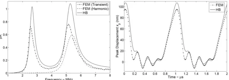
does not collapse during the transient process. In Fig. 5, the real part of the fundamental component of the source current is shown for Hb analysis, together with transient and prestressed harmonic FEM analyses. In these simu-lations Vdc and Vac are 10 V and 40 V peak,
respec-tively. There is a peak at half the resonance frequency, because the second harmonic coincides with the resonance frequency causing significant membrane velocity at the resonance. However, prestressed FEM harmonic analysis cannot predict the nonlinear behavior. on the other hand, the rms equivalent circuit predicts the conduction peak at half the resonance frequency quite well. The data of the equivalent circuit for this figure is obtained in less than one minute, while producing the data of transient FEM analysis took approximately one day on the same computer.
C. Transient Analysis
In Fig. 6, the displacement at the center of the mem-brane is plotted, which is driven with a sinusoidal signal
of 50-V peak amplitude at 1 MHz, superimposed on 40-V bias voltage. The drive frequency is approximately one-fifth the resonance frequency of the cMUT cell. The Hb solution converges within 1 second, which approximates the steady state of a transient FEM solution accurately. nonlinear effects are very pronounced, because a large ac signal is employed.
although the harmonic balance simulates the nonlin-ear circuits rapidly, it only produces the steady-state re-sponse. We also studied the transient effects of the same rms equivalent circuit by means of transient simulations. Fig. 7 shows the peak displacement of the membrane, where the membrane is biased to 40 V and a rectangular pulse of 40-V amplitude is superimposed for 0.1 μs dura-tion. although the agreement is impressive, FEM simula-tion predicts a slightly faster damping.
D. Pulse Shaping
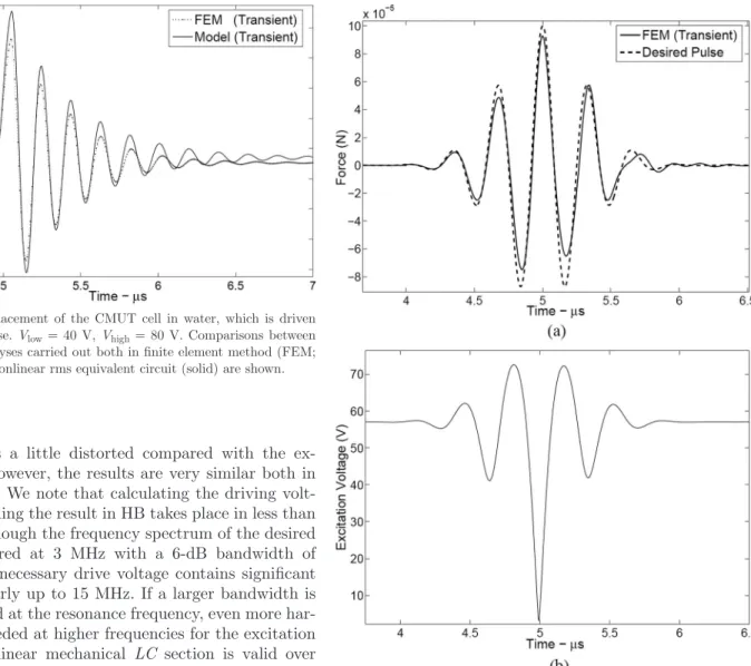
Using the equivalent model equations and parameters, we can design the shape of the driving voltage to obtain the desired acoustic signal. a pressure pulse, which has a Gaussian-shaped frequency spectrum, is an appropriate choice at the surface of the membrane. First, the mag-nitude, the bandwidth, and the center of this spectrum are determined. Then, the rms velocity is found in the frequency domain, from the ratio of the desired total force at the top surface of the membrane and the impedance of the medium. The total force, Ftot, at the driven surface is
calculated from the product of rms velocity and the total mechanical impedance. Finally, the driving voltage is cal-culated from (13).
If the desired pulse across the radiation impedance is as shown in Fig. 8(a), the model predicts the driving voltage as given in Fig. 8(b). To check the validity of this driving voltage, it is applied in FEM transient analysis, and the obtained result is also plotted in Fig. 8(a). The obtained Fig. 5. real part of the fundamental electrical source current of the
cMUT cell in water for Vdc = 10 V and a peak ac voltage of 40 V.
large signal response is examined in finite element method (FEM), both with transient (dotted) and prestressed harmonic analysis (dashed). root mean square equivalent circuit result is obtained from harmonic balance (Hb; solid) simulation.
Fig. 6. Peak displacement of the cMUT cell in water, which is driven with a high sinusoidal voltage at a frequency one-fifth the resonance. comparisons between transient analysis in finite element method (FEM; dotted) and harmonic balance (Hb; solid) simulation of the nonlinear rms equivalent circuit are shown.
pulse shape is a little distorted compared with the ex-pected one. However, the results are very similar both in FEM and Hb. We note that calculating the driving volt-age and obtaining the result in Hb takes place in less than 1 minute. although the frequency spectrum of the desired pulse is centered at 3 MHz with a 6-db bandwidth of 1.2 MHz, the necessary drive voltage contains significant harmonics nearly up to 15 MHz. If a larger bandwidth is aimed centered at the resonance frequency, even more har-monics are needed at higher frequencies for the excitation voltage. The linear mechanical LC section is valid over a wide frequency band around the resonance frequency, but it fails to represent the membrane dynamics as the frequency approaches to antiresonance. The antiresonance of this particular immersed membrane is around 25 MHz. as long as the frequency spectrum of the obtained driv-ing voltage is confined in the valid operation band of the model, the obtained pulse shape will be very similar to the desired one.
V. conclusions
an alternative equivalent circuit for immersed circular cMUT is presented for linear and nonlinear operations. root mean square velocity is used instead of the com-monly used average velocity. a clamped profile is used when deriving the analytical force and current equations, and the corresponding radiation impedance is employed. all parameters in the model can be simply calculated ana-lytically for particular device dimensions, independent of FEM analysis. although there is no parameter tuning in our model using the FEM results, the predictions are ac-curate.
differences between FEM results and the model pre-dictions can be accounted for the approximations in the
model equations. one of them is the variable nature of n as a function of bias voltage. FEM analysis predicts that the clamped membrane deflection profile can be modeled by (1) for n varying between 1.95 and 2.2. We have taken
n = 2. Furthermore, the force distribution across the
mem-brane is not uniform. FEM simulations show that force is larger at the center of the membrane compared with its periphery. We used the total force on the membrane as the lumped across variable in the model, which estimates a lower deflection at the center.
appendix radiation Impedance
radiation impedance of a transducer with a certain ve-locity profile is the ratio of total power radiated from the Fig. 7. Peak displacement of the cMUT cell in water, which is driven
with a 0.1 μs pulse. Vlow = 40 V, Vhigh = 80 V. comparisons between
the transient analyses carried out both in finite element method (FEM; dotted) and the nonlinear rms equivalent circuit (solid) are shown.
Fig. 8. (a) The desired pulse shape (dashed) and the achieved total force (solid) at the top surface of the cMUT in water, which is obtained when the designed voltage waveform in (b) is applied.
acoustical terminals to the square of the absolute value of a nonzero reference velocity:
Z P r v r r r V V P V R i i i a =2 0 ( ) ( ) = * * 2 p
ò
d TOTAL . (26)When rms velocity is chosen for Vi, the radiation imped-ance derived in [17] becomes
Z a c ka F ka jF ka Rrms= 1 20 ( ) (2 ) (2 ) 2 0 9 1 2 p r æ -
[
+]
è çç ç ö ø ÷÷÷÷, (27) where ρ0 is the density and c is the speed of sound of the immersion medium andF y y y J y y y J y y y 1 4 2 1 2 0 5 7 ( ) = ( 91 504) ( ) 14 ( 18) ( ) 16 768 - + + -- / - / , (28) and F y y y H y y y H y y y 2 4 2 1 2 0 4 2 ( ) = ( 91 504) ( ) 14 ( 18) ( ) 14 15 168 - - + - -+ / p- /pp. (29)
Jn and Hn are the nth order bessel and struve functions,
respectively.
For ka < 0.1, Zrrms = Rrrms + jXrrms can be
approxi-mated as ZRrms » a c ka +j ka é ë ê ê ù û ú ú 5 9 ( ) 2 2 17325 ( ) 2 0 2 16 p r p . (30) references
[1] I. ladabaum, X. Jin, H. soh, a. atalar, and b. Khuri-yakub, “sur-face micromachined capacitive ultrasonic transducers,” IEEE Trans.
Ultrason. Ferroelectr. Freq. Control, vol. 45, no. 3, pp. 678–690, May
1998.
[2] J. Knight, J. Mclean, and F. degertekin, “low temperature fab-rication of immersion capacitive micromachined ultrasonic trans-ducers on silicon and dielectric substrates,” IEEE Trans.
Ul-trason. Ferroelectr. Freq. Control, vol. 51, no. 10, pp. 1324–1333,
oct. 2004.
[3] y. Huang, a. Ergun, E. Haeggstrom, M. badi, and b. Khuri-yakub, “Fabricating capacitive micromachined ultrasonic transducers with wafer-bonding technology,” J. Microelectromech. Syst., vol. 12, no. 2, pp. 128–137, apr. 2003.
[4] W. Mason, Electromechanical Transducers and Wave Filters, 2nd ed. new york: Van nostrand, 1948.
[5] H. Koymen, M. senlik, a. atalar, and s. olcum, “Parametric linear modeling of circular cMUT membranes in vacuum,” IEEE Trans.
Ultrason. Ferroelectr. Freq. Control, vol. 54, no. 6, pp. 1229–1239,
Jun. 2007.
[6] a. lohfink and P.-c. Eccardt, “linear and nonlinear equivalent cir-cuit modeling of cMUTs,” IEEE Trans. Ultrason. Ferroelectr. Freq.
Control, vol. 52, no. 12, pp. 2163–2172, dec. 2005.
[7] d. certon, F. Teston, and F. Patat, “a finite difference model for cMUT devices,” IEEE Trans. Ultrason. Ferroelectr. Freq. Control, vol. 52, no. 12, pp. 2199–2210, dec. 2005.
[8] G. yaralioglu, s. Ergun, and b. Khuri-yakub, “Finite-element analysis of capacitive micromachined ultrasonic transducers,” IEEE
Trans. Ultrason. Ferroelectr. Freq. Control, vol. 52, no. 12, pp. 2185–
2198, dec. 2005.
[9] I. o. Wygant, M. Kupnik, and b. T. Khuri-yakub, “analytically calculating membrane displacement and the equivalent circuit mod-el of a circular cMUT cmod-ell,” in Proc. IEEE Ultrasonics Symp., nov. 2008, pp. 2111–2114.
[10] s. olcum, M. senlik, and a. atalar, “optimization of the gain-bandwidth product of capacitive micromachined ultrasonic trans-ducers,” IEEE Trans. Ultrason. Ferroelectr. Freq. Control, vol. 52, no. 12, pp. 2211–2219, dec. 2005.
[11] M. Kupnik, I. o. Wygant, and b. T. Khuri-yakub, “Finite element analysis of stress stiffening effects in cMUTs,” in Proc. IEEE
Ultra-son. Symp., nov. 2008, pp. 487–490.
[12] s. Wong, r. Watkins, M. Kupnik, K. Pauly, and b. Khuri-yakub, “Feasibility of Mr-temperature mapping of ultrasonic heating from a cMUT,” IEEE Trans. Ultrason. Ferroelectr. Freq. Control, vol. 55, no. 4, pp. 811–818, apr. 2008.
[13] b. bayram, G. yaralioglu, M. Kupnik, a. Ergun, o. oralkan, a. nikoozadeh, and b. Khuri-yakub, “dynamic analysis of ca-pacitive micromachined ultrasonic transducers,” IEEE Trans.
Ul-trason. Ferroelectr. Freq. Control, vol. 52, no. 12, pp. 2270–2275,
dec. 2005.
[14] J. chen, X. cheng, c.-c. chen, P.-c. li, J.-H. liu, and y.-T. cheng, “a capacitive micromachined ultrasonic transducer array for minimally invasive medical diagnosis,” J. Microelectromech. Syst., vol. 17, no. 3, pp. 599–610, Jun. 2008.
[15] I. Wygant, M. Kupnik, J. Windsor, W. Wright, M. Wochner, G. yaralioglu, M. Hamilton, and b. Khuri-yakub, “50 khz ca-pacitive micromachined ultrasonic transducers for generation of highly directional sound with parametric arrays,” IEEE Trans.
Ultrason. Ferroelectr. Freq. Control, vol. 56, no. 1, pp. 193–203,
Jan. 2009.
[16] I. o. Wygant, M. Kupnik, b. T. Khuri-yakub, M. s. Wochner, W. M. Wright, and M. F. Hamilton, “The design and characterization of capacitive micromachined ultrasonic transducers (cMUTs) for generating high-intensity ultrasound for transmission of directional audio,” in Proc. IEEE Ultrasonics Symp., nov. 2008, pp. 2100– 2102.
[17] M. Greenspan, “Piston radiator: some extensions of the theory,” J.
Acoust. Soc. Am., vol. 65, no. 3, art. no. 608621, Mar. 1979.
[18] G. yaralioglu, M. badi, a. Ergun, and b. Khuri-yakub, “Improved equivalent circuit and finite element method modeling of capacitive micromachined ultrasonic transducers,” in Proc. IEEE Ultrasonics
Symp., vol. 1, oct. 2003, pp. 469–472.
[19] a. bozkurt and M. Karaman, “a lumped circuit model for the ra-diation impedance of a 2d cMUT array element,” in Proc. IEEE
Ultrasonics Symp., vol. 4, sep. 2005, pp. 1929–1932.
[20] s. a. Maas, Nonlinear Microwave and RF Circuits, 2nd ed. nor-wood, Ma: artech House, 2003.
[21] J. liu, d. Martin, T. nishida, l. cattafesta, M. sheplak, and b. Mann, “Harmonic balance nonlinear identification of a capacitive dualbackplate MEMs microphone,” J. Microelectromech. Syst., vol. 17, no. 3, pp. 698–708, Jun. 2008.
H. Kagan Oguz was born in ankara, Turkey, in
1985. He received his b.s. and M.s. degrees in electrical engineering in 2006 and 2009, respec-tively, both from bilkent University, ankara, Tur-key, where he was a research assistant.
He is currently working toward his Ph.d. de-gree in the same department and continues with Meteksan defence Industry Inc. as a research en-gineer in underwater acoustic systems division.
Selim Olcum was born in chicago, Il, in 1981.
He received his b.s. and M.s. degrees in electrical engineering in 2003 and 2005, respectively, both from bilkent University, ankara, Turkey.
He worked as a guest researcher at national Institute of standards and Technology, semicon-ductor Electronics division during the summers of 2002 and 2003. He was a visiting scholar in the Micromachined sensors and Transducers labora-tory of Georgia Institute of Technology, atlanta, Ga, in 2006. He is currently working toward his Ph.d. degree in electrical and electronics engineering at bilkent Univer-sity where he has been a research and teaching assistant since 2003.
His current research interests include optical and acoustical micro-machined sensors and actuators. Mr. olcum is a recipient of the asEl-san Ph.d. scholarship. He has been a member of IEEE and the UFFc society since 2003.
Muhammed N. Senlik was born in Isparta,
Turkey, in 1981. He received his b.s. degree from bilkent University, ankara, Turkey, in 2002 in electrical engineering. He is currently working to-ward his Ph.d. degree in the same department, where he has been a research assistant since 2002.
Vahdettin Tas received a b.s. degree from
Mid-dle East Technical University, ankara, Turkey, in 2007 and an M.s. degree from bilkent University, ankara, Turkey, in 2009, both in electrical engi-neering.
He is currently working toward his Ph.d. de-gree in the department of Electrical Engineering and computer science at the University of cali-fornia, berkeley, ca. His current research inter-ests include micromechanical signal processors and atomic force microscopy.
Abdullah Atalar received his b.s. degree from
Middle East Technical University, ankara, Tur-key, in 1974, and his M.s. and Ph.d. degrees from stanford University, stanford, ca, in 1976 and 1978, respectively, all in electrical engineering. From 1978 to 1980, he was first a postdoctoral fellow and later an engineering research associate at stanford University. For 8 months he was with Hewlett Packard labs, Palo alto, ca. From 1980 to 1986, he was on the faculty of the Middle East Technical University as an assistant professor. In 1986, he joined bilkent University, ankara, Turkey, as chairman of the Electrical and Electronics Engineering department and served in the founding of the department, where he is currently a professor. He is pres-ently the Provost of bilkent University. during 1996–1998 he was a visit-ing professor at stanford University. His current research interests in-clude microwave electronics and micromachined sensors. He was awarded the science award of the Turkish scientific research council (TUbI-TaK) in 1994. He is a Fellow of IEEE and a member of Turkish academy of sciences.
Hayrettin Köymen (M’87–sM’91) received the
b.sc. and M.sc. degrees from Middle East Techni-cal University (METU), ankara, Turkey, in 1973 and 1976, respectively, and the Ph.d. degree from birmingham University, birmingham, UK, in 1979, all in electrical engineering.
He worked as a faculty member in the Ma-rine sciences department (Mersin) and Electri-cal Engineering department (ankara) of METU from 1979 to 1990. He has been a professor at bilkent University, ankara, Turkey, since 1990. His research activities have included underwater acoustic and ultrasonic transducer design, acoustic microscopy, ultrasonic ndT, biomedical in-strumentation, mobile communications, and spectrum management.