High-Throughput, High-Resolution
Interferometric Light Microscopy of Biological
Nanoparticles
Celalettin Yurdakul, Oguzhan Avci, Alex Matlock, Alexander J. Devaux, Maritza V. Quintero,
Ekmel Ozbay, Robert A. Davey, John H. Connor, W. Clem Karl, Lei Tian, and M. Selim Ünlü
*
Cite This:ACS Nano 2020, 14, 2002−2013 Read Online
ACCESS
Metrics & More Article Recommendations*
sı Supporting Information ABSTRACT: Label-free, visible light microscopy is anindispen-sable tool for studying biological nanoparticles (BNPs). However, conventional imaging techniques have two major challenges: (i) weak contrast due to low-refractive-index difference with the surrounding medium and exceptionally small size and (ii) limited spatial resolution. Advances in interferometric microscopy have overcome the weak contrast limitation and enabled direct detection of BNPs, yet lateral resolution remains as a challenge in studying BNP morphology. Here, we introduce a wide-field interferometric microscopy technique augmented by computa-tional imaging to demonstrate a 2-fold lateral resolution improve-ment over a large field-of-view (>100 × 100 μm2), enabling simultaneous imaging of more than 104 BNPs at a resolution of
∼150 nm without any labels or sample preparation. We present a rigorous vectorial-optics-based forward model establishing the relationship between the intensity images captured under partially coherent asymmetric illumination and the complex permittivity distribution of nanoparticles. We demonstrate high-throughput morphological visualization of a diverse population of Ebola virus-like particles and a structurally distinct Ebola vaccine candidate. Our approach offers a low-cost and robust label-free imaging platform for high-throughput and high-resolution characterization of a broad size range of BNPs. KEYWORDS: interference microscopy, nanoparticle detection, biosensing, computational imaging, label-free, Fourier optics
O
ptical detection and morphological characterization of biological nanoparticles (BNPs) including viruses and exosomes in the visible spectrum has been an invaluable tool for life science and engineering.1Shape and size characteristics of these BNPs have strong implications on their circulation,2 biodistribution,3 cell entry pathways,4 and clearance in vivo.5 For example, viruses and mycoplasmas exist in various geometries, that is, rods and spheres, with sizes ranging from tens to hundreds of nanometers. While nonspherical rod and disk-shaped particles can tumble and flow close to blood vessel walls, spherical particles tend to follow laminar flow along the center.6 Virus shape can also increase transmission,7,8 allow escape from small molecule antivirals,9 and aid in evading host responses.10 Accurate characterization of BNP morphology with optical microscopy techniques would provide valuable insights regarding these factors, if two formidable challenges in conventional bright-field microscopy can be overcome: (i) weakly scattering characteristics of BNPs due to exceptionally small size and low-refractive-index difference with surrounding medium limitingthe optical contrast and (ii) subwavelength spatial resolution limit imposed by the imaging system.
Fluorescent labeling is the most prevalent method to alleviate the weak contrast in biological studies. Furthermore, the nonlinearity of fluorescence and stochastic approaches have been utilized to improve the resolution beyond the diffraction limit and led to advancements in super-resolution far-field optical microscopy modalities11−14 for studying biological specimens in previously inaccessible detail. However, fluorescence labeling has practical difficulties and could interfere with sample functionality. Moreover, fluorescence imaging is severely limited by photophysical properties of fluorescent molecules such as phototoxicity and photo-Received: October 28, 2019
Accepted: January 31, 2020
Published: January 31, 2020
Article
www.acsnano.org
Downloaded via BILKENT UNIV on February 12, 2021 at 11:35:04 (UTC).
bleaching. Overcoming these limitations and enabling label-free (direct) imaging of BNPs at high-resolution in their natural environment and without any modifications would have a significant impact in the life sciences. Recent advances in optical microscopy enable highly sensitive direct imaging of BNPs by various contrast enhancement methods.15−21 Wide-field interferometric imaging techniques enhance the weak scattering signal by interfering the signal with a strong referencefield and have demonstrated the label-free detection of very small BNPs such as exosomes,19 viruses,22,23 and synthetic nanoparticles.21,24−26 Furthermore, Ünlü’s group previously demonstrated the detection of viruses in complex media including cell media solution27 and serum.28 Recent advancements in interferometric microscopy techniques improved system sensitivity with pupil engineering and led to single protein detection in sparse samples, yet they do not address the inadequate lateral resolution.20,21,24
Here, we present a computational imaging approach that extends single-particle interferometric reflectance (SPIR) microscopy’s capability from direct detection to detailed morphological characterization of subdiffraction-limited par-ticles. Recently, several computational coherent imaging techniques have demonstrated great advancements in improv-ing spatial resolution.29−35 In particular, our work draws inspirations from Fourier ptychographic microscopy (FPM)32,33and differential phase contrast (DPC).35 In both FPM and DPC, the sample is illuminated from multiple incidence angles to encode the high-frequency information about the sample into the finite passband of the imaging system. Next, a phase retrieval algorithm is applied to
quantitatively recover the object with improved spatial resolution from the captured low-resolution intensity images. In FPM, the sample is modeled with a complex transmittance function which is nonlinearly related to the intensity. In DPC, the forward model is simplified to be linear by directly relating the weak permittivity contrast of the object to the captured intensity. In both cases, a scalar diffraction theory is used to model the object-light interaction. In contrast, SPIR microscopy utilizes interferometric enhancement to detect the scattered light from subwavelength particles in which light−matter interaction has a strong dependency on polar-ization. Therefore, we formulated the SPIR signal in the dipole limit using vectorial Green’s functions and then established a vectorial-optics-based linear forward model to relate the particle polarizability function to the intensity measurements. Similar to FPM and DPC, we applied both asymmetric illumination and efficient computational algorithms to improve the lateral resolution of SPIR microscopy. For the sake of brevity, we referred to this particular refinement over conventional SPIR microscopy as“computational asymmetric illumination SPIR”, or caSPIR. Our method performed computational reconstruction of a single high-resolution image from a series of low-resolution intensity images captured under asymmetric illumination using an illumination (source) function design engineered for achieving maximum contrast and resolution. We performed this reconstruction by solving a least-squares problem of the inverse scattering physical model with Tikhonov regularization. To demonstrate the versatility of our system, we quantified the shape and size of several types of low-refractive-index nano-objects. We first validated the
Figure 1. SPIR microscopy. (a) Schematic of the experimental setup. IS, integrating sphere; CSA, circular sector aperture; RM, rotation mount; L1-L2, lenses; BS, 50:50 beam splitter; TL, tube lens. (b) Schematic of thefield interference from the light-nanoparticle interaction in SPIR microscopy. (c) Low-NA and (d) full-NA illumination schemes in conventional SPIR. (e,f) Asymmetric illumination schemes in caSPIR with different rotation angles, 0° and 180°, respectively (white dashed line denotes the boundary−back pupil size−of spatial frequencies limited by objective NA). (g−j) Calculated PSFs correspond to illumination schemes in (c−f), respectively. PSFs are calculated for 100×/0.9 NA objective in air at 420 nm illumination wavelength. The illumination NAs are set to 0.3 and 0.9 in (g,h), respectively.
caSPIR technique on a nanofabricated artificial sample which consists of nanobars/words imprinted on a SiO2 layered substrate using the electron beam lithography (EBL) process. We then demonstrated high-resolution, wide-field imaging of mixed-morphology of Ebola virus-like-particles and a more uniformly structured Ebola virus vaccine candidate to show biorelated applications of this method.
RESULTS AND DISCUSSION
Principles of caSPIR. Single particle interferometric reflectance (SPIR) microscopy, also known as single particle interferometric reflectance imaging sensor (SP-IRIS),23,24,27 utilizes SiO2layered substrate in a common-path interferom-etry configuration, allowing for constructive self-interference of the scatteredfield from the weakly scattering sample of interest as well as providing a reference field through specular reflection (seeFigure 1b).24The common-path configuration minimizes possible deviations of the reference arm from the scattering signal arm and, in turn, provides highly stable coherent detection of the interferometric signal. This interferometric detection can only be achieved by a narrow-band light source, that is, laser and LED, with a coherence length longer than an order of magnitude of the layer thickness (d∼ λ/4). Although lasers can provide coherence length much longer than LEDs, they can dramatically decrease the system performance due to the speckle noise. The speckle pattern produces contrast variations in the background signal comparable to the interferometric signal.15The speckle noise can be reduced by using computational algorithms and optical instruments which are typically expensive and complex.20 Therefore, SPIR microscopy employs a light-emitting diode (LED) as the light-source which is a simple and low-cost solution for the interferometric detection of nanoparticles. In the practical implementation, a violet (420 nm) LED is placed in the Köhler illumination configuration where the illumination aperture (source) and objective back-focal (pupil) plane are the conjugate planes (see the experimental setup inFigure 1a). Each point in the light source generates a plane wave that illuminates the sample at an incident angle defined by its position in the transverse plane (see Figure 1c−j). A point source further away from the optical axis illuminates the sample with the larger incident angle. Thus, thefilling factor of the objective pupil in the classical sense (circularfilling) relates the maximum oblique incident angle on the sample with the illumination numerical aperture (NA). Moreover, as depicted in Figure 1a, the LEDs are butt-coupled to an integrating sphere. The coupled light reflects multiple times (>100) from a highly reflective surface and travels orders of magnitude longer than the coherence length of the LED before exiting the integrating sphere. This source scrambling provides uniform, source-free, and spatially incoherent illumination on the sample satisfying our model’s assumptions (see Methods section).
The individual plane waves coherently interact with the sample, but they are incoherent with each other due to the random phase relation.24 For a given incident field, the resulting enhanced scatteredfield components from the sample and specularly reflected field component from the substrate interfere at the image plane. The interference signal drastically improves the visibility of nonresonant subwavelength nano-particles (often resulting in shot noise limited detection), as it realizes the linear detection of the scatteringfield, which scales with the particle polarizability and hence its volume (r3). In
contrast, the scattering intensity scales with the volume square (r6) that leads to read-noise limited signal falloff for subwavelength particles as in conventional dark-field detection schemes. The linear detection of the scatteringfield can also be utilized for establishing a computationally efficient linear inverse scattering problem. In this work, we formulated the vectorial linear forward model for the SPIR signal in the quasi-static limit where the dipole approximation is valid. We describe the physical model of the SPIR signal under the angular spectrum representation (ASR) framework using the dyadic Green’s functions. The ASR framework depicts a more rigorous and accurate image formation in a high-resolution/ NA optical imaging system compared with the scalar wave theory.36 A complete picture of the SPIR signal with comprehensive theoretical foundations has been presented in recent studies.24,37,38Our forward model for SPIR builds upon these previous studies and extends to partially coherent asymmetric illumination for the caSPIR implementation.
Briefly, we present the refined closed-form solution of a dipole scatterer near a planar interface and realize the linear forward model for the SPIR signal. First, we define the total drivingfield of the dipole scatterer at the sample plane Ed,mo (r), as the coherent sum of the incident plane wave Ei,mo (r) and its reflected field from the substrate Er,mo (r). The resulting scattering field at the detector plane can be expressed as follows: = ϵ ⃡ ⊗ k Es m, ( )r 0Gs m( )r pm 2 0 , (1) α = ϵ ⃡ pm m Ed mo, ( )r (2)
where G⃡s,mdenotes the sum of the primary and the reflected dyadic point spread functions (PSFs) which are calculated using the dyadic Green’s functions in the far-field, pmdenotes the dipole moment induced by the drivingfield at the object plane, α⃡ denotes the particle polarizability tensor, and ko denotes the wavenumber in vacuum. The polarizability of a spherical dielectric nanoparticle in the dipole limit can be expressed as follows: α = πϵ ϵ − ϵ + r 4 1 2 r r 0 0 0 3 (3)
where r0denotes the particle radius,ϵrdenotes the ratio of the dielectric constants of the particle (ϵp) and the medium (ϵm), ϵr =ϵp/ϵm. The reflected reference field at the object plane is mapped into the image plane, Er,m(r) = hr(r)⊗Er,mo (r), where hris the collection PSF. Consequently, the total intensity at the image plane becomes the incoherent sum of the magnitude squared of the interfering reflected and scattered fields within the NA of the objective lens. The total intensity can be expressed as follows: ∑ = [| | + | | + * + * ] ∈ I r( ) Er m( )r Es m( )r Er m( )r Es m( )r Er m( )r Es m( )r m NA , 2 , 2 , , , , (4)
As seen from theeq 4, the physical model of the SPIR signal contains a quadratic term which is nonlinear requiring nontrivial reconstruction methods for recovering the object. To realize the simplified linear forward model in SPIR for subwavelength objects, we refined the problem under three physically motivated assumptions: (i) the particles of interest are weak scatterers, (ii) the light undergoes only a single scattering event with the object, and (iii) the particles of
interest and the medium are composed of linear, homoge-neous, and isotropic dielectric materials. The first-term describing the reflected light intensity in eq 4 dominates the total measured intensity at the detector and acts as a background signal. One can simplify eq 4by subtracting the total reflected field intensity, Ir(r) = ∑m∈NA|Er,m(r)|2, and normalizing the remaining signal with Ir(r). Under the weakly scattering object assumption due to the volume-dependent particle polarizability (see eq 3), the scattering field intensity (the second term) becomes negligibly small compared with the interferometric signal (the cross terms). We defined the resulting signal as the SPIR signal/contrast (signal-to-back-ground ratio) with the following form:
∑
= − ≈ [ * + * ] ∈ S I I I A r r r r E r E r E r E r ( ) ( ) ( ) ( ) ( ) ( ) ( ) ( ) r r r m s m r m s m 0 m NA , , , , (5)where A0denotes the scaling factor due to the referencefield intensity and is usually ∼100 times smaller than the summation in eq 5. Note that the polarizability tensor α⃡ in eq 2is set to be a diagonal matrix under the assumption (iii) for the weakly scattering BNPs and artificially synthesized nanostructures. Furthermore, in the dipole limit with the aforementioned approximations, light−matter interaction is linear, and multiple scattering is negligible. The polarizability tensorα⃡ ineq 2can be set to be an identity tensor scaled with the polarizability (α0) in a single direction, that is,α⃡ = α0I⃡. As a result, by inserting eq 1 into eq 5, the effective PSF of the system becomes ∑ = [ * { ⃡ ⊗ } + * { ⃡ * ⊗ * }] ∈ h r C E r G r E r C E r G r E r ( ) ( ) ( ) ( ) ( ) ( ) ( ) r m s m r m r m s m r m m NA 0 , , , 0 , , , (6)
where C0 is a complex constant due to mapping the total driving field Ed,mo (r) into the detector plane. Since the ASR framework provides control over individual plane waves illuminating the sample, the theoretical formulation provides an easy implementation for both inverse problem and PSF engineering through the source plane.
Source Function Optimization. In our earlier studies, we utilized pupil function engineering and demonstrated a significant contrast enhancement by imposing the low-NA (0.3 NA) illumination constraint which limits the angle of incidence’s upper bound.24The theoretical explanation for the contrast enhancement by low-NA illumination was rigorously reported in ref24. The illumination NA effect on the image contrast in Köhler geometry is also experimentally studied in reflected interferometric microscopy using a glass substrate.39 The low-NA illumination is obtained by underfilling the objective pupil using a symmetric circular source function. We refer to the SPIR microscopy with a low-NA implementation as conventional SPIR in which the emphasis has been on achieving a high-contrast nanosized object detection.37 However, the contrast improvement comes at the expense of a reduction in spatial resolution. This trade-off between spatial resolution and SPIR contrast is an important limitation for high-resolution visualization of subdiffraction-limited nano-particles, particularly under the classical (circular) illumination schemes. With Köhler illumination, the source function is imaged onto the objective pupil, and its radius directly determines the illumination NA and hence the maximum oblique angle incident on the sample. Oblique illumination at large incident angles is critical for encoding the high-resolution
sample information into the imaging system’s finite bandwidth. For this reason, the low-NA illumination (Figure 1c,g,k) provides an overall 5-fold contrast improvement over full-NA illumination (Figure 1d,h,l), but incurs lower quality spatial resolution (∼320 at 420 nm wavelength). Since the maximum attainable oblique angle under epi-illumination configurations is limited by the objective NA, the sample under a full-NA illumination is illuminated at incident angles spanning the full-range of the objective NA. Thus, utilizing the entire objective pupil becomes crucial for high-resolution imaging. To alleviate the loss of contrast with improved resolution, multiple images obtained by asymmetric illumination can provide full-NA equivalent resolution of SPIR while retaining the improved contrast sensitivity of a low-NA configuration.
Two main benefits of the asymmetric illumination for the SPIR microscopy were demonstrated in this work: (i) SPIR contrast is significantly enhanced (3-fold) compared with full-NA illumination in which BNPs of interest are often indistinguishable from the background. (ii) The high-resolution information from the sample becomes accessible due to the oblique illumination at larger incident angles, unlike in the conventional SPIR. In the implementation, we employed the asymmetric illumination using a circular sector aperture in the conjugate plane of the back-pupil (seeFigure 1e,f). The circular sector’s radius matches the pupil size to access the entire objective back-pupil. With this configuration, the system can generate plane waves with incident angles within the objective NA’s full-range. The circular aperture partially covers the objective’s angular spectrum, so that only plane waves with particular azimuthal angles illuminates the sample. Thus, the aperture creates an asymmetric illumination pattern which has a limited azimuthal content defined by the sector angle. This angular asymmetry in the illumination leads to asymmetric PSF compared with the PSFs and corresponds to the classical illumination patterns as shown in Figure 1g,h. Most importantly, we optimized the asymmetric illumination function to jointly achieve maximum contrast and resolution in SPIR. We theoretically calculated the SPIR contrasts for different circular sector angles ranging from 30° to 180°. The SPIR contrast improves with decreasing the sector angle and reaches a plateau at the smaller angles as shown in Supplementary Figure S2. This theoretical observation stems from the fact that the system PSF is the incoherent superposition of PSFs and corresponds to the individual plane waves emanating from each point at the back-pupil (see eq 6). The summation of the PSFs along the different asymmetric axes averages out the asymmetry more at the large sector angles and thus decreases the contrast. Likewise, the circular source-function centered at the back-pupil generates a circularly symmetric PSF because points symmetric about the origin cancel out the asymmetry. Since the exposure time required for shot-noise-limited detection is linearly propor-tional to the sector angle, employing the smallest sector angle is not practical for operating at the shot-noise limit. Also, a percentage change in the SPIR contrast from 30° and 60° is quite negligible, <1.3%. Accordingly, we determined the circular sector angle as 60° to achieve a higher contrast relative to a semicircular aperture with shot-noise-limited exposure time. Note that we expected to achieve a similar performance with a 90° sector angle.
One drawback of asymmetric illumination is the loss of Fourier coverage along the axis of asymmetry. To recover these missing frequencies and access the imaging system’s entire
bandwidth, we obtained multiple images of the same object along different asymmetric axes. Moreover, this combination of multiple images under various asymmetric illumination doubles the effective numerical aperture of our technique.35 Although asymmetric illumination does not break the diffraction limit, an increase in the bandwidth support of the associated PSF indeed provides 2× lateral resolution improve-ment. To acquire multiple image pairs in practice, we mounted a custom-built circular sector mask on a manually controlled rotation mount.
Experimental Validation of caSPIR. We experimentally validated our technique using polystyrene (PS) nanospheres with 100 nm nominal diameter. A total of 12 sample images were acquired by rotating the source mount in 30° steps. The experimental images under each asymmetric illumination show excellent agreement with the simulated PSFs (Supplementary Figure S1a). The resolution limit of caSPIR is experimentally measured from these images and then benchmarked against the theoretically simulated results. During the reconstruction, the low-resolution raw images were effectively superimposed in the Fourier space, and a single high-resolution image of the PS beads was reconstructed by solving the least-squares problem with Tikhonov regularization (see the implementation in Methodssection). As shown inSupplementary Figure S1b, the 100 nm PS bead cross-section had a full width at half-maximum (fwhm) of∼179 nm by Gaussian fitting. The fwhm of system PSF can be then estimated as ∼148 nm by performing deconvolution of the reconstructed PS bead’s fwhm with its nominal size under a Gaussian object assumption. Furthermore, we calculated the theoretical PSF by reconstructing the computationally generated images. The images were obtained by convolving the calculated asymmetric illumination PSFs with a δ function. White Gaussian white noise with a signal-to-noise (SNR) ratio of 10 was added to each image, which matches the SNR of the experimental
conditions for the 100 nm PS bead. The fwhm of the cross-section in Supplementary Figure S1c was ∼149 nm. This shows our theoretically determined PSF for the caSPIR technique matches the measured PSF, hence, we can reliably reconstruct our objects under these approximations. We also note that caSPIR provides a 2-fold improvement in lateral resolution and surpasses the resolution limit of the conven-tional interferometric microscopy.
The interferometric detection in caSPIR has a noise-floor dominated by the shot-noise because the interferometric signal has a very small contrast over a very large background signal due to reflected light. The detection sensitivity of caSPIR is limited by the camera’s shot-noise which can be calculated using the camera specifications including well-depth. The full well capacity of the CCD sensor in the system is 6125 e−. During the acquisitions, the exposure time was set according to the background signal’s intensity histogram, filling ∼60% of the pixel wells to prevent the oversaturation of the camera. The shot-noise for the background was estimated to be 61 e−. Thus, the theoretical detection sensitivity to distinguish a signal from the background was 1.65% in a single captured image. This theoretical calculation was consistent with the standard deviation of the background (1.7%) in a single asymmetric illumination (Supplementary Figure 1d). However, the overall sensitivity limit of caSPIR depends on the sample’s signal contrast. The maximum and minimum contrast values along the 100 PS bead’s cross-section profile were ∼15% and ∼12%, respectively. As we stated in the previous sections, the captured intensity contrast scales linearly with the sample’s volume. As a result, we anticipate that caSPIR can detect PS beads with sizes down to ∼50 nm for the aforementioned parameters, since this approximately reduces the contrasts to 1.88% and 1.5%, making the SNR ratio to drop to around 1. We would also like to emphasize that these limits are specific to camera configurations and could be further improved by
Figure 2. System evaluation of caSPIR with bar nanostructures. The conventional SPIR and caSPIR images and SEM images of 250, 200, 150, 125, and 100 nm separated nanobars. Vertical and horizontal profiles of the conventional SPIR (blue) and caSPIR (red) images. Separation is defined as the edge to edge distance of two successive bar structures. Scale bars are 300 nm.
utilizing the full capacity of the pixel wells and frame averaging, both of which will reduce the noise level. This stems from the fact that the scattering signal does not have limitations associated withfluorescence detection such as saturation and photobleaching. For instance, the noisefloor can be reduced to nearly 1.3% in a single acquisition by increasing the exposure time to saturate 95% of the pixel well depth. Frame averaging reduces the shot noise by the square root of the number of averaged frames. In practice, excessive frame averaging is not possible because the measurement accuracy could be hindered by unknown mechanical vibrations and sample drift.
Imaging of e-Beam Lithography Imprinted Nano-structures. The methods described above for providing high-contrast/resolution images were further validated using a custom-fabricated resolution target. Since there is no industry standard resolution target for interferometric nanoparticle imaging, we imprinted dielectric nanostructures at various sizes and geometries, for example, bars and words, into a SiO2 layered substrate using the EBL process as detailed inMethods section. Our EBL sample consists of feature groups defined by their constituent nanostructure geometries. Elements within feature groups were fabricated with different dimensions of known size. Each element was replicated 100 times in a 10× 10 grid to account for possible variations due to fabrication errors. The imprinted nanostructures resemble the morphol-ogy of existing BNPs such as filamentous viruses and exosomes.19,23 Furthermore, dielectric properties of the EBL sample material (SiO2), for example, low refractive index (n≈ 1.47) and polarizability, are comparable to that of typical BNPs. Our EBL sample thus provides an invaluable validation tool for investigating not only the proposed method but also prospective methodologies in SPIR microscopy for biological studies.
To systematically evaluate the performance of caSPIR, we imaged the bar nanostructure (nanobars) feature groups from the EBL samples and compared to scanning electron microscopy (SEM) images. Each element had two orthogonal subgroups of three nanobars. The nanobars were separated at
distances ranging from 250 nm down to 100 nm and have a nominal size of 80 nm× 400 nm (see SEM images inFigure 2). InFigure 2, we demonstrated high-resolution recovery of these nanobars and presented their cross-section along the indicated vertical and horizontal dashed lines. The caSPIR technique significantly improved the lateral resolution down to 125 nm (edge−edge) according to the Sparrow limit. By contrast, the diffraction limited resolution of the conventional SPIR is approximately 300 nm, and nanobars even with 250 nm separation cannot be resolved. As a result, caSPIR demonstrated at least 2-fold improvement in the lateral resolution. Furthermore, caSPIR maintained similar high-contrast signal levels compared to that of conventional SPIR. We note that for the direct comparison of the two modalities, the conventional SPIR images were also reconstructed with Tikhonov regularization using the theoretically calculated PSF with the aforementioned parameters.
Under asymmetric illumination, one possible concern arises when considering the loss of frequency support along the axes of asymmetry in the reconstructed image. Without multiple asymmetric illuminations at different angles of asymmetry axis, this frequency loss could create non-uniform resolution improvement that generates artifacts in the object reconstruc-tion. Especially, the results from orthogonal nanobars might raise a question whether the resolution enhancement is only limited to along two axes, for example, x and y. To address this concern, we imaged the nanowords feature group in the EBL sample. As shown in Figure 3a, caSPIR recovered high-resolution nanostructure features uniformly across multiple orientations over a large field-of-view (FOV) of >100 × 100 μm2. Image outsets (Figure 3b,c) further emphasized the resolution advancement along all directions. We also observed contrast variations within each geometry such as S and B nanoletters in both conventional and caSPIR images. These variations could be attributed to non-uniformity during the fabrication process as shown in Supplementary Figure S5. Overall, these results showed that asymmetric images from multiple axes of asymmetry recover the missing frequency
Figure 3. caSPIR imaging of nanowords. (a) Full FOV caSPIR image. Insets (b) and (c) are the zoom-in region of interest areas of caSPIR and conventional SPIR images, respectively. Scale bars in (a) and (b,c) are 10 and 1μm, respectively.
support, in turn, improving the lateral resolution in all directions.
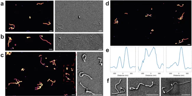
caSPIR Imaging of Viruses. To explore the potential of caSPIR in analyzing BNPs, we examined its ability to accurately characterize a heterogeneous mixture of Ebola virus-like particles (EBOV VLPs). Ebola virus is a highly pathogenic virus that has caused thousands of deaths and explosive outbreaks. The infected cells produce multiple Ebola virions, showing various shape and size distribution. Some virions are filamentous, 90 nm in width and 1 to multiple microns in length, and the others appear in circular, 6, or toroid shapes that can be 4−500 nm in diameter.40 The filamentous Ebola virion has been suggested to have a greater infectivity.8 For these reasons, direct high-resolution imaging of EBOV VLPs at high-throughput in a single experiment becomes highly desirable for accurate morphological character-ization. However, label-free visualization of these viruses in SPIR microscopy is even more challenging than fabricated nanostructures because their smaller size and lower refractive index lead to a much weaker contrast. Fortunately, the refined SPIR with asymmetric illumination provides simultaneous contrast and resolution enhancement with a high SNR ratio.
EBOV-VLPs were obtained using a transfection protocol as detailed in theMethodssection. To capture the EBOV-VLPs, we utilized a microarray printed on a SiO2chip surface (see Methods section). The microarray consists of ∼150 μm diameter antibody spots and negative control spots that capture the rVSV-EBOV and other viral glycoproteins, respectively. Before and after incubation, both positive and negative spots were imaged with conventional SPIR to ensure the specific binding. caSPIR clearly resolved the various EBOV structures and discriminated their morphological differences, consistent with the SEM images as shown inFigure 4. We also observed that EBOV VLPs could form branchedfilaments. The cross-section profiles in Figure 4e showed that caSPIR can distinguish closely separated (<200 nm) VLP structures and revealed both bent and straight VLP morphologies. Fur-thermore, caSPIR images showed a higher contrast at the tips
of the viral particles. This result was consistent with the classic “shepherd’s crook” shapes where increased mass creates locally high polarizability and thus leads to a more intense signal. Prior electron microscopy studies have shown that the ability to measure the length and density of EBOV virions correlates with the number of genomes incorporated,41 suggesting that caSPIR could be used to “count” the number of genomes incorporated into an Ebola virus particle.
We also imaged a leading Ebola virus vaccine candidate (rVSV-EBOV). This vaccine is a bullet-like (approximately 80 nm × 180 nm)23 recombinant vesicular stomatitis virus (rVSV) that expresses EBOV glycoprotein and can be captured for imaging by the same antibody used to capture and image EBOV VLPs. The rVSV-based vaccine candidates have shown great promise against Ebola disease and have been deployed to combat Ebola outbreaks in Africa.42 The promise of rVSV-vaccines brings with it a need to assess the quality of rVSV-vaccines produced for human use. In this context, characterizing the monodispersity of the rVSV-based vaccine candidates and its distinctive “bullet” shape along with an assessment of the genetic “payload” carried by a virion would aid vaccine development and quality assurance.
As demonstrated in Figure 5a, we were able to simultaneously visualize more than 1350 rVSVs-EBOV in the FOV at high resolution. Since this technique provides 150 nm lateral resolution, it can be utilized on denser samples that have more than 104particles in a FOV. As shown inFigure 5b,c,f,g, caSPIR enables the morphological characterization of rVSVs, which was previously not possible in SPIR microscopy. Although two rVSVs, indicated by a dashed circle in the caSPIR image (Figure 5d), appear to be spherical, they are mischaracterized as an elliptical structure with conventional SPIR (Figure 5h). This problem occurs because the back-ground artifacts are more pronounced in the conventional SPIR image reconstructions that recover the object from a single illumination configuration. The main background artifact sources include back-reflections from the optics and the surface roughness of the camera sensor glass and SiO2chip. Figure 4. caSPIR imaging of EBOV VLPs. (a−c) (Left) caSPIR images and (right) SEM images. SEM image area in (c) is indicated by a box. (d) caSPIR image. (e,f) (Left to right) Cross-section profiles indicated by dash lines in (d) and SEM images of the indicated VLPs, respectively. Scale bars are 1μm.
Over different illuminations, these artifact components remain stationary compared to the varying particle signal. Under multiple asymmetric illuminations, these static background artifacts become separated from the object’s signal and are greatly reduced. We note that the signal contrast from an individual virion under asymmetric illumination has a lower SNR when compared to conventional SPIR. Yet with multiple illuminations, caSPIR achieves ultrasensitive imaging of very small particles with high SNR. We anticipate that combinations of multiple low-NA illuminations from different parts of the back-pupil would allow for additional SNR improvement. Moreover, caSPIR offers a more informative means for distinguishing closely separated particles and thus prevents misleading morphological characterizations of individual virions in dense samples. The high-resolution images clearly discriminate two individual rVSV particles that were close enough to appear as a single elongated particle in conventional SPIR (compare arrows in the outsets inFigure 5d,e,h,i). With these improvements, the SPIR imaging platform enables accurate morphological characterization of thousands of individual viruses simultaneously.
CONCLUSION
This report demonstrated high-throughput direct visualization of low-index nanoparticles at subwavelength resolution. We formulated the vectorial PSF of the system by means of optical theory and implemented a computationally efficient linear inverse scattering approach. We demonstrated a 2-fold improvement in lateral resolution of the conventional SPIR and achieved lateral resolution of∼148 nm using visible light (420 nm) under a 100× /0.9 NA objective. This wide-field technique provided a large FOV of 100 μm × 100 μm, allowing for subwavelength imaging over 104 BNPs at once. We specifically focused on concept demonstration of this technique and its resolution capability using an artificial nanostructure sample fabricated by an EBL process. To demonstrate the biological relevance, we studiedfilamentous Ebola VLPs and a rVSV-based Ebola virus vaccine candidate as model viruses. These model viruses are surrogates of wild-type, clinically relevant pathogens. Namely, Ebola VLPs have been shown to closely resemble the Ebola virus,40 and the rVSV-EBOV resembles that of parent rhabdovirus.43In future work, we will evaluate the technique with wild-type viruses, but such a study requires a BSL4 laboratory and is beyond the scope of our present study. Conventional approaches for morphological characterization of viruses in solution use indirect methods
Figure 5. caSPIR imaging of rVSV Ebola model. (a) Full-FOV caSPIR image (∼1350 VSVs in the FOV). (b−e) Zoom-in areas indicated by arrows in (a) and (f−i) their conventional SPIR images, respectively. Scale bar in full-FOV (a) is 10 μm, and scale bars in zoom-in areas (b− i) are 300 nm.
such as fluorescent labeling, often relying on genetic modification of viral proteins.44 Historically, direct imaging of unmodified viruses has relied on laborious imaging techniques such as electron microscopy that can cause sample desiccation and degradation. Our low-cost light microscopy technique, caSPIR, enables high-resolution imaging of BNPs without any modification or sample preparation, thus allowing for analysis of clinical isolates directly.
We speculate that a path forward exists for improving SPIR’s resolution down to 100 nm. The source-function could be optimized for higher SPIR contrast, and high-NA objectives with a shorter wavelength light source could be utilized. Moreover, since the PSF model is vectorial, that is, it includes the polarization of fields, we speculate that a further enhancement for both contrast and resolution can be achieved by using polarization diversity. Similarly, polarization could also allow for better localization of rod-shaped metallic nanoparticles, for example, gold and silver.45 Especially, elongated nanoparticles show strong signal dependency with respect to the angle between the polarization axis and the particle’s long axis. The most significant improvement would perhaps be through optimization and automation of the imaging/acquisition system. In this study, the images were acquired by manually rotating the illumination mask, introducing a considerable delay between consecutive images and hence limiting the temporal resolution. Therefore, fully automated control of illumination configuration, for example, using a spatial light modulator in the illumination path, would enable dynamic measurements with a significant increase in spatiotemporal resolution. Such devices would also allow for the implementation of complex source functions including scanning individual or multiplexed low-NA illuminations across the back-pupil. To conclude, our study could enable exciting possibilities for high-throughput, ultrasensitive, and label-free imaging and characterization of a broad size spectrum of BNPs at high resolution. In particular, with the integration of the computational asymmetric illumination modality, this versatile wide-field interferometric microscopy techniqueSPIR microscopycould bridge the gap between scanning electron microscopy and conventional optical microscopy. Furthermore, the simplicity of our technique would allow other researchers to implement caSPIR with relatively minor modifications to their existing light micros-copy, thus, enabling a broad impact.
METHODS
Experimental Setup. The experimental setup for caSPIR is illustrated inFigure 1a. A partially coherent light sourceLEDwith spectral half-width of∼14 at 420 nm peak wavelength (Lumileds) is butt-coupled to an integrating sphere (Thorlabs). The coupled light undergoes multiple diffusive reflections on the entire sphere surface. Thus, the integrating sphere provides highly uniform, source-free, and spatially incoherent illumination. Note that the effect of integrating sphere on temporal coherence is quite negligible because it is reflectance spectrum is almost flat in a broad wavelengh range (250− 2500 nm). The custom-built circular sector aperture is mounted on a manual rotation mount (Thorlabs). The aperture is imaged into the back-focal plane of the microscope objective (Nikon, 100×/0.9 NA) in Köhler geometry with unit magnification. Under the conventional SPIR configuration, a graduated ring actuated iris diaphragm mounted on a cage plate is mounted to control the illumination NA. The layered substrate under observation is placed on a custom-built vacuum chuck mounted on a closed-loop piezo-z stage (Micronix). A tube lens (Thorlabs) images the sample onto a monocolor 12 MP CCD camera (Pointgrey) with 3.1μm pixel pitch to provide more
than twice the sampling rate required for Nyquist criterion,∼6.2 μm for 125 nm resolution.
PSF Calculations and Simulations. The physical model of SPIR was developed on custom-built MATLAB software using ASR formulation in the dipole limit where the size of the nanoparticle is much shorter the excitation wavelength.38The model calculates the SPIR image of a dipole scatterer placed near a planar surface using the vectorial formulation discussed in theResults and Discussionsection. We used a polarizability tensor of a silica nanosphere because silica has dielectric characteristics, that is, nonresonant and low-index, similar to BNPs. In the model, the spatially incoherent light-source with uniform intensity profile is imaged into the back-focal plane of the microscope objective in Köhler geometry. Each point in the back-pupil is assumed to have the same intensity. Thus, sample is uniformly illuminated within the angular spectrum of the system that is limited by the objective NA in epi-illumination. This is a valid assumption owing to the integration sphere which eliminates any structural attributes of the light source by reflecting each individual ray multiple times. The corresponding PSFs were calculated for a defined illumination geometry and system parameters. Note that the EBL sample has an 80 nm oxide layer in contrast to the other samples that are immobilized on 60 nm oxide chips. Thus, two sets of PSFs were simulated to be used in the reconstructions.
Image Acquisition and Reconstruction. A linear forward model, yj= Ajx + nj, was established using the vectorial SPIR model in
the Results and Discussion section, where yj denotes the observed
image, Ajdenotes the convolution operator associated with the shift
invariant PSF for a particular asymmetric illumination geometry of subscript j, x denotes the unknown underlying structure to be reconstructed, and nj denotes the unknown noise. The underlying
object can be estimated by minimizing the penalized least-squares cost function associated to Tikhonov regularization.
∑
α α ̂ = [∥ − ∥ ] + ∥ ∥ = x( ) arg min A x y x x j N j j 1 2 2 2 2Note that thefirst term in this optimization accounts for the data fidelity, and the second term captures prior information regarding image behavior, withα being a regularization parameter which trades off impact of the two terms. The closed-form solution of the Tikhonov regularized least-squares minimization problem can be expressed as ̂α = -α − ∑ [ * ] ∑ | + = = l m ooo n ooo | } ooo ~ ooo x( ) H Y H 1 j ( ) N j j j N j 1 1 2 , where - {·} −1 denotes the inverse Fourier operator, and H and Y denote the Fourier transforms of A and y, respectively. The raw images for asymmetric illumination were acquired by manually rotating the 60° circular sector aperture by 30° steps, resulting in 12 total images. After the asymmetrical illuminated images were acquired, the circular sector was replaced with a graduated-ring diaphragm to acquire conventional SPIR images. The conventional images were taken under low-NA (0.3) illumination. Then, the images were reconstructed in MATLAB using the aforementioned closed-form solution. The regularization param-eterα was empirically chosen by visual inspection to provide the best discrimination of the objects in the scene. To demonstrate its robustness, we generated reconstructions for values that are an order of magnitude larger and smaller than the tuned parameter (see
Supplementary Figure S4). These results indicated that the parameter
choice was not critical within the close interval of its nominal value. Moreover, as shown inSupplementary Figure S4, the results from the L-curve were consistent with the manually tuned parameter. The manually determined value fell on the corner of the L-curve for the Tikhonov regularization. Note that we first determined the regularization parameters for both caSPIR and conventional SPIR using the well-known EBL sample and then used the same parameters throughout all reconstructions. All of the images were taken under the 100×/0.9 NA objective unless otherwise stated.
Fabrication of Resolution Target. Nanostructure patterns were imprinted on SiO2substrate layered using electron beam lithography
80 nm SiO2 layer is formed on a silicon substrate by a
plasma-enhanced vapor deposition coating. Then, hydrogen silsesquioxane was spin coated as a resist material because it transforms into SiO2
after e-beam exposure. Nanostructure patterns were written on a sample using EBL, followed by immersion with a developer solution. Virus Creation, Preparation, and Use. Ebola VLPs were generated by transfection of HEK293FT cells with pCAGGS-based plasmids encoding each EBOV structural protein (GP, NP, VP30, VP35, VP24, VP40) except for the viral polymerase, L, together with a plasmid encoding the redfluorescent protein, mKate2, fused to VP40. The inclusion of mKate2-VP40 allowed visualization of particles by conventional fluorescence microscopy, and the amount used was optimized for VLP formation. Cells were plated in 10 cm culture dishes to 80% confluency 2 h prior to transfection. Each 10 cm dish was transfected with a total of 15μg of plasmid DNA using calcium phosphate.47 Transfection reagents were removed, and cells were washed with Dulbecco’s phosphate buffered saline (PBS) after 15 h, followed by addition of 10% fetal bovine serum containing DMEM. Cells were cultured at 95% humidity, 37°C, and 5% CO2for 48 h.
Culture medium was collected and clarified by centrifugation (1500×g) prior to concentration of VLPs by ultracentrifugation at 159,000×g for 2 h at 4 °C through a 10 mM HEPES buffered (pH 7.4) isotonic 8.2% sucrose cushion. Pellets were resuspended in Dulbecco’s PBS and banded through an isotonic iodixanol gradient to remove trace culture medium contaminants. Aliquots of banded VLPs were snap frozen in liquid nitrogen and stored at−80 °C until use.
VSV-based viruses that lack the endogenous VSV glycoprotein and express the Ebola virus glycoprotein from an independent tran-scription start/stop sequence placed in between the M and L genes of the VSV genome and were used in this study. Expression of Ebola virus glycoprotein was confirmed by Western blotting using glycoprotein-specific proteins. Virus stocks were prepared using Vero cells cultured in DMEM supplemented with 10% FBS, as described previously.48 Virus titers were determined by standard plaque assay methods and then diluted in PBS before the incubation. VLP amounts were assessed by Western blot of the Ebola virus glycoprotein.
Antibody Microarray Preparation and Assay Protocol. 60 nm SiO2 chips were coated with a solution of antifouling NHS
copolymer (Lucidant Polymers MCP-2) dissolved 1:100 in 1.2 M ammonium sulfate. Antibodies targeting the Ebola glycoproteins were spotted onto activated, polymer-coated chips, as were nonspecific antibodies (as controls) using the sciFLEXARRAYER S3 (Scienion AG). Chips were dried overnight and then washed with Tris-buffered saline + 0.1% Tween 20. Chips were then rinsed with Milli-Q water at least 6 times, removed from the dish at a 45° angle so that water wicks off the top surface, and then dried on a KimWipe with N2gas.49Chips
were scanned with a custom 1.5× magnification instrument (Nanoview Biosciences) to ensure the correct spot morphology. Note that since both EBOV VLPs and rVSV Ebola have the same surface glycoproteins, the same microarray preparation protocol is followed for each.
For virus loading, chips were placed in 24-well plates, etched-side up. 750μL of virus solution was added to the wells containing the chips, and the plates were put on an orbital shaker for 1 h at∼150 rpm. Chips were then removed from sample containing wells with forceps and placed in wells containing 0.1X PBS (Gibco 10010023) + 0.01% Tween 20, followed by washing on the orbital shaker for 5 min. This process was repeated twice, then the chips were placed in individual 60 mm dishes containing Milli-Q water and rinsed by swirling for a few seconds. Chips were dried by removing them from their dishes at a 45° angle, followed by placing them face-up on a KimWipe.
Scanning Electron Microscopy. Geometrical parameters of the nanopatterns in EBL and EBOV VLP sample were characterized using field emission scanning electron microscopy (FE-SEM). The EBL sample was inspected on FE-SEM (ZEISS, GeminiSEM 300) without any preparation process to preserve the sample. The EBOV VLP sample was coated with gold using a sputter coater (Cressington, 108) and imaged on a FE-SEM (ZEISS, Supra 55VP). Dimensions on the
SEM images were measured using SmartSEM image acquisition and analysis software.
ASSOCIATED CONTENT
*
sı Supporting InformationThe Supporting Information is available free of charge at https://pubs.acs.org/doi/10.1021/acsnano.9b08512.
Figure S1: Experimental validation of caSPIR. Figure S2: Circular sector angle sweep. Figure S3: Regularization parameter sweep. Figure S4: L-curve for the Tikhonov regularization. Figure S5: Fabrication non-uniformity in EBL sample. Figure S6: Conventional SPIR images of EBOV VLPs (PDF)
AUTHOR INFORMATION Corresponding Author
M. Selim Ünlü − Department of Electrical and Computer Engineering, Boston University, Boston, Massachusetts 02215, United States; Email:[email protected]
Authors
Celalettin Yurdakul− Department of Electrical and Computer Engineering, Boston University, Boston, Massachusetts 02215, United States; orcid.org/0000-0002-1755-4873
Oguzhan Avci− Department of Electrical and Computer Engineering, Boston University, Boston, Massachusetts 02215, United States; orcid.org/0000-0003-4104-4109
Alex Matlock− Department of Electrical and Computer Engineering, Boston University, Boston, Massachusetts 02215, United States
Alexander J. Devaux− Department of Microbiology and National Infectious Diseases Laboratories, Boston University School of Medicine, Boston, Massachusetts 02118, United States
Maritza V. Quintero− Department of Biochemistry and Structural Biology, University of Texas Health San Antonio, San Antonio, Texas 78229, United States
Ekmel Ozbay− Department of Electrical and Electronics Engineering, Bilkent University, 06800 Ankara, Turkey
Robert A. Davey− Department of Microbiology and National Infectious Diseases Laboratories, Boston University School of Medicine, Boston, Massachusetts 02118, United States
John H. Connor− Department of Microbiology and National Infectious Diseases Laboratories, Boston University School of Medicine, Boston, Massachusetts 02118, United States
W. Clem Karl− Department of Electrical and Computer Engineering, Boston University, Boston, Massachusetts 02215, United States
Lei Tian− Department of Electrical and Computer Engineering, Boston University, Boston, Massachusetts 02215, United States Complete contact information is available at:
https://pubs.acs.org/10.1021/acsnano.9b08512
Notes
The authors declare no competingfinancial interest. ACKNOWLEDGMENTS
Authors thank A. Y. Ozkumur for helpful discussion. This research was supported by the European Union’s Horizon 2020 research and innovation programme under grant agreement No. 766466 INDEX: Integrated nanoparticle isolation and detection system for complete on-chip analysis of exosomes. A.J.D. and J.H.C. were supported by National
Institutes of Health (NIH) (R21AI135517). R.A.D was supported by NIH (P01AI120943). M.V.Q. was supported by the NIH (5R25GM095480 and 5R01AI114814).
REFERENCES
(1) Stanley, S. Biological Nanoparticles and Their Influence on Organisms. Curr. Opin. Biotechnol. 2014, 28, 69−74.
(2) Geng, Y.; Dalhaimer, P.; Cai, S.; Tsai, R.; Tewari, M.; Minko, T.; Discher, D. E. Shape Effects of Filaments versus Spherical Particles in Flow and Drug Delivery. Nat. Nanotechnol. 2007, 2, 249−255.
(3) Wu, Y.; Deng, W.; Klinke, D. J., II Exosomes: Improved Methods to Characterize Their Morphology, RNA Content, and Surface Protein Biomarkers. Analyst 2015, 140, 6631−6642.
(4) Rejman, J.; Oberle, V.; Zuhorn, I. S.; Hoekstra, D. Size-Dependent Internalization of Particles via the Pathways of Clathrin-and Caveolae-Mediated Endocytosis. Biochem. J. 2004, 377, 159−169. (5) Bruckman, M. A.; Randolph, L. N.; VanMeter, A.; Hern, S.; Shoffstall, A. J.; Taurog, R. E.; Steinmetz, N. F. Biodistribution, Pharmacokinetics, and Blood Compatibility of Native and Pegylated Tobacco Mosaic Virus Nano-Rods and -Spheres in Mice. Virology 2014, 449, 163−173.
(6) Cooley, M.; Sarode, A.; Hoore, M.; Fedosov, D. A.; Mitragotri, S.; Gupta, A. S. Influence of Particle Size and Shape on Their Margination and Wall-Adhesion: Implications in Drug Delivery Vehicle Design Across Nano-to-Micro Scale. Nanoscale 2018, 10, 15350−15364.
(7) Welsch, S.; Kolesnikova, L.; Krähling, V.; Riches, J. D.; Becker, S.; Briggs, J. A. G. Electron Tomography Reveals the Steps in Filovirus Budding. PLoS Pathog. 2010, 6, e1000875.
(8) Campbell, P. J.; Kyriakis, C. S.; Marshall, N.; Suppiah, S.; Seladi-Schulman, J.; Danzy, S.; Lowen, A. C.; Steel, J. Residue 41 of the Eurasian Avian-Like Swine Influenza a Virus Matrix Protein Modulates Virion Filament Length and Efficiency of Contact Transmission. J. Virol. 2014, 88, 7569−7577.
(9) Vahey, M. D.; Fletcher, D. A. Low-Fidelity Assembly of Influenza a Virus Promotes Escape from Host Cells. Cell 2019, 176, 281−294.
(10) Nehls, J.; Businger, R.; Hoffmann, M.; Brinkmann, C.; Fehrenbacher, B.; Schaller, M.; Maurer, B.; Schönfeld, C.; Kramer, D.; Hailfinger, S.; Pöhlmann, S.; Schindler, M. Release of Immunomodulatory Ebola Virus Glycoprotein-Containing Micro-vesicles Is Suppressed by Tetherin in a Species-Specific Manner. Cell Rep. 2019, 26, 1841−1853.
(11) Balzarotti, F.; Eilers, Y.; Gwosch, K. C.; Gynnå, A. H.; Westphal, V.; Stefani, F. D.; Elf, J.; Hell, S. W. Nanometer Resolution Imaging and Tracking of Fluorescent Molecules with Minimal Photon Fluxes. Science 2017, 355, 606−612.
(12) Gustafsson, M. G. L. Nonlinear Structured-Illumination Microscopy: Wide-Field Fluorescence Imaging with Theoretically Unlimited Resolution. Proc. Natl. Acad. Sci. U. S. A. 2005, 102, 13081−13086.
(13) Shroff, H.; Galbraith, C. G.; Galbraith, J. A.; Betzig, E. Live-Cell Photoactivated Localization Microscopy of Nanoscale Adhesion Dynamics. Nat. Methods 2008, 5, 417−423.
(14) Rust, M. J.; Bates, M.; Zhuang, X. Sub-Diffraction-Limit Imaging by Stochastic Optical Reconstruction Microscopy (STORM). Nat. Methods 2006, 3, 793−796.
(15) Taylor, R. W.; Mahmoodabadi, R. G.; Rauschenberger, V.; Giessl, A.; Schambony, A.; Sandoghdar, V. Interferometric Scattering Microscopy Reveals Microsecond Nanoscopic Protein Motion on a Live Cell Membrane. Nat. Photonics 2019, 13, 480−487.
(16) Cheng, J.-X.; Xie, X. S. Vibrational Spectroscopic Imaging of Living Systems: An Emerging Platform for Biology and Medicine. Science 2015, 350, aaa8870.
(17) Horio, T.; Hotani, H. Visualization of the Dynamic Instability of Individual Microtubules by Dark-Field Microscopy. Nature 1986, 321, 605−607.
(18) Gaiduk, A.; Yorulmaz, M.; Ruijgrok, P.; Orrit, M. Room-Temperature Detection of a Single Molecule’s Absorption by Photothermal Contrast. Science 2010, 330, 353−356.
(19) Daaboul, G. G.; Gagni, P.; Benussi, L.; Bettotti, P.; Ciani, M.; Cretich, M.; Freedman, D. S.; Ghidoni, R.; Ozkumur, A. Y.; Piotto, C.; Prosperi, D.; Santini, B.; Ünlü, M. S.; Chiari, M. Digital Detection of Exosomes by Interferometric Imaging. Sci. Rep. 2016, 6, 37246.
(20) Young, G.; Hundt, N.; Cole, D.; Fineberg, A.; Andrecka, J.; Tyler, A.; Olerinyova, A.; Ansari, A.; Marklund, E. G.; Collier, M. P.; Chandler, S. A.; Tkachenko, O.; Allen, J.; Crispin, M.; Billington, N.; Takagi, Y.; Sellers, J. R.; Eichmann, C.; Selenko, P.; Frey, L.; et al. Quantitative Mass Imaging of Single Biological Macromolecules. Science 2018, 360, 423−427.
(21) Cheng, C.-Y.; Liao, Y.-H.; Hsieh, C.-L. High-Speed Imaging and Tracking of Very Small Single Nanoparticles by Contrast Enhanced Microscopy. Nanoscale 2019, 11, 568−577.
(22) Kukura, P.; Ewers, H.; Müller, C.; Renn, A.; Helenius, A.; Sandoghdar, V. High-Speed Nanoscopic Tracking of the Position and Orientation of a Single Virus. Nat. Methods 2009, 6, 923−927.
(23) Daaboul, G. G.; Lopez, C. A.; Chinnala, J.; Goldberg, B. B.; Connor, J. H.; Unlu, M. S. Digital Sensing and Sizing of Vesicular Stomatitis Virus Pseudotypes in Complex Media: A Model for Ebola and Marburg Detection. ACS Nano 2014, 8, 6047−6055.
(24) Avci, O.; Campana, M. I.; Yurdakul, C.; Ünlü, M. S. Pupil Function Engineering for Enhanced Nanoparticle Visibility in Wide-Field Interferometric Microscopy. Optica 2017, 4, 247.
(25) Avci, O.; Yurdakul, C.; Ünlü, M. S. Nanoparticle Classification in Wide-Field Interferometric Microscopy by Supervised Learning from Model. Appl. Opt. 2017, 56, 4238−4242.
(26) Sevenler, D.; Daaboul, G. G.; Ekiz Kanik, F.; Ünlü, N. L.; Ünlü, M. S. Digital Microarrays: Single-Molecule Readout with Interfero-metric Detection of Plasmonic Nanorod Labels. ACS Nano 2018, 12, 5880−5887.
(27) Scherr, S. M.; Daaboul, G. G.; Trueb, J.; Sevenler, D.; Fawcett, H.; Goldberg, B.; Connor, J. H.; Ünlü, M. S. Real-Time Capture and Visualization of Individual Viruses in Complex Media. ACS Nano 2016, 10, 2827−2833.
(28) Scherr, S. M.; Freedman, D. S.; Agans, K. N.; Rosca, A.; Carter, E.; Kuroda, M.; Fawcett, H. E.; Mire, C. E.; Geisbert, T. W.; Ünlü, M. S.; Connor, J. H. Disposable Cartridge Platform for Rapid Detection of Viral Hemorrhagic Fever Viruses. Lab Chip 2017, 17, 917−925.
(29) Ralston, T. S.; Marks, D. L.; Carney, P. S.; Boppart, S. A. Interferometric Synthetic Aperture Microscopy. Nat. Phys. 2007, 3, 129−134.
(30) Soto, J. M.; Rodrigo, J. A.; Alieva, T. Optical Diffraction Tomography with Fully and Partially Coherent Illumination in High Numerical Aperture Label-Free Microscopy. Appl. Opt. 2018, 57, A205−A214.
(31) Zhou, K. C.; Qian, R.; Degan, S.; Farsiu, S.; Izatt, J. A. Optical Coherence Refraction Tomography. Nat. Photonics 2019, 13, 794− 802.
(32) Zheng, G.; Horstmeyer, R.; Yang, C. Wide-field, High-Resolution Fourier Ptychographic Microscopy. Nat. Photonics 2013, 7, 739−745.
(33) Tian, L.; Li, X.; Ramchandran, K.; Waller, L. Multiplexed Coded Illumination for Fourier Ptychography with an LED Array Microscope. Biomed. Opt. Express 2014, 5, 2376−2389.
(34) Cotte, Y.; Toy, F.; Jourdain, P.; Pavillon, N.; Boss, D.; Magistretti, P.; Marquet, P.; Depeursinge, C. Marker-Free Phase Nanoscopy. Nat. Photonics 2013, 7, 113−117.
(35) Tian, L.; Waller, L. Quantitative Differential Phase Contrast Imaging in an LED Array Microscope. Opt. Express 2015, 23, 11394− 11403.
(36) Novotny, L.; Hecht, B. Principles of Nano-Optics; Cambridge University Press: Cambridge, 2006.
(37) Sevenler, D.; Avci, O.; Ünlü, M. S. Quantitative Interferometric Reflectance Imaging for the Detection and Measurement of Biological Nanoparticles. Biomed. Opt. Express 2017, 8, 2976−2989.
(38) Avci, O.; Adato, R.; Ozkumur, A. Y.; Ünlü, M. S. Physical Modeling of Interference Enhanced Imaging and Characterization of Single Nanoparticles. Opt. Express 2016, 24, 6094−6114.
(39) Mahamdeh, M.; Simmert, S.; Luchniak, A.; Schaeffer, E.; Howard, J. Label-Free High-Speed Wide-Field Imaging of Single Microtubules Using Interference Reflection Microscopy. J. Microsc. 2018, 272, 60−66.
(40) Bharat, T. A. M.; Noda, T.; Riches, J. D.; Kraehling, V.; Kolesnikova, L.; Becker, S.; Kawaoka, Y.; Briggs, J. A. G. Structural Dissection of Ebola Virus and Its Assembly Determinants Using Cryo-Electron Tomography. Proc. Natl. Acad. Sci. U. S. A. 2012, 109, 4275− 4280.
(41) Beniac, D. R.; Melito, P. L.; deVarennes, S. L.; Hiebert, S. L.; Rabb, M. J.; Lamboo, L. L.; Jones, S. M.; Booth, T. F. The Organisation of Ebola Virus Reveals a Capacity for Extensive, Modular Polyploidy. PLoS One 2012, 7, e29608.
(42) Henao-Restrepo, A. M.; Camacho, A.; Longini, I. M.; Watson, C. H.; Edmunds, W. J.; Egger, M.; Carroll, M. W.; Dean, N. E.; Diatta, I.; Doumbia, M.; Draguez, B.; Duraffour, S.; Enwere, G.; Grais, R.; Gunther, S.; Gsell, P.-S.; Hossmann, S.; Watle, S. V.; Kondé, M. K.; Kéïta, S.; et al. Efficacy and Effectiveness of an Rvsv-Vectored Vaccine Expressing Ebola Surface Glycoprotein: Interim Results from the Guinea Ring Vaccination Cluster-Randomised Trial. Lancet 2017, 389, 505−518.
(43) Ge, P.; Tsao, J.; Schein, S.; Green, T. J.; Luo, M.; Zhou, Z. H. Cryo-EM Model of the Bullet-Shaped Vesicular Stomatitis Virus. Science 2010, 327, 689−693.
(44) Brandenburg, B.; Zhuang, X. Virus Trafficking−Learning from Single-Virus Tracking. Nat. Rev. Microbiol. 2007, 5, 197−208.
(45) Taylor, A.; Verhoef, R.; Beuwer, M.; Wang, Y.; Zijlstra, P. All-Optical Imaging of Gold Nanoparticle Geometry Using Super-Resolution Microscopy. J. Phys. Chem. C 2018, 122, 2336−2342.
(46) Işil, Ç.; Yorulmaz, M.; Solmaz, B.; Turhan, A. B.; Yurdakul, C.; Ünlü, S.; Ozbay, E.; Koç, A. Resolution Enhancement of Wide-Field Interferometric Microscopy by Coupled Deep Autoencoders. Appl. Opt. 2018, 57, 2545−2552.
(47) Chen, C.; Okayama, H. High-Efficiency Transformation of Mammalian Cells by Plasmid DNA. Mol. Cell. Biol. 1987, 7, 2745− 2752.
(48) Garbutt, M.; Liebscher, R.; Wahl-Jensen, V.; Jones, S.; Möller, P.; Wagner, R.; Volchkov, V.; Klenk, H.-D.; Feldmann, H.; Ströher, U. Properties of Replication-Competent Vesicular Stomatitis Virus Vectors Expressing Glycoproteins of Filoviruses and Arenaviruses. J. Virol. 2004, 78, 5458−5465.
(49) Carter, E. P.; Seymour, E. Ç.; Scherr, S. M.; Daaboul, G. G.; Freedman, D. S.; Selim Ünlü, M.; Connor, J. H. In Ebolaviruses: Methods and Protocols; Hoenen, T., Groseth, A., Eds.; Springer: New York, 2017; pp 259−270.