Department of Electrical Engineering, Polytechnic University, Brooklyn, New York 11201 USA
AND J.A.LOCK
Physics Department , Cleveland State University, Cleveland, Ohio 44115 USA
Abstract.
Microcavities, such as microspheres, possess morphology-dependent resonances (MDR's) . In this chapter light coupling mechanisms to MDR's is examined. The novel mechanism of excitation of the microsphere with an optical fiber coupler (OFC) provides spatially and spectrally selective, as well as enhanced light coupling to the MDR's, when compared with the conventional plane wave excitation. The plane wave excitation is described by Lorenz-Mie Theory. However, Generalized Lorenz-Lorenz-Mie Theory and the Localization Principle are used for the OFC excitation.
1. Introduction
In recent years , the quantum confinement and localization effects in small scale systems have attracted substantial attention. Physical properties of these systems make them promising for applications in nonlinear optics and optoelectronic device physics . Avail-able examples are micrometer-size droplets, polystyrene microspheres, doped and undoped optical fibers , colloids, glasses doped with semiconductor microcrystallites, and quantum well, wire, dot, and superlattice structures. These structures have well characterized elec-tromagnetic properties, and due to their morphology they act as optical cavities at specific frequencies, thereby resulting in the localization of light, and affecting the dispersive prop-erties of the medium.
Microspheres, specially, continue to enjoy the attention of the optical spectroscopy community, because of their unique optical properties. [1] In the terminology of Photonic Band Gaps (PBG's), [2, 3] these microspheres are the equivalent of "Photonic Atoms", [4] since they can be used as a building block for the "Photonic Crystals" . [5]
237
T. Hakioglu and A.S.Shumovsky (eds.), Quantum Optics andtheSpectroscopy ofSolids, 237-248. © 1997Kluwer Academic Publishers.
238 A.SERPENGUZEL ET AL .
(b) Non resonant Plane Wave
MDR
o
MDR
---I~~ (a) Resonant Plane Wave
~
(c) Resonant Gaussian Beam (d) Non resonant Gaussian Beam
O
MDR - - . .~~O
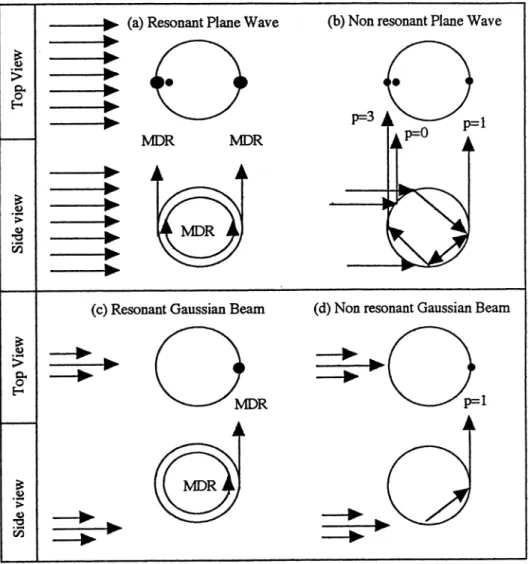
p=1Figure 1. Schematic of the top and side views of the microsphere depicting the non- resonant (p=O ,1,3) glare spots and MDR glare spots when excited by (a) a resonant plane wave, (b) a non-resonant plane wave, (c) a resonant off-axis Gaussian Beam, and (d) a non-resonant off-axis Gaussian Beam . Note that the glare spots are not totally correlated with the internal intensity distributions.
The curved interface of the microsphere is responsible for three electromagnetic and quantum-electrodynamic (QED) effects . First, for a plane wave illumination, the internal intensity is concentrated along the principal diameter near the front and the back surfaces of the microsphere (Fig. l(b) and Fig. 2).
enhance-Y/
q
Figure 2. The internal input-laser intensity distribution in the equatorial plane of the droplet for a plane-wave input (off resonance) propagatinginthe x-direction with size parameter x =418 and N=1.36 .
ment of approximately lOOX (and lOX) is expected in the localized region just within the droplet shadow (and illuminated) face. These intensity enhancement factors increase with the droplet radius, because more of the incident radiation is intercepted by the droplet illuminated face or hemisphere. Second, the microsphere acts as an optical cavity for spe-cific wavelengths, which satisfy the morphology-dependent resonance (MDR) condition . MDR's can be considered as standing waves, which may be decomposed into two
coun-240 -1 A.SERPENGUZEL ET AL. \ .OJ)
1 ."\.
Figure3. The internal intensity distribution in the equatorial plane of the droplet for a plane-wave input [on an input (TE) resonance] propagating in the x-direction with N=1.59 , x=18.83. The maximum value of the internal intensity is 159.
terpropagating waves traveling around the microsphere rim (Fig. l(a) and Figs . 3-4) . The counterpropagating traveling waves must experience quasi-total-internal reflection repeat-edly at the spherical droplet interface and return to the starting point with their initial phase. For wavelengths that are on MDR's and within the medium's gain profile, the gen-erated output waves circulate around the droplet rim and experience gain at the two high internal intensity regions. Occasionally, when the monochromatic input-laser frequency is
.1 .\.
Figure4. The internal intensity distribution in the equatorial plane of the droplet for a MDR [an output (TE) resonance] with N=1.59 and x =18 .83. Notice that the internal intensity due to the focusing of the plane wave input of the Fig . 3ismissing, and the maximum value of the internal intensity is 49 as opposed to 159 of Fig. 3.
tuned to a MDR (an input resonance), there can be an even larger enhancement the input intensity (Fig . 4) . Third, the optical transition cross-sections in the microspheres can be larger than bulk optical transition cross-sections, because of the modified density of final electromagnetic states. (6) In the microsphere, the final electromagnetic states correspond to the microsphere cavity resonances, which are described by MDR's. For a bulk sample,
242 A .SERPENGUZEL ET AL.
however , the final electromagnetic states are the continuum modes of an infinite system . [7,8]
The SRS threshold for a water microdroplet is lower than that of water in an 11-em optical cell.[9] In addition, these three effects are responsible for the occurrence of a number of other nonlinear optical effects such as stimulated anti-Stokes Raman scatter-ing (SARS),[10] coherent anti-Stokes Raman scatterscatter-ing (CARS),[11] stimulated Brillouin scattering (SBS),[12] third-harmonic generation (THG),[13, 14] and lasing [15, 16, 17] in microdroplets .
Ifthe incident plane wave is resonant with a MDR (i.e., on-resonance), there will, in addition , be a uniform intensity distribution within the rim of the microsphere in the volume determined by the MDR (Fig. l(a)) . [18] However, if an off-axis Gaussian beam is used at a resonant wavelength, the internal intensity is only dist ributed within the rim of the microsphere in the volume determined by the MDR, and is no longer concentrated near the front and the back surfaces of the microsphere (Fig. 1(c)) . [19] Therefore, a resonant off-axis Gaussian beam excites the MDR's more uniformly and more efficiently than a plane wave. Even edge illumination with a focused beam excites MDR's more efficiently than plane waves (Fig. 1(d)). [20, 21] The off-axis Gaussian beam calculations have recently been realized using generalized Lorenz-Mie theory (GLMT). [22,23]
2. Experiments
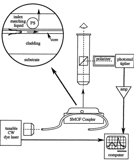
The first experimental realization of the off-axis Gauss ian beam excitation geometry was performed by using an optical fiber coupler (OFC) . [24] The frequen cy shift and linewidth broadening of the MDR's due to the OFC -microsphere interaction were also studied. [25] In these OFC- microsphere experiments the cladding of the fiber was not index matched to the media surrounding the microsphere, so that there was an optical interface at the OFC surface. In this chapter, we describe the excitation of the MDR's of a micro sphere resting on the surface of an OFC , whose surface has been wetted with an index matching oil to eliminate the air- fiber interface. Thereby, the beam in the optical fiber effectively becomes the equivalent of a Gaussian Beam with an infinitely long skirt length .
Figure 5 is a schematic of our experimental setup. A polystyrene (P S) micro sphere with an approximate radius a
=
12 p,m and refractive index N=
1.59 is placed on an OFC. The OFC is made from a single-mode optical fiber (SMOF) with a core diameter of 3.8 pm (N=
1.462), and a cladding diameter of 125 p,m (N=
1.457). The cladding below the microsphere is shaved down to 0.7ut«.
The SMOF mode has approximately a Gaussian intensity profile and is doubly degenerate with both horizontal and vertical polarizations. The OFC surface and the microsphere were wetted by a few millimeters of index matching oil (N=
1.456, same as the cladding). The excitation is provided by a tunable and linearly polarized CW dye laser with a linewidth of 0.025 nm. The dye laser is coupled to the SMOF with a microscope objective. Although the output of the dye laser was linearly polarized , the output from the SMOF was observed to be elliptically polarized due to the fiber birefringence . Therefore, the OFC provides both linear polarizations to the microsphere. The scattering from the microsphere was collected at 900 with a micro scope objective followed by a polarizer, and detected with a photomultiplier tube.Ifplane wave illumination were used, the image of the microsphere (either on resonance or off resonance) would show three principal glare spots (Fig. l(a-b )) . [26] However, in our
I I I
,
I I,
I0-
p'9~e!.1
1
tunable CW dye laserI---...
~
photomul tiplier computerFigure5. Schematic of the experimental setup with inset to depict the microsphere on the wetted surface of the SMOF coupler.
case of coupling an external beam from the SMOF , we observe only one glare spot on the far side of the microsphere (Fig. l( c» . In contrast to the non-index matched case, this far side glare spot is observed for all laser wavelengt hs, even when t he incident wavelength is not on a MDR (i.e. , off-resonance). However, when the incident light is on-resonance, the far side glare spot intensity is enhanced by a factor of about 2. App arently, the standing wave pattern which was set up by a plane wave excitation of a MDR, with its counterpropagat ing traveling waves (Fig. l (a», is replaced wit h a single counter-clockwise traveling wave in
244 A .SERPENGUZEL ET AL.
the Gaussian beam excitation (Fig. 1(c)). Also, in the Gaussian beam excitation (Fig. 1(c-d)), the off-resonance glare spots are due to refraction only (i.e., p=1 rays) , while for a plane wave illumination the off-resonance glare spots are due to both refraction (i.e ., p=1 ,3 rays) and specular reflection (i.e. , p=O rays).
3. Theory of off-axis Gaussian beam excitation
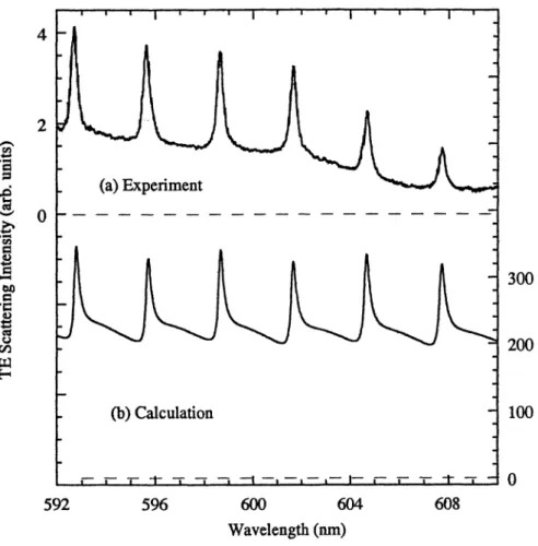
Figure 6(a) displays the experimentally observed transverse electric (TE) scattering spec-trum from the microsphere excited with the OFC. Figure 6(b) depicts the theoretically calculated TE scattering spectrum for an off-axis Gaussian beam placed at the location of the OFC. Comparing the spectra in Fig. 6 to the scattering spectra obtained with a plane wave, one notices two features: (1) there is a large background intensity, which cannot be explained by the light scattered due to OFC surface imperfections; and (2) t he MDR's have nearly Lorentzian lineshapes as opposed to the Fano lineshapes [27) of the plan e wave scattering spectra. Most of the prominent features of these scattering spectra are described by the interaction of the microsphere with an external beam having a Gaussian intensity profile and propagating at an impact parameter (b) , which is slightly greater than the microsphere radius (a). Since the excitation by such a beam occurs beyond the edge of the microsphere, t he light sca ttering can be calculated by (i) removing the partial waves with angular momentum quantum numbers (n) less than the size parameter (x , which is the ratio of the perimeter of the microsphere to the incident light wavelength) from the conventional Lorenz-Mie (plane wave excitation) infinite series, and (ii) applying generalized Lorenz-Mie theory (GLMT) to parametrize the incident beam profile . This removal of partial waves is justified by the localization principle, [28) which associates a light ray having an impact parameter (b) with a partial wave with mode number (n) .
Plane wave Lorenz-Mie theory restricts the angular momentum quantum number (n) range of the light rays, passing by the microsphere surface but yet interacting with it , to have their mode number (n) between x and Nx, where N is the relative refractive index of the microsphere with respect to the outside medium. This condition , together with the localization pr inciple, restricts the impact parameter (b) range to be between a and Na. Therefore, only the light rays within this impact parameter range can couple to the MDR's of the microsphere.
To check the validity of this approach and to simulate our experimental results of Fig. 6(a) , we have used the GLMT computation algorithm, [29) which can be applied to on- and off-axis focused Gaussian beam excitation geometries. In GLMT , the plane wave expansion coefficients(anfor TM orbnfor TE resonances) are replaced by the partial wave expansion coefficients (an m for TM coefficients or bn m for TE coefficients). For example
for TE contributions, bn m = bn Bn m , where Bn m describes the angular overlap of the
excitation field and the spherical harmonics.
For our external off-axis Gaussian beam excitation geometry,Bn m become significant
as n exceeds x . As n is increased further, Bn m goes through a series of resonances (i.e .,
MDR's), with none seen beyond n=Nx. The background in the spectra of Fig. 6(b) is due to the refraction for non -resonant partial waves with njx. For a plane wave excitation,
Bn m would have been significant for all n. For the calculations of Fig . 6(b), we used a
Gaussian beam (with an infinite skirt-length and a beamwaist with a half-width Wo
=
2.176 /-lm) propagating at an impact parameter of 14.94 /-lm from a microsphere (with
(a) Experiment 2
o
(b)Calculation300
200100
o
592 596 600 604 Wavelength (om)608
Figure 6. Scattering intensity of (a) experimental, and (b) calculated TE polarized spectrum for a PS microsphere in index matching liquid (N=1.456).
intensity is averaged over the scattering angle around 900
• The results of this calculation
are compelling. The theoretical MDR's for an off-axis incidence bear a good relationship to the experimental data [Figs. 6(a)l, and appear to correspond to first order MDR's with theoretical quality factors (Q 's) of approximately 2000. The mode numbers (n) for the MDR's are within the range of n
=
194 -198.246
10
5
o
A.SERPENGUZEL ET AL.(a) Experiment
(b)
Calculation
10
5
595
600
605
610
Wavelength (nm)
o
615
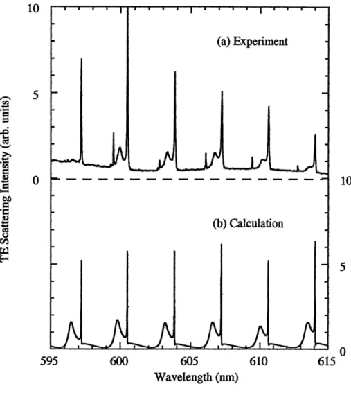
Figure 7. Scattering intensity of (a) experimental, and (b) calculated TE polarized spectrum for a PS micros ph ere in water (N=1.18) .
placed to maximally excite these MDR's with n
=
194 -198. We obtain b=
nJk=
12.9J.Lm , which is smaller than our experimental value of b
=
14.94J.Lm. Therefore, we are not coupling to these MDR's with n=
194 -198 with maximal efficiency. Different mode numbers are excited at different impact parameters. For our modes with n=
194-198, in accordance with the localization principle, the maximum of the scattering efficiency occurs at an impact parameter of 12.9J.Lm . At our impact parameter of 14.94J.Lm, theand the excitation electric field being evanescent rather than being Gaussian , it is possible to have modes with higher measured Q's of 24000. Figure 7(a) shows the experimental elastic scattering intensity of the TE polarized spectrum for a PS microsphere in water (N
=
1.18), while Figure 7(b) displays the corresponding calculated spectrum. A notewor-thy feature of the spectra in Fig. 7(a) is that, MDR's with linewidths as narrow as 0.04 nm were observed . Since our dye laser has a linewidth of 0.025 nm, the measured MDR linewidths are clearly limited by the convolution of our dye laser linewidth .4 . Conclusion
In conclusion , the microsphere-optical fiber system with the index matching geometry has proved to be very useful in the verification of the generalized Lorenz-Mie theory (GLMT) and t he localization pr inciple. The microsphere-optical fiber system also shows promise as a possible building block for photonic memories , [30] and can be used as an external cavity feedback system to line narrow a broader light source such as a diode laser . [31,32] Acknowledgements
We are grateful for the partial support of this research from the United States Air Force Office of Scientific Research (Gra.nt Number F49620-94- 0195).
248
References
A.SERPENGUZEL ET AL .
I. P. W . Barber and R. K. Chang, Eds ., Optical Effects Associated with Small Particles (World Scient ific 1988) Singapore.
2. E. Yablonovitch, Phys. Rev. Lett. 58, 2059 (1987).
3. C. M. Soukoulis, Photonic Band Gaps and Localization (Plenum Press 1993) New York.
4. S. Arnold, J . Comuna.le, W .B. Whitten , J.M. Rams ey, and K.A. Fuller , J . Opt. Soc. Am . B 9 819 (1992) .
5. W . Hu, H. Li, B. Cheng , J . Yang, Z.
u,
and D. Zhang , Opt. Lett. 20 964 (1995) . 6. E. M. Purcell, Phys. Rev. 69 681 (1946) .7. S. C. Ching , H. M. Lai, and K. Young, J . Opt. Soc. Am . B 4 1995 (1987) . 8. S. C. Ching, H. M. Lai, and K. Young, J . Opt. Soc. Am . B 4 2004 (1987). 9. J .B.Snow , S.-X .Qian, and R.K.Chang, Opt. Lett . 10 37 (1985).
10. D.H . Leach, R.K .Chang, and W .P . Acker , Opt. Lett . 17387 (1992). II. S.-X .Qian, J.B .Snow, and R.K .Chang, Opt. Lett . 10 499 (1985). 12. J .-Z. Zhang and R.K.Chang, J . Opt. Soc. Am . B 6 151 (1989). 13. W .P . Acker , D.H . Leach, and R.K .Chang, Opt. Lett . 14402 (1989). 14. D.H . Leach , W .P . Acker, and R.K.Chang, Opt. Lett. 15 894 (1990).
15. H.-M . Tzeng, K.F . Wa.ll, M.B. Long , and R.K .Chang, Opt. Lett. 9 499 (1984). 16. S.-X .Qian, J .B.Snow , H.-M. TzEng, and R.K.Chang, Science 231 486 (1986) . 17. H.-B.Lin, A.L.Huston, B.L.Justus, and A.J .Campillo, Opt. Lett . 11 614 (1986) .
18. D.S. Benincasa, P.W . Barber, J .-Z. Zhang , W.-F . Hsieh, and R.K . Chang, Appl. Opt. 26 1348 (1987). 19. E. E. M. Kha.led, S. C. Hill, and P. W . Barber, Appl. Opt . 33 524 (1994).
20. J . -Z. Zhang, D. H. Leach , and R. K. Chang, Opt. Lett . 13 270 (1988).
21. J . P. Barton, D. R. Alexander, and S. A. Schaub, J. Appl . Phys . 64 1632 (1988) . 22. J . A. Lock and G. Gouesbet, J . Opt. Soc. Am . A 11 2503 (1994).
23. G. Gouesbet and J . A. Lock, J . Opt. Soc. Am. A 11 2516 (1994) . 24. A. Serpengiizel, S. Arnold, and G. Griffel, Opt. Lett . 20 654 (1995).
25. N. Dubreuil, J .C . Knight , D.K. Leventha.l, V. Sandoghar, J. Hare, and V. Lefevre , Opt. Lett. 813 20 (1995) .
26. S. Arnold , S. Holler, J . H.
u,
A. Serpengiizel, W. F. Auffermann, and S. C. Hill, Opt. Lett. 20 773 (1995) .27. P. W . Barber and R. K. Chang, Eds ., Optical Effects Associated with Small Particles (World Scientific 1988) Singapore, p.20.
28. H. C. van de Hulst , Light Scattering by Small Particles (Dover, 1981) New York, p. 208. 29. J . A. Lock, Appl. Opt. 34 559 (1995) .
30. S. Arnold , C. T . Liu, W . B. Whitten and J. M. Ramsey, Opt. Lett. 16420 (1991).
31. G. Gr iffel, A. Serpengiizel, and S. Arnold , "Quenching of semiconductor lasers linewidth by detuned loading using spherica.l cavities morphology dependent resonan ces," Proceedings of the IEEE: Fre-quency Control Conj., San Francisco, CA, USA (1995).
32. G. Griffel, S. Arnold, D. Taskent , A. Serpengiizel , J. Connolly, and N. Morris , Opt. Lett. 21 695 (1996) .

![Figure 3. The internal intensity distribution in the equatorial plane of the droplet for a plane-wave input [on an input (TE) resonance] propagating in the x-direction with N=1.59 , x=18.83](https://thumb-eu.123doks.com/thumbv2/9libnet/5928219.123216/4.723.102.613.157.680/figure-internal-intensity-distribution-equatorial-resonance-propagating-direction.webp)
![Figure 4. The internal intensity distribution in the equatorial plane of the droplet for a MDR [an output (TE) resonance] with N=1.59 and x =18 .83](https://thumb-eu.123doks.com/thumbv2/9libnet/5928219.123216/5.723.112.632.175.691/figure-internal-intensity-distribution-equatorial-droplet-output-resonance.webp)