CBÜ Fen Bil. Dergi.,Cilt 12, Sayı 2, 159-166 s CBU J. of Sci., Volume 12, Issue 2, p 159-166
159
Detection of Delaminations of Laminar Composites
by Infrared Thermography
Ömer Sinan Şahin1*, Murat Selek2
1Selçuk University, Engineering Faculty, Mechanical Engineering Department, Selçuklu, Konya, +90 332
2231827, [email protected]
2Selçuk University, Vocational School of Technical Sciences, Selçuklu, Konya, +90 332 2232373
*Corresponding author / İletişimden sorumlu yazar Received / Geliş: 6th February (Şubat) 2015
Accepted / Kabul: 15th June (Haziran) 2015
DOI: http://dx.doi.org/10.18466/cbujos.91945
Abstract
The laminar composite materials may lost their bending stiffness and strength by formation of the delamination during production and service. However, these delaminations can be barely visible by the naked eye and thus the damage detection of composites materials is inspected generally in laboratory. In this study, the in situ detection of the delamination in laminar composite materials was investigated by using infrared thermography approach. First the composite materials were subjected to low velocity impacts to create arbitrary delamination. Then, these composites materials were exposed to cyclic bending loading and observed by using a thermal camera. The temperature variations caused by the friction within delaminated field have been investigated. It is shown that the delamination damages under cyclic loads cause to a serious internal friction and the delamination can be detected by infrared thermography.
Keywords— Infrared thermography, image processing, laminated composites, delamination, cyclic loading.
1 Introduction
The detection of the damage accumulation and crack nucleation in materials has great importance in practi-cal applications [1] since the structural defects general-ly cannot be detected until they became visible by the naked eye unless any non-destructive tests are ap-plied.
Composite materials have unique damage modes which can form under static, impact or cyclic loading. For example, the laminated composites are susceptible to delamination frequently caused by impact loading during manufacturing, service and maintenance. These damage modes are matrix damage, fiber dam-age, fiber/matrix debonding and delamination be-tween successive plies. These damage types are gener-ally invisible by naked eye. The above mentioned damage types can result in dramatic decrease in
strength, fatigue life and flexural properties such as bending stiffness and bending strength [2]. This situa-tion is very important especially for machine parts working under cyclic loading. So, it is very important to detect whether these type of damages have formed or not. On the other hand, these types of damages generally form while material works in service. Due to size and dimension limitations and transportation difficulties these types of materials are generally not tested in laboratory. So, the damage detection should generally be performed in situ.
In this situation, non destructive testing methods such as acoustic emission, ultrasonic and x-ray can be used. However, these techniques require specimens prepa-ration [3] and not suitable for testing of a machine element while working except for acoustic emission technique. However, acoustic emission technique is
CBÜ Fen Bil. Dergi.,Cilt 12, Sayı 2, 159-166 s CBU J. of Sci., Volume 12, Issue 2, p 159-166
160 not suitable for damage size evaluation.
In case of cyclic bending loading, the delaminated field within material creates friction between match-ing surfaces by the shear motion which leads to the heating of the delaminated field. The heating at the delaminated surfaces results in temperature increase at the surface of the material enabling us to detect delaminated zones within material by using an infra-red (IR) camera. Some authors [4-6] reported that de-fects, fatigue cracks can result in rapid temperature increase. It is also reported that when the material is subjected to external loads, some of the energy ap-plied is converted into heat by the material [7]. Meola and Carlomagno used the infrared thermography (IRT) for determine the response of composite materi-als under impact loading [8, 9]. They showed that thermal events during impact loading can be visual-ized by IRT.
IRT is a non contact technique that enables us to cap-ture invisible thermal radiation from stationary or moving objects at any distance and obtain their tem-perature maps [10, 11]. In this technique, specimen preparation is not needed and no practical limitations on dimensions and shape. So, the IRT perfectly suita-ble for in-situ damage detection of laminar composites [11]. This technique enables also the user to get rec-orded data for in-situ and instant damage detection. Nowadays, the developments of IRT have also ena-bled the scientists to investigate the fatigue of metals by using this technique [12-14].
Active IRT was utilized for impact damage in carbon fiber composites [15-17] and glass-fiber composites [18]. IRT was also utilized for damage detection [19-22] and fracture toughness evaluation under static or fatigue loading [15, 16, 23, 24].
In this study, the IRT was used for in-situ delamina-tions detection in laminar composites. Delaminated zones have been created by the application of impact loading at different impact velocities. It is shown that invisible delaminations can be detected by applying cyclic loading while surface temperatures of the mate-rials measured instantly during the working period and the variation of surface temperatures can be de-termined as an indicator of damage formation.
2 Theory of Heat Generation under Cyclic
Load-ing
It was shown by many authors that the temperature increase in material due to cyclic loading can be
divid-ed into three characteristic stages as follows [25],
Initial thermal gradient,
Temperature stabilization (steady state),
Final rapid temperature increase.
Curti et al. [26] also showed that the fatigue limit can be correlated to the initial thermal gradient stage and to the temperature stabilization (steady state) stage [13, 27, 28].
The overall mechanical energy input to the test speci-men under cyclic loading can be written as [29],
∫ (∮ σ
V ij. dε
ij). f. dV
(1)
where V is volume of the control, σ and ε represents the stress and strain constituents respectively. Here,ij
is stress tensor,
ij is strain tensor and f representsthe cyclic loading frequency in Hertz. Damage for-mation in terms of matrix cracking, fiber failure and fiber/matrix interface debonding can affect the stress and strain distribution within material and also affect the heat input expressed in Equation (1). However, the most significant heat input is obtained due to delami-nations.
In case of delaminations, it results in friction between mating surfaces under cyclic loading. The dissipated energy due to friction is caused to heat generation and temperature increase. The heat (generation) input due to friction can be expressed as follows.
P = F
Fr. V
avg(2)
Where FFr and Vavg represent the friction force and the
average relative velocity between the delaminated surfaces, respectively. Since the cycling loading ap-plied as sinusoidal, the relative displacement between adjacent surfaces can be expressed as follows.
𝛆(𝐭) = 𝛆
𝐦𝐚𝐱. 𝐒𝐢𝐧(𝛀𝐭)
(3)
Where max is maximal displacement between adjacent
surfaces at delaminated field and is the cyclic load-ing frequency in rad/sec. Hence the average velocity can be expressed as follows.
V
avg=
∆ Δt=
1 T∫ |
. ε
max. Cos(
t)|
T 0= 4. ε
max. f
(4)
Where f represents the cyclic loading frequency in Hertz. By using above equations the heat generation
CBÜ Fen Bil. Dergi.,Cilt 12, Sayı 2, 159-166 s CBU J. of Sci., Volume 12, Issue 2, p 159-166
161 rate by friction at delaminations can be expressed as follows.
q
ı=
P ADZ=
4.εmax.f.F.μ
ADZ
(5)
Where qı represents heat flux by means of the
friction-al heat generation over delaminated zone (ADZ) and μ represents friction coefficient between mating sur-faces. So, an additional heat generation due to friction between delaminated surfaces can be expressed as following equation.
q = ∫
(∮
q
lADZ
. dA
DZ)
(6)
The mechanical energy dissipates as heat transfer by conduction, convection and radiation energy while the remaining is dissipated by the variation of the internal
energy and stored energy of cold work (
.
p
E
). So, the global heat equation of a material with delaminations can be expressed as follows.
∫ (∮(𝜎𝑖𝑗
𝑉. 𝑑𝜀
𝑖𝑗). 𝑓. 𝑑𝑉 + ∫
𝐴𝐷𝑍(∮ 𝑞
𝑙. 𝑑𝐴
𝐷𝑍) =
∫ −𝜆. ∇
𝑉 2T. dV + ∫
SCVα. (T − T
∞). dS
CV+
∫
SIRκ. σ
n. (T
4− T
∞4). dS
IR+
∫ (ρ. c.
dT dt+ E
ṗ dV
)
V(7)
The left side of the equation represents the overall energy input during cyclic loading. The first term at right side of the equation is ∫ −λ. ∇2T. dV
V which
rep-resents the heat conduction. Where,
is thermal con-duction coefficient.The second term is ∫SCVα. (T − T∞). dSCVwhich repre-sents the convectional heat transfer. Where,
is the convection heat transfer coefficientS
CV is the area subjected to convectional heat transfer and T is am-bient temperature.The third term at right side is ∫ κ. σSIR n. (T4− T∞4). dSIR which represents the heat transfer by radiation. Here,
n
is Stephan-Boltzmann coefficient
is surface emissivity and SIR is the area subjected to heat trans-fer by radiation.The last term ∫ (ρ. c.dT
dt+ Eṗ dV)
V consists of two terms.
One is the variation of internal energy and the second is critical energy level. Where,
is density, c is specif-ic heat of the material and, Eṗ is critical energy level at the fracture.3 Expreimental Study
The tested material is 8 plied E-glass/epoxy unidirec-tional composite plates with fiber volume fraction of 80% (Fig.1.b). The mechanical properties of the con-stituents and the testing specimens are presented in Tables 1 and 2 respectively. Low velocity impact tests were performed under simply supported boundary condition while the impactor mass is 15 Kg. Therefore, the impact tests were conducted for three different velocities as 1 m/s, 1,25 m/s and 1,5 m/s.
Table 1. Mechanical properties of the reinforcement and the matrix.
E (GPa)
TS (MPa)
(g/cm3) Ɛmax (%)Reinforce-ment (E-glass)
73 2400 2,6 4-5
Epoxy 3,4 50-60 1,2 1,5-2
Table 2. Properties of specimens.
Property Value
Strength (MPa) (Longitudinal) 632 Strength (MPa) (Transverse) 68
Poisson’s ratio 0,19
Fiber volume fraction (%) 800,6 Longitudinal Elasticity Modulus (MPa) 1040 Transverse Elasticity Modulus (MPa) 201 The test specimens were first subjected to low velocity impacts by 15 kg under impact velocity of 1 m/s, 1,25 m/s and 1,5 m/s which create 7,5 Joule, 11,7 Joule and 16,8 Joule respectively. Then, the one end of the test specimen is clamped and the other end is moved by an adjustable crank which is driven by an electrical engine running at 25 cycle/sec. The test stand is shown in Fig.1.a. The end displacement (δ) of the test speci-men can be adjusted by crank rig. So, the cyclic loads were applied as ±4 mm, ±5 mm and ±6 mm end dis-placements respectively. The experimental setup of the IRT used to obtain thermal images is shown in Fig.2. The properties of FLIR E45 IR camera used in study are presented in Table 3.
CBÜ Fen Bil. Dergi.,Cilt 12, Sayı 2, 159-166 s CBU J. of Sci., Volume 12, Issue 2, p 159-166
162 a)
b)
Figure 1. a) Schematic drawing of measuring system b) test specimen.
Figure 2. The experimental setup of the IRT. Table 3. Properties of FLIR E45 IR camera.
Detector Type Focal Plane Array (FPA), Uncooled Mi-crobolometer 160x120 Pixels
Spectral Range 7,5 to 13 μm Temp. Range -20 ˚Cto +250 ˚C Thermal Senst. 0.1 ˚C at 30 ˚C
Video Output Standard RCA Composite Video Image Freq. 50/60 Hz
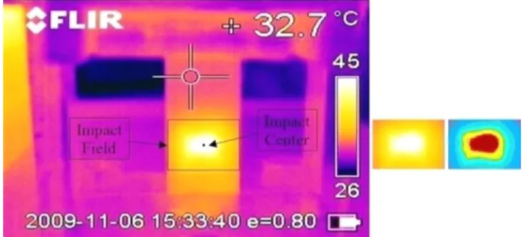
FOV / Min. Typical 34˚x25˚/0.1m (with 9,2 mm lens) During cyclic bending loading test, the thermal imag-es were obtained by FLIR E45 IR camera for 30 minutes under different loading levels (see Fig.1). Meanwhile, the thermal images of the composite ma-terial were recorded at sampling rate of 30 frames per second (33 ms interval). Primarily, to both reduce the data to be processed and shorten the processing time, the delamination field which will be examined is de-termined at the each thermal image as shown in Fig.3. Then, the temperature values of the impact center and
the temperature distributions of the delamination field are obtained by applying the method suggested M. Selek et al [13] to thermal image of this field. Starting from the highesttemperature value obtained in the experiments, the contour images of the delamination field were obtained from its temperature distribution at intervals of 1 ºC. These processes are showed in Fig.3.
Figure 3. The thermal and contour images of the impact center and the delamination field.
4 Results
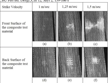
The visible damage formation of test specimens is shown in Fig.4. As seen in this figure, when the spec-imens subjected to impact loading, visible and invisi-ble damage can form. However, that delamination is generally invisible.
After the impact loading, the specimens were fixed at bending fatigue test stand and tested under different cyclic loads. The impact loading can create matrix cracks and delamination in the specimen. Due to the formation of these damages, the internal friction local-ize on that regions especially mating surfaces of de-laminated fields. This situation creates considerable amount of the internal friction under cyclic loading which can be observed as temperature increase. So, these regions are expected to be seen in higher tem-peratures in comparison with undamaged regions. Since the test materials have been previously subject-ed to impact loading, while under bending fatigue, only the impacted region has been observed by IR camera as shown in Fig.3.
CBÜ Fen Bil. Dergi.,Cilt 12, Sayı 2, 159-166 s CBU J. of Sci., Volume 12, Issue 2, p 159-166
163 Figure 4. The visible images of the damage formations after impacts of various velocities.
Fig.5-7 show the temperature variations of impact center versus time.
Figure 5. Temperature variations of impacted specimens with different impact velocities under fatigue loading of ±4mm displacement.
Figure 6. Temperature variations of impacted
speci-mens with different impact velocities under fatigue loading of ±5mm displacement.
As seen in these figure, the temperature values start to increase from ambient temperature and after some time, it remains constant which indicates thermal equilibrium. It is seen in these figures that the intact
specimens show the lowest temperatures. As the im-pact velocity increases, the imim-pact energy results in formation of larger delaminations. The larger delami-nated fields create higher friction between the mating surfaces. So higher temperatures are obtained at spec-imens that impacted by higher velocities. It is also seen in Fig.5-7, the increase of the cyclic loads increas-es also the temperature in delaminated field. However general trend of temperature variation versus time is same for all specimens.
Figure 7. Temperature variations of impacted
speci-mens with different impact velocities under fatigue loading of ±6mm displacement.
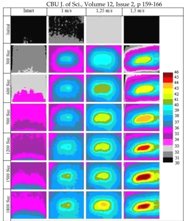
Fig.8 shows the surface temperature variations of pre-viously impacted specimens tested at ±4 mm dis-placement. As seen in this figure, the surface tempera-tures of the specimens increase with time. Specimens impacted at 1 m/s have not showed considerable tem-perature increase. However specimens impacted at 1,25 m/s and 1,5 m/s showed notable temperature increase. On the other hand, the specimens impacted at 1,5 m/s velocity showed the highest temperature increase. Consequently as the impact velocity increas-es the delaminated field increasincreas-es too. Eventually more internal friction occurs and consequently higher temperatures were obtained.
Fig.9 shows the surface temperature variations of pre-viously impacted specimens tested at ±5 mm dis-placement. The obtained temperature variations for ±5 mm displacement and temperature variations for ±4 mm displacement are similar. However, the edge ef-fect becomes important when the end displacement increases. Especially the regions close to clamping are subjected to high stress levels. So, for an intact speci-men, it is expected to observe relatively high tempera-tures near the clamped region as seen in the Fig.9. Fig.10 shows the variation of surface temperatures of specimens subjected to cyclic loading at ±6 mm
dis-CBÜ Fen Bil. Dergi.,Cilt 12, Sayı 2, 159-166 s CBU J. of Sci., Volume 12, Issue 2, p 159-166
164 placement and different impact velocities. This case is similar to the previous cases. In addition, high dis-placement has led to high stress level at the region near clamping and yielded the highest surface tem-perature.
Figure 8. Thermal images of impacted specimens with dif-ferent impact velocities under fatigue loading of ±4mm displacement.
Figure 9. Thermal images of impacted specimens with dif-ferent impact velocities under fatigue loading of ±5mm displacement.
After the test, the test specimens have been checked against damage progression and no considerable ex-pansion of delamination has been observed.
CBÜ Fen Bil. Dergi.,Cilt 12, Sayı 2, 159-166 s CBU J. of Sci., Volume 12, Issue 2, p 159-166
165 Figure 10. Thermal images of impacted specimens with different impact velocities under fatigue loading of ±6mm displacement.
5 Conclusions
In this study, it is shown that the in-situ detection and observation of delamination is possible by the applica-tion of IRT approach under cyclic loading. It is seen that damaged regions create higher heat generation than the other regions. This situation leads to noticea-ble temperature increases at different regions of the specimens’ surfaces. However, the damage can be detected only when it cause considerably temperature increase at the surface of the materials. In this case it is concluded that there must be sufficient frictional heat generation in order to detect the damage. This means that the small damage fields cannot be properly ob-served. On the other hand in order to visualize the damaged field, sufficient cyclic loading level must be applied by means of properly selected end displace-ment.
The selection of the end displacement has big im-portance. In the selection of very small end displace-ment, the damage field cannot be detected because of very low heat generation. However, the applied end displacement must not create damage progression and damage field extension. On the other hand, damage
field must be far enough from clamped regions of the specimens. Otherwise, heat generation can arise near clamped regions and affects the temperature distribu-tion formed by internal fricdistribu-tion of damaged field. This situation can result in misinterpretation. In this case, in order to designate the sufficient end displacement that will not increase the present damage but, will create considerably heat is depending on the stress intensity of the damage field and material's interlami-nar fracture toughness and specimen’s geometry.
6 Acknowledgements
This work was supported by Selcuk University Scien-tific Research Projects Coordinatorship, Konya, Tur-key.
7 References
[1] Luong, M.P. Fatigue Limit Evaluation of Metals Using an Infrared Thermographic Technique. Mechanics of Mate-rials. 1998; 28(1-4), 155–163.
[2] Ball, R.J.; Almond, D.P. The Detection and Measure-ment of Impact Damage in Thick Carbon Fibre Reinforced Laminates by Transient Thermography. NDT&E lnterna-tional. 1998; 31(3), 165-173.
[3] Yang, B.; Liaw, P.K.; Morrison, M.; Liu, C.T.; Buchanan, R.A.; Huang, J.Y.; Kuo, R.C.; Huang, J.G.; Fielden, D.E. Tem-perature Evolution During Fatigue Damage. Intermetallics. 2005; 13(3-4), 419-428.
[4] Kim, B.C.; Kim, Y.H.; Han, J.S. A Low-Cost Thermo-graphic Device for The Detection of Concealed Groove in Metal Plate. Sensors and Actuators A: Physical. 2005; 118(2), 248-253.
[5] Mignogna, R.B.; Jr. Green, R.E. Thermographic investi-gation of High-Power Ultrasonic Heating in Materials. Ul-trasonics. 1981; 19(4), 159–163.
[6] Mignogna, R.B.; Jr. Green, R.E. Changes in Ultrasonic Attenuation, Velocity and Other Parameters Resulting from High-Power Insonation of Metals. In: Proceedings of Ultra-sonics International 1979 Conference. Graz-Austria, 1979, 215–220.
[7] Toubal, L.; Karama, M.; Lorrain, B. Damage Evolution and Infrared Thermography in Woven Composite Lami-nates under Fatigue Loading. International Journal of Fa-tigue. 2006; 28(12), 1867–1872.
[8] Meola, C.; Carlomagno, G.M. Impact Damage in GFRP: New Insights with Infrared Thermography. Composites Part A. 2010; 41, 1839-1847.
[9] Meola, C.; Carlomagno, G.M.; Ricci, F.; Lopresto, V.; Caprino, G. Investigation of Impact Damage in Composites with Infrared Thermography. In: Mazal P, editor. Proceed-ings of 6th NDT in progress. Brno University of Technology. Prague (Czech Republic). 2011; 175-182.
CBÜ Fen Bil. Dergi.,Cilt 12, Sayı 2, 159-166 s CBU J. of Sci., Volume 12, Issue 2, p 159-166
166 [10] Jiang, L.; Wang, H.; Liaw, P.K.; Brooks, C.R.; Klar-strom, D.L. Temperature Evolution During Low-Cycle Fa-tigue of ULTIMET-Alloy: Experiment and Modelling. Me-chanics of Materials. 2004; 36(1-2), 73–84.
[11] Aldave, I.J.; Bosom, P.V.; González, L.V.; De Santiago, I.L.; Vollheim, B.; Krausz, L.; Georges, M. Review of Ther-mal Imaging Systems in Composite Defect Detection. Infra-red Physics & Technology. 2013; 61, 167–175.
[12] Plekhov, O.; Palin-Luc, T.; Saintier, N.; Uvarov, S.; Naimark, O. Fatigue Crack Initiation and Growht in a 35crmo4 Steel Investigated by Infrared Thermography. Fa-tigue and Fracture Engineering Materials and Structures. 2005; 28(1-2), 169-178.
[13] Selek, M.; Sahin, O.S.; Kahramanlı, S. Using Artificial Neural Networks for Real-Time Observation of The Endur-ance State of a Steel Specimen under Loading. Expert Sys-tems with Applications. 2009; 36(4), 7400–7408.
[14] Chrysochoos, A. Infrared Thermography Applied to the Analysis of Material Behavior: a Brief Overview. Quanti-tative Infrared Thermography Journal. 2012; 9(2), 193–208. [15] Usamentiaga, R.; Venegas, P.; Guerediaga, J.; Vega, L.; Lopez, I. Automatic Detection of Impact Damage in Carbon Fiber Composites using Active Thermography. Infrared Physics & Technology. 2013; 58, 36–46.
[16] Usamentiaga, R.; Venegas, P.; Guerediaga, J.; Vega, L.; Lopez, I. Feature Extraction and Analysis for Automatic Characterization of Impact Damage in Carbon Fiber Com-posites using Active Thermography. NDT&E International. 2013; 54, 123–132.
[17] Vavilov, V.P.; Modeling and Characterizing Impact Damage in Carbon Fiber Composites by Thermal-Infrared Non-Destructive Testing. Composites: Part B. 2014; 61, 1–10. [18] Meola, C.; Carlomagno, G.M. Infrared Thermography to Evaluate Impact Damage in Glass-Epoxy with Manufac-turing Defects. International Journal of Impact Engineering. 2014; 67, 1-11.
[19] Lisle, T.; Bouvet, C.; Pastor, M.L.; Margueres, P.; Prieto R. Damage Analysis and Fracture Toughness Evaluation in a Thin Woven Composite Laminate under Static Tension us-ing Infrared Thermography. Composites: Part A. 2013; 53, 75–87.
[20] Yang, B.; Huang, Y.; Cheng, L.; Defect Detection and Evaluation of Ultrasonic Infrared Thermography for Aero-space CFRP Composites. Infrared Physics & Technology. 2013; 60, 166–173.
[21] Harizi, W.; Chaki, S.; Bourse, G.; Ourak, M. Mechanical Damage Assessment of Glass Fiber-Reinforced Polymer Composites using Passive Infrared Thermography. Compo-sites: Part B. 2014; 59, 74–79.
[22] Krishnapillai, M.; Jones, R.; Marshall, I.H.; Bannister, M.; Rajic, N. Thermography as a Tool for Damage Assess-ment. Composite Structures. 2005; 67, 149–155.
[23] Toubal, L.; Karama, M.; Lorrain, B. Damage Evolution and Infrared Thermography in Woven Composite
Lami-nates under Fatigue Loading. International Journal of Fa-tigue. 2006; 28, 1867–1872.
[24] Montesano, J.; Fawaz, Z.; Bougherara, H. Use of Infra-red Thermography to Investigate the Fatigue Behavior of a Carbon Fiber Reinforced Polymer Composite. Composite Structures. 2013; 97, 76–83.
[25] Cura, F.; Curti, G.; Sesanaş R. A New Iteration Method for the Thermographic Determination of Fatigue Limit in Steels. International Journal of Fatigue. 2005; 27(4), 453–459. [26] Curti, G.; La Rosa, G.; Orlando, M.; Risitano, A. Analisi Tramite Infrarosso Termico Della Temperatura Limite in Prove Di Fatica. XIV Convegno Nazionale AIAS, Catania, 1986; 211–220.
[27] Selek, M.; Kahramanlı, S.; Sahin, Ö.S.; Sağlam, H. Thermographical Investigation of Crack Nucleation under Low Cycle Fatigue Loading. Proceedings of the International Conference on Modeling and Simulation. 2006. 28–30 Au-gust. Konya, TURKEY.
[28] Selek, M.; Sahin, O.S.; Kahramanlı, S. Thermographical Investigation of Crack Initiation using Artifical Neural Net-work. 2007. EUROCON – 2007 The International Conference on "Computer as a Tool". Warsaw-Poland, 270-275.
[29] Meneghetti, G. Analysis of the Fatigue Strength of a Stainless Steel Based on the Energy Dissipation. Interna-tional Journal of Fatigue. 2007; 29(1), 81-84.