Copyright © BAJECE ISSN: 2147-284X Abstract—Loss of motor skills in hand due to several reasons
affects daily life in a negative way. Treatment or rehabilitation must be applied in order to reactivate motor skills. Different systems were developed in the rehabilitation process by benefiting from technology. Those systems work as telerehabilitation-based or with external skeleton manipulator. An internet connection is required for telerehabilitation-based systems and a physical therapist must carry out the rehabilitation process for systems with external skeleton manipulator. This shall increase the work load of physical therapist. In this study, it is aimed to decrease the work load of physical therapist and develop a hand rehabilitation system with easier and more flexible usage. With this purpose, a system that consists of three units communicate with each other wirelessly and which could be used even without a physical therapist.
Index Terms—Rehabilitation hand, wireless control, mobile rehabilitation, wearable rehabilitation devices.
I. INTRODUCTION
OSS of motor skills in hand occurs as a result of, hemiplegia, neurotic diseases or muscular diseases. That loss is also a medical problem which affects human life in a negative way. A surgical or medical intervention shall be required. Before or after those interventions, hand rehabilitation shall be applied in order to re-function motor skills that are already lost.
Manuscript received June 5, 2016; accepted September 17, 2016. DOI: 10.17694/bajece.292651
There must be an internet connection where the patient uses the system in order to remote control the system [7]. Systems with external skeleton manipulator could not be used in the hand assessment process since they are designed for forcing the patient to make a certain movement.
In the Wireless Hand Rehabilitation System (WHRS), it is aimed to make the rehabilitation process independent from hospital and physical therapist. Accordingly, rehabilitation process is turned to an autonomous system. Hand figures, which physical therapist could determine and arrange, are included in WHRS. Thus, hand figures for practices could be performed by the system without an internet connection. Physical therapist could make a tailor-made prescription for the patient by changing practice figures as he likes.
Before system shall be used, practice prescription to be used must be loaded to the system by physical therapist. After system is operated, it makes an application report by using the prescription which is determined by physical therapist and the numbers of repetition.
By means of records which is kept during the time when WHRS is used, it is possible to analyze practices of patient and to reform the rehabilitation process due to this analysis. Since units in the system could communicate wirelessly, it provides more flexible usage for the patient. Patient could use WHRS wherever he likes.
II. SPECIFICATIONS OF WHRS
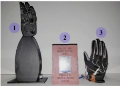
That system actualizes rehabilitation process by simulation. The system consists of a “robot hand” for the patient to see the practice figure, a “data glove” to read data in the figures which are made by patient and a “control center” which ensures all those units work together. While hand rehabilitation firstly, Robot Hand Unit is realized posture/grasp which is planned from physiotherapist then patient try to make this posture/grasp with Data Glove Unit. All data from glove hand unit is recorded by control center unit. Those units communicate with each other wirelessly. XBee S2 RF module is used in order to allow units to communicate wirelessly with each other [8]. Units in the system are all shown in Fig.1.
Fig. 1 Wireless hand rehabilitation system. (1) robot hand unit, (2) control center unit, (3) data glove unit
Wireless Hand Rehabilitation System (WHRS)
A.Gücüyener, and E. Kaplanoğlu
L
Hand rehabilitation is a process which includes assessment and rehabilitation of hand. Traditional methods could be used during the assessment process. But, for the rehabilitation process, several rehabilitation systems are developed as an alternative for traditional methods.
When those rehabilitation systems that could be used in hospitals or physical therapy centers are reviewed; it is seen that systems that shall decrease the work load of physical therapist [1, 2] or that shall increase the participation of the patient to the rehabilitation process [3, 4] are developed. It could be said that those systems are with external skeleton manipulator [5] or tele-rehabilitation based [6]. Those systems, which are developed in order to decrease work load of physical therapist, are generally operated remote-controlled based [7].
A. GÜCÜYENER, Department of Electronic Technology, Vocational
School, Istanbul Arel University, Istanbul, Turkey, (e-mail:
E. KAPLANOĞLU, Department of Mechatronics Engineering, Technology
Faculty, University of Marmara, Istanbul, Turkey, (e-mail:
A. Data Glove Unit
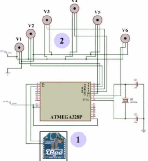
Data Glove Unit consists of a glove, 6 pieces of flex sensors [9, 10], a control card with ATmega328P microcontroller [11] and XBee S2 RF wireless module [8]. A system with microcontroller is formed for flex sensors and wireless communication module in Data Glove in order to work together. Wiring diagram of microcontroller with other units is shown in Fig.2. The unit must send practice information of the patient to the Control Center.
Fig. 2 Data glove unit connections. (1) rf module, (2) flex sensors
Values shown in Table 1 are measured by flex sensors in Data Glove.
TABLE I FLEX SENSOR'S VALUE
Analog
Read In_min In_max Out_min Out_max FS1 (A0) 515 600 5 175 FS2 (A1) 665 680 5 175 FS3 (A2) 290 500 5 175 FS4 (A3) 335 520 5 175 FS5 (A4) 315 510 5 175 FS6 (A5) 270 460 5 175 Map Function = (FS(x)-In_min) *(Out_max-Out_min) /
(In_max- In_min) + Out_min
Flex sensor values in Table 1 are turned to motor angle values by using map function [12] in Eq. (1).
(1)
B. Robot Hand Unit
The unit consists of a prototype hand that is made by printing from a 3-D printer, 6 pieces of servo motor in order to apply finger angles to that hand [13], XBee S2 RF module [8] for wireless communication and ATmega328P microcontroller [11] which shall control the unit itself.
In the robot hand, which consists of 17 parts in total, joints are made of springs that are hanged by pins. After joints are completed, nylon thread connected to 6 servo motors goes
provide flexion and extension for fingers. Servo motors and wireless communication module that are used in Robot Hand unit are controlled by a system with microcontroller. The connection of this microcontroller with other units is shown in Fig.3.
V1 thumb is used in order to provide abduction and abduction movement. Servo motors named V2-V6 provide flexion and extension movement for relatively thumb, fore finger, middle finger, ring finger and little finger. While flexion is provided by servo motors in all fingers, extension movements of fingers are supported with springs.
Fig. 3 Robot hand unit connections. (1) rf module, (2) servo motors
C. Control Center Unit
This unit consists of a touchscreen [14], real-time time module [15], XBee S2 RF [8] module and wireless SD extension port [16] and an ATmega2560 [17] microcontroller in order to control the unit. Microcontroller communicates with touchscreen via a serial port. System is controlled in line with messages coming from touchscreen. Content and repetition information in the memory card are read by the microcontroller and an application table shall be made. Wiring diagram of the unit is shown in Fig.4.
Fig. 4 Control center unit connections. (1) real time clock module, (2) rf module, (3) memory card module, (4) touch screen.
Copyright © BAJECE ISSN: 2147-284X http://www.bajece.com
D. Wireless Network
In that system, XBee S2 RF modules in Data Glove and Robot Hand Units are configured as director. They are also configured as coordinator in Control Center unit. Those three modules are examined and tested by connecting to a computer without integrating the network that they form. Identity called “2015” is determined as PAN ID. Physical address of the coordinator is recorded in the directors and the network is formed in Fig.5 where they could communicate with each other. Message no.1 in Fig.5 is used to control the communication. Control Center unit sends “CR!” and “CG!” messages to the network. When message “OKR!” from Robot Hand Unit and message “OKG!” from Data Glove Unit are receives, it is understood that there is no problem in the communication. Message no.2 in Fig.5 states messages between Control Center and Robot Hand. Control Center sends a new figure to Robot Hand. Robot Hand performs that figure and send “OKR!” message. Message no.3 in Fig.5 states messages between Control Center and Data Glove. Control Center sends “DG!” message. Data Glove sends the data obtained by measuring the value starting with “DGE!” from flex sensors in the map function to Control Center Unit.
Fig. 5. Structure of the wireless network (1) communication control of WHRS (2) control center unit communication with the robot hand unit (3) control
center unit communication with the data glove unit
III. SOFTWARE ARCHITECTURE OF WHRS
Generally, the operating logic of the system is to include the prescription to be applied with a memory card stick in the Control Center in the system itself. Due to touchscreen in Control Unit, tolerance and time values could be determined by user with the help of menus with Turkish and English language options. After practice information in the memory card shall be sent to the Robot Hand Unit, Robot Hand unit performs this practice. Patient who shall use the system shall also wear that glove on his hand and tries to do the same practice. At the same time, there shall be some visual messages giving information to the user are shown on the screen. Residual time and instant finger angles are shown on the screen. While system is being operated, finger angle information from Robot Hand and Data Glove shall be compared and results shall be recorded to the memory card in
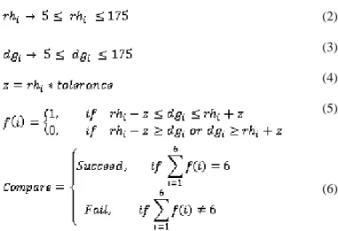
the Control Center. Mathematical transactions in Eq. (5) and (6) shall be used in that comparison transaction.
(2)
(3)
(4)
(5)
(6)
If the user could complete the practice successfully, then that information shall be recorded as successful in the memory card. If user could not perform the practice within the time range, then system shall record this as an unsuccessful attempt and pass to the other practice. Software algorithm of WHRS is shown in Fig.6.
Fig. 6. System algorithm
IV. CASE STUDIES
When WHRS is operated, first the name of the application shall be formed in Robot Hand Unit and that shall be compared with values from Data Glove unit. Both successful
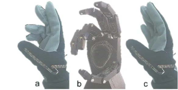
and unsuccessful record examples are shown in Fig.7 for an example figure.
Fig. 7 Case Study (a) succeed figure (b) original figure (c) fail figure In Fig.7, two example studies are taken into consideration for the same figure. In the Example A, since all fingers are within the tolerance range, it shall be deemed successful. In Example B, since 5th and 6th values are out of the tolerance range, this shall be recorded as unsuccessful/failed study. Those values are shown graphically in Fig.8.
Application values at the moment when system is being used shall be kept and recorded in a file called “results.csv” in the memory card. As you could see in Table 2, number of steps, date, time, tolerance and arranged time information in the application table of the system are added to “results.csv” file. RH1 and DG1 values are parts where related data of Robot Hand Unit and Data Glove are compared with each other. It is deemed that the value from Robot Hand Unit has a surplus of missing in the amount of tolerance value.
After all practices are completed, user shall give the memory card which includes all details about practices to the physical therapist. Physical therapist could see all details that which practices could be made by user or not with the information on time and date. If physical therapist finds necessary, he could update the system by removing those practices which are already done and by adding new practices. Physical therapist could apply different practices to different patients with the same system.
TABLE II
THE RESULTS AFTER USING THE SYSTEM
Step Date Time Tolerance SetTime Sec RH1 DG1 RH2 DG2 RH3 DG3 RH4 DG4 RH5 DG5 RH6 DG6 Result
1 15.12.2015 15:40 30 60 54 40 39 175 175 175 175 175 175 175 175 175 175 Succeed 2 15.12.2015 15:42 30 60 0 50 45 10 175 10 28 10 18 10 21 10 24 Fail 3 15.12.2015 15:52 30 60 29 40 31 175 175 175 163 175 175 175 166 175 175 Succeed 4 15.12.2015 16:00 30 60 39 120 136 100 90 12 15 12 14 80 72 80 70 Succeed
Fig. 8 case study of the comparison operation (a) succeed figure (b) fail figure
V. CONCLUSIONS
In this study, a system which operates hand rehabilitation procedure autonomously and independent from physical therapy center and physical therapists. Due to this system, patient could use hand rehabilitation process wherever he likes without any need for internet connection. Also, those units which communicate wirelessly with each other provide flexible usage.
VI. FUTURE WORK
System is made for only right hand. A Data Glove for left hand shall be made and this new glove shall be used in a rehabilitation center and results shall be reviewed.
It is considered to add multi-user function to the system by applying the system to more than one patient who have same diseases.
REFERENCES
[1] Zhang, S., Guo, S., Gao, B., Hirata, H., Ishihara, H.,(2015), “Design of a novel telerehabilitation system with a force-sensing mechanism.”, Sensors, Vol.15, pp. 11511-11527, ISSN: 14248220, (Switzerland). [2] Durfee, K. W., Weinstein, A. S., Carey, R. J., (2005), “Home stroke
telerehabilitation system to train recovery of hand function”, 9th International Conference on Rehabilitation Robotics, pp.353-356 [3] Pyk, P., Wille, D., Chevrier, E., (2008), “A Paediatric Interactive
Therapy System for Arm and Hand Rehabilitation”, IEEE Journal Virtual Rehabilitation. pp. 127-132.
[4] Sha, M., Varley, R. M., Richards, J., (2009), “Overcoming the information overload problem in a multiform feedback based virtual reality system for hand motion rehabilitation”, International Conference on CyberWorlds., pp 51–56.
[5] Leonardis, D., Barsotti, M., Loconsole, C., Solazzi, M., Troncossi, M., Mazzotti, C. & Frisoli, A. (2015), “An EMG-controlled robotic hand exoskeleton for bilateral rehabilitation”, Vol.8, No.2, pp.140 – 151. [6] Heuser, A.; Kourtev, H.; Winter, S.; Fensterheim, D.; Burdea, G.;
Hentz, V.; Forducey, P., (2007), “Telerehabilitation Using the Rutgers Master II Glove Following Carpal Tunnel Release Surgery: Proof-of-Concept”, Neural Systems and Rehabilitation Engineering, IEEE Transactions, Vol.15, pp. 43 – 49.
[7] Cortese, M.; Cempini, M.; de Almeida Ribeiro, P.R.; Soekadar, S.R.; Carrozza, M.C.; Vitiello, N.A.,(2015), “Mechatronic System for Robot-Mediated Hand Telerehabilitation”, Mechatronics, IEEE/ASME Transactions, Vol.20, pp.1753 – 1764 .
[8] XBee ZigBee http://www.digi.com/products/xbee-rf-solutions /modules /xbee-zigbee, Access Date: 01.04.2015.
[9] 2.2 inch Flex Sensor https://www.sparkfun.com /products /10264 Access Date: 15.04.2015.
Copyright © BAJECE ISSN: 2147-284X http://www.bajece.com [11] Arduino Uno, https://www.arduino.cc /en /Main /ArduinoBoardUno,
Access Date: 20.04.2015.
[12] Map Function, https://www.arduino.cc /en /Reference /Map, Access Date: 23.04.2015.
[13] SG 5010 servo motors, http://www.towerpro.com.tw /product /sg5010-4/, Access Date: 20.04.2015.
[14] uLCD-32PTU touch screen, http://www.4dsystems.com.au/product /uLCD _32PTU / Access Date: 01.11.2015.
[15] DS1302 RTC datasheet, http://datasheets.maximintegrated.com /en /ds /DS1302.pdf, Access Date: 01.11.2015.
[16] Wireless SD Shield, https://www.arduino.cc /en /Main /Arduino Wireless Shield, Access Date: 12.04.2015.
[17] Arduino Mega 2560, https://www.arduino.cc /en /Main /arduino Board Mega 2560, Access Date: 12.04.2015.
BIOGRAPHIES
Aytek GÜCÜYENER was born in Istanbul, Turkey in
1982. He received the B.Sc. degrees in Electronic and Computer Education from Faculty of Technical Education, Sakarya University, in 2006. 2006 to 2011, he was a lecturer at the Istanbul Aydın University. Since 2011, he has been working as an instructor at the Arel University Vocational School Electronics Technology Program. His research areas include microcontroller systems, embedded systems, communication systems and networked control systems.
Erkan KAPLANOĞLU received the bachelor's degree
from Marmara University Electric Department, in 1996. He completed his M.Sc. and Ph.D. thesis at Computer-Control Department of Marmara University, Institute for Graduate Studies in Pure and Applied Sciences, in 2000 and 2006, respectively. In March 2014, Dr. Kaplanoğlu became Associate Professor at Marmara University, Mechatronics Department. He has been awarded YGGDRASIL Award (Young Guest Doctoral Researchers in Norway) in 2010. He worked as research assistant professor at Department of Mechanical Eng. Vanderbilt University Faculty of Engineering Nashville/TN, USA from 2011 to 2012. His research areas are Biomechatronics systems, Lower limb Prosthesis, modeling, identification and control. Multivariable, Model Predictive Control, Data Acquisition Systems (DAQ).