INTEGRAL EQUATION BASED METHOD FOR
THE
FAST
ANALYSIS OF IRREGULARLY CONTOURED LARGE
FINITE PHASED ARRAYS
Vakur B.
Ertiirk*,
Ozlem Aydin
(ivit
*Dept.of Electrical and Electronics Engineering, Bilkent University, Ankara, Turkey e-mail: [email protected]
tDept.
of Electrical and ElectronicsEngineering,
MiddleEastTechnicalUniversity, Ankara,
Turkey
e-mail: [email protected]Keywords: Finite arrays; Method of Moments; Generalized Forward Backward Method.
Abstract
A fast and accurate integral equation based hybrid method that can investigate electrically large, arbitrarily contoured finite planar arrays of printed elements is developed. The method is a hybridization of the Galerkin type Method of Moments (MoM) and Generalized Forward Backward Method (GFBM) with the grounded dielectric slab's Green's
function;
and the acceleration of the resultanthybridmethodby a discrete Fourier transform (DFT) based acceleration
algorithm. Numerical results in the form of array current
distribution are given for arbitrarily contoured as well as
thinned arrays ofprobefedmicrostrip patcheswhere current on each element expanded by more than one subsectional basis function.
1
Introduction
Phased arrays ofprinted microstrip patches are vital in many commercial andmilitary applications. Hence, their efficient andaccurateanalysis becomes crucial in ordertoobtain such
arrays with better performance metrics. Unfortunately, majority of the developed analysis methods and available Computer AidedDesign (CAD) toolsare either slowor lack ofrigor when they are used for the investigation ofphased
arrays ofprinted elements on grounded dielectric slabs in
particular for the electrically large but finite and irregularly
contoured ones. Moreover, if array thinning is required (so
that theperiodicity is deteriorated), solution process with the
available tools becomesmoredemanding intermsofstorage andcomputingtimerequirements.
Inthisstudy,weproposeafast andaccurateintegral equation
based hybrid method that can investigate electrically large, arbitrarily contoured finiteplanararrays ofprinted elements,
which canbe arbitrarily shaped probe-fed patchesaswell as
printed dipoles [2]. The method is a hybridization of the Galerkin type Method ofMoments (MoM) and Generalized Forward Backward Method (GFBM) [10] with the grounded
dielectric slab's Green'sfunction; and the acceleration of the resultant hybrid method by a discrete Fourier transform
(DFT) based acceleration algorithm [5]. The method also uses the "virtual element" concept [7] with "sub-arraying"sothat arrays with irregular boundaries as well as sparse and
non-periodic arrays produced by array thinning process can be investigated without a major difficulty.
The solution process starts by introducing the virtual elements. Thus, regardless of the array shape, the array is extended to a two dimensionally periodic rectangular array. Then, an integral equation (IE) that uses the grounded dielectric slab's Green's function as its kernel is formed including the virtual elements and is solved with a combination of Galerkin type MoM and GFBM. Briefly,
unknown current coefficients corresponding to a single
element are initially solved by MoM. The solution for the unknown entire array current coefficients is then obtained
through GFBM. Because the time-consuming matrix-vector products during the forward and backward sweeps of GFBM
are the main bottle neck of the solution procedure, it is acceleratedusing a DFTbased acceleration algorithm,which divides the array into strong and weakregions. However, as
the complicated array elements have more than one basis functions perelement, the available DFTbased acceleration
algorithm should be generalized. Hence, with the aid of the virtualelements, periodic sub-arraysareproducedasmanyas
the number of basis functions per element so that for each
sub-array, one can usethe available DFT based acceleration
algorithm. The final result is the superposition of the
sub-arrayresults.
It is worthwhile to mention at this point that effects of the virtual elements should be shed from the final solutionasthey
areaddedtothe actual arraytomaximize theefficiency of the
solutionprocedure andtominimize the storagerequirements
of the method. Therefore, specialconditions are imposedon
them particularly during the strong region evaluations as
explainedinthe subsection 2.3.
Numerical results are provided for various irregularly
contoured as well as thinned arrays using the proposed
method and are comparedwith the results ofaconventional
hybridMoM/Green'sfunction methodto assessthe accuracy andefficiencyof theproposed method. Moreexamples will beprovided duringthepresentation.
2 Formulation
In this section, the formulation of the proposed method together with its salient features is provided starting by depicting a generic geometry of an irregularly contoured phased array. Then, we briefly discuss how GFBM is used to solve the MoM matrix equation obtained from the electric fieldintegral equation (EFIE) that uses the Green's function for the grounded dielectric slab. Finally, implementation of the DFT based acceleration algorithm for irregularly contoured arrays ispresented together with a discussion of the imposed conditions on virtual elements.
2.1 Geometry
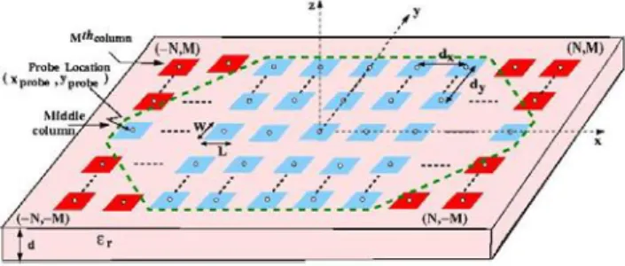
Figure 1 illustrates a finite, arbitrarily contoured planar array ofmicrostrip patches. The microstrip patches areprintedon
the dielectric-air interface(z=O)ofagroundeddielectric slab with athickness d and arelative dielectric constant
6r.
Eachpatchis assumedtobeprobe-fedwithanideal current source
(Xprobe,Yprobe),
has a length L, width W. In Figure 1, actual elements of the array are depicted with blue (light-coloured for black and white illustrations) andtheyremain inside the dashed line that denotes the array boundary. Microstrip patchesthat lie outside the array boundaryaredenotedbyred(dark-coloured) and they form the virtual elements. By including the virtual elements, a finite, periodic, rectangular
array is obtained. In a similar fashion in the case of thinned
arrays,the actual array maynotbeperiodic. However, again by addingthe virtual elements the thinnedarrayis completed
to afinite periodic rectangulararray. Consequently, the final
array (after the inclusion of virtual elements) to be solved with theproposedmethod is always afinite, periodic, planar
arrayof(2N+l)x(2M+1) identicalmicrostrip patchesthatare
uniformly spacedfrom theirneighbours bydistances
dx
anddy
inthe x and y directions, respectively.Figure 1.Geometryofaplanar, irregularlycontouredarrayof
probe-fed microstrip patches.
2.2 Method of Moments Formulation and the Generalized Forward Backward Method Solution for PhasedArrays Using anEFIE, whose kernel is thegrounded dielectric slab
Green's function [1], [3,4], [9], expanding the unknown induced array surface current in terms of a finite set of
piecewise sinusoidal basis functions, and using a Galerkin
procedure,amatrix-equationinthe form of
is formed. In (1), I=
[A,mr
] is the unknown column vector ofcurrentcoefficients
Anmr
that represents the rth basis function belonging to the nmith patch, and Z=[Znmrpqs
]
is theimpedance matrix of the array with entries
Znmr,pqs
each of which denotes the mutual impedance between the rth basis function of thenmithpatch andsthtesting function of thepqth
patch. Finally, V=lVpqs
] at the right hand side of (1)represents the known voltage vector responsible from the excitation of the array. Explicit expressions for
Znmr,pqs
andVpqs
canbe found in[1,2].
To solve (1) for the unknown current amplitudes,
Anmr,
GFBM is used. Briefly, the current vectorI is decomposed into its forward,If
, and backward, Ib, components.Similarly,the impedance matrixZis decomposed into three matrices, namely, Zsg formed by the block diagonal matrices ofZcorresponding to the impedance matrix of a single patch, and Z fg and Zbg formed by the lower and upper triangular parts of Z, respectively, with Zsg is subtracted. Then, the
original matrix-equationgivenby (1)isexpressedas
ZsgJf
=
-Zfg (IJf
+Ib)
(2)
Zsgjf
=_Zbg(I
f +Zb)
(3)Initializing
Ib
to zero atthe first iteration, (2) is solved forIf,
and the resultantIf
is used in (3) solve for Ib. To obtain the final converged result for the unknown currentcoefficients usually requires four or five iterations.
Consideringthe fact that the total number of unknowns in(1)
is
Ntot,
which is equal to the total number of antennas in the array multiplied by the total number of basis functions for each element, the computational complexity as well as the storage requirement of GFBM areO(N20t
) due to the repeated and time-consuming computations ofZfgI
andZbgI
in (2) and (3), respectively. Therefore, solving very large arrays using GFBM may not be feasible. However, with theDFTbased acceleration algorithm proposedin [2],which is thegeneralized form of thealgorithm explained in [5] and used in [6,7,8], both the computational complexity and the storage requirements of the method reduces toO(Ntot),
which makes the methodpromising whendealing with very
large arrays.Abriefdescription of the methodtogetherwith its salient features isprovidedinthefollowingsubsection. 2.3DFTBasedAccelerationAlgorithm
For finite arrays, array current distribution is not uniform
along the array and significant variations can be observed
nearthe feed locations and atthe array boundaries as shown in Figure 2(a), for a l9xl9 element rectangular, probe-fed microstrip patch array (array and substrate parameters are
given in the caption of the figure), and in Figure 3(a) for a
1501 element octagonal, probe-fed microstrip patch array
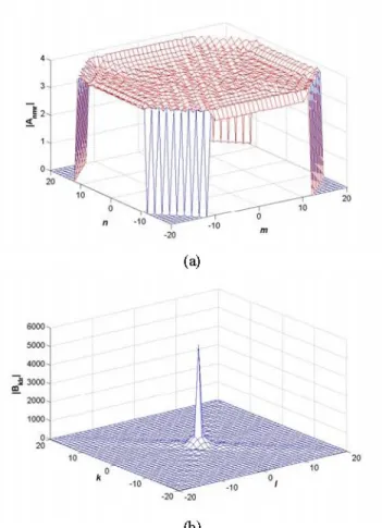
(again array and substrate parameters are given in the caption of the figure). Furthermore, shape of the array boundary may also affect this current distribution as can be seen from the comparison of Figure 2(a) with Figure 3(a). However, the DFT spectrum of finite arrays are very compact as seen both in Figure 2(b) and Figure 3(b) regardless of how these arrays arecontoured as long as they are relatively large. Therefore, working with the DFT spectrum of the array currents and selecting only the significantDFTtermsusually provide very accurateresults. The mostimportantDFTtermis the middle one (see both Figure 2(b) and Figure 3(b)), that corresponds totheDFT spectrumof an infinite array. Selecting thisDFT
term is a necessary condition and usually yields sufficient accuracy for many engineering applications. However, if more accuracyis desired, a few DFT terms around the middle DFTterm canbe taken.
(a) 1XO 77iwo~~~~~~~~~~~~~~~~~~~~~~~~ 200 0 0~~~~~~~~~~~~~~~~ (b)
Figure2. (a)Currentamplitudesand(b)DFTspectrumof
currentsof 19x19elementrectangular probe-fed
microstrip patcharray.Arrayparametersare:d =0.04%,,
= 2:55,L =W 0.3 d= dy .5,Xprobe = -L2,
Yprobe =0.Three ~-directed basis functionsareused for eachpatch.
Figure 3. (a) Current amplitudes and (b)DFTspectrumof currentsof 1501 elementoctagonal probe-fed microstrip
patcharray.Arrayparametersare:d=0.04X0, gr= 2:55, L=W=0.3X0 dx=
dy=
0.5X0,Xprobe=-L/2,yprobe=0.Three x -directed basis functionsareused for each patch.
The DFT based acceleration algorithm is based on this
compactnessof the DFT spectrum andverywell suited for the
fast andaccuratesolution ofrectangulararrays.Therefore, as
the first step of this algorithm, the array under study is
mathematically extendedtoarectangulararrayby introducing
virtual elements. In thecase ofanirregularly contouredarray,
like theone depicted in Figure 1,virtual elements are added
outside theboundarytomake itarectangularone.Inthecase
ofathinnedarray,the arrayboundary mightbearectangular
boundary. However, periodicity of the array might be
distorted.Then,virtual elements mustbe addedtomake ita
periodic array. As a result, the first step is to obtain a
rectangular, periodicarrayof identical elements. Then, inside
the GFBM, for both forward and backwardsweeps, the DFT
based accelerationalgorithm ([2], [5,8])startsby dividingthe
contributing elements (elements that are in the front ofa
receiving element) into strong and weak interaction groups
such that
ZfgI
= E AnmrZnmr,pqs +AnmrZnmr,pqs
(4)n,m,rEstrong n,m,rEweak
(a)
where strong and weak groups are denoted by strong and weak, respectively. The number of elements that form the strong group is fixed and very small compared to the entire array, but contributions coming from this group assure the fundamental accuracy of the overall solution. Thus, strong group contributions are obtained in an element-by-element fashion with the GFBM [2]. As mentionedabove, inclusion of virtual elements helps us to obtain aperiodic array froman
irregularly contouredand/or from a thinned array so that both thecomputingtime and storage requirements areminimized. However, effects of them should be shed from the final solution. Thus, in the computation of strong region contributions, voltagesonthese elements are set to zero(i.e.,
Vpqs
=0 if pq E virtual elements) and mutual couplings relatedtothese elements are set to zero (i.e.,Znmr,pqs
=0 ifnm and/or pq E virtualelements).
On the other hand, computation of the weak region
contributionsusingGFBMwithoutanacceleration algorithm
constitutes the main bottleneck of the solution. However, these weak region contributions only provide minor corrections tothe strong regioncontributions. Therefore, the
DFT spectrum of the array current distribution is used in
computing the weak region contributions by selecting only
the significantDFTterms. Itshould bekeptinmind that the current distribution on each element (probe-fed microstrip patch)isexpanded usinganarbitrarynumber of subsectional (piecewise sinusoidals) basis functions. Hence, the acceleration algorithm presented in [5] and used in [6,8] is modified based on the two facts: (i) array elements are identical (i.e., each element is represented using the same
number of basis functions), (ii) array is periodic. Briefly in the modified accelerationalgorithmwefirst consideronlythe first basis function of each element and form a periodic
subarray of elements represented by a single basis function.
Then, the DFT acceleration algorithm used in [6,8] is
implemented. The same procedure is repeated for all other basis functions and allDFTcontributionsaresuperposed bya
summation over the number of basis functions for a single patch Nb. As a result, the weak region contributions are
represented bythegeneric equation given by
Nb
[ZIp]pqs;weak
E E BklrCklr,pqs
(5)r=1 -klcQ
where Q denotes the number of selectedDFTterms, Bklr is the
kith
DFT term of the subarray formed by therth
basisfunctions,and kn Im jCnjv8y,,ndy
j2N+1
-2M+1Cklr,pqs
-Znmr,
pqse
e e e n,meweak (6)representsthe contribution of the
kith
DFTtermof therth
basis functiontothe5thbasis function of thepqth
receivingelement.Efficient evaluation of (6) is crucial for the efficiency of the method. Hence, (6) is computed in an iterative way as explained in [2].
Onefinal remark is again howto shed the effects of virtual elements from the solution. As opposed to the strong region computations, during the computation of weak region
contributions, all mutualcouplingcalculations are performed
asifthere isnovirtual element in the entire array. The main reason is that in the computation of DFT coefficients
(i.e.,
Bklr
),
A,nmr
values for virtual elements are zero. So, if allDFT terms are employed, utilization of nonzero coupling when a virtual element is involved does not affect the accuracy. In reality, we are using only a few (sometimes single) DFT terms that canyield a smallerror. Fortunately,
such an error does not affect the overall accuracy of the solution.
Beforeproviding the numerical results it should be mentioned that with theDFTbased accelerationalgorithm, theproposed
method has an
O(Ntot)
computational cost and storage requirements since both the number of significantDFTterms, Q,and the size of the strongregionare smallcomparedtothe total number of unknowns andtheyarefixedregardlessof the size andshapeof the array.3 Numerical Results and Discussion
Numerical results in the form of array current distribution
pertaining tovarious electrically large, irregularly contoured
or thinned two-dimensional finite arrays of probe-fed
microstrip patches on grounded dielectric slabs are givento assesstheefficiencyand accuracy of theproposedmethod. The first numerical example is a finite array having an
octagonal array boundarywhich contains 1501patches.When the array is extended to a rectangular array by adding the virtualelements,the final arraytobe solvedbytheproposed
method becomes a 41x41 array. All the patch, array and substrate related details are given inthe captionofFigure 4, which shows the comparison for the magnitude of the array
current coefficients,
IAnmr
obtained with the proposed method, namely, DFT-GFBM and with the conventionalhybridMoM/Green'sfunctiontechniquefor the
5th
column inFigure 4(a) and for the middle column inFigure 4(b). Useof 3 DFT terms with a 3x3 strong region yields an error of approximately4.5%for the arraycurrents.
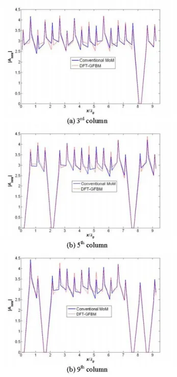
Thenext examplecorresponds to athinned array. This array is obtainedby randomly throwingaway 10%of the elements of a rectangular l9xl9 array. Therefore, when the virtual elementsare included,the original l9xl9rectangulararrayis obtained. Similar to the previous example, Figure 5 shows the comparison of
IAnmr
obtained with the DFT-GFBM and with the conventional hybrid MoM/Green's functionFigure 5(b) and Figure 5(c), respectively. Using a 3x3 strong region with 3 DFT terms yields an error of 5.7 % for the DFT-GFBMresults. ICmnentinMl Mk (a) DcGFuM XIA.
(a) 3rd
column (a)5th column CovninlM6A DF~F BM x5tl(b)
5th
column (b)Middle columnFigure 4. Comparison of the magnitude of the induced current
IAnmrI
obtained via GFBM/Green's Function-DFT and the conventional MoM/Green's function methods for 1501 elementoctagonal probe-fed microstrip patcharray.Arrayparametersare: d= 0.04X0,
g,=
2:55,L=W=0.3X0d,=
dy= 0.5%0,
Xprobe -L/2; yprobe 0.Three x-directed basis functionsareused for eachpatch.As seeninall numerical examples providedinthispaper,the
agreement between the reference solution and the DFT-GFBM solution isfairly good. Accuracy of the solutions can
be increased in the expense of increasing the size of the
strongregion (thoughwe donotrecommend ittoomuch) or
by slightly increasingthe number of DFTtermswhichmight
beacceptablefor certainapplications.More numericalresults, particularly for thinned arrays, will be provided during the
presentation.
(b)9thcolumn
Figure5.Comparisonof themagnitudeof the inducedcurrent
IAnmr
obtained via GFBM/Green's Function-DFT and theconventional MoM/Green's function methods for 10%
randomlythinned19xl9elementprobe-fedmicrostrip patcharray.Array parametersare:d=
0.04%o,
g,=
2:55, L=W=0.3%0
dx=dy=
0.5X0, Xprobe= -L/2; yprobe= 0.Threex-directed basis functionsareused for eachpatch.
4
Conclusions
A novel method that can investigate electrically large, arbitrarily contoured and/or thinned finite planar arrays of printed elements with storage and central processing unit (CPU) requirements of
O(Ntot)
is developed. With the virtual-element concept, both arbitrarily contoured and/or thinned arrays are first completedto afullrectangular array, where the array elements are identical and the array is periodic. Then a hybrid combination of the Galerkin type MoMand GFBM with the grounded dielectric slab's Green's function is developed and accelerated by a DFT based accelerationalgorithm. Numerical results in the form of arraycurrentdistribution obtained with theproposedmethod agree well with the solutions obtained via conventional methods.
Acknowledgements
This project is supported in part by the Turkish Scientific and technical Research Council (TUBITAK) under the Grants
EEAG-104E044and TurkishAcademy of Sciences (TUBA)-GEBIP.
References
[1] 0. Bakir. "Investigation of finite phased arrays of printed antennas on planar and cylindrical grounded dielectric slabs", M.Sc. thesis, Bilkent UniversityDept. of Electrical and ElectronicsEngineering, (2006).
dipole arrays", Microwave and Optical Technology Letters, 37, pp. 20-26,(2003).
[7] 0. A. C,ivi, V. B. Erttirk, H.-T. Chou. "Extension of forward-backward method with DFT-based acceleration algorithm for the efficient analysis of large periodic arrays with arbitrary boundaries", Microwave and Optical Technology Letters, 47, pp. 293-298, (2005). [8] V. B. Erttirk, H.-T. Chou. "Efficient analysis of large
phased arrays using iterative MoM with DFT-based acceleration algorithm", Microwave and Optical Technology Letters, 39, pp. 89-94, (2003).
[9] M.Marin, S.Barkeshli, P. H. Pathak. "Efficient analysis of planar microstrip geometries using a closed-form
asymptotic representationof thegroundeddielectric slab Green'sfunction",IEEETrans.Antennas Propagat., 37, pp.669-679,(1989).
[10] M.Pino, L. Landesa, J. L. Rodriguez, F. Obelliero, R. J. Burkholder. "The generalized forward-backward method for analyzing the scattering from targets on ocean-like rough surfaces", IEEE Trans. Antennas Propagat., 47, pp.961-968,(1999).
[2] 0. Bakir,
0.
A. C,ivi, V. B. Erttirk, H.-T. Chou. "Efficient analysis of phased arrays of microstrip patches using a hybrid generalized forward backward method/Green's function technique with a DFT based acceleration algorithm", submitted to IEEE Trans. Antennas Propagat.[3] S. Barkeshli. "An efficient approach for evaluating the
planar microstrip Green's function and its applications
totheanalysis ofmicrostrip antennasand arrays", Ph.D.
dissertation, The Ohio-State University Dept. of ElectricalEngineering, (1988).
[4] S. Barkeshli, P. H. Pathak, M. Marin. "An asymptotic
closed-form microstrip surface Green's function for the efficientmomentmethodanalysis of mutualcouplingin
microstrip antennas",IEEE Trans. AntennasPropagat.,
38,pp. 1374-1383,(1989).
[5] H.-C. Chou, H.-K. Ho. "Implementation ofa forward-backward procedure for the fast analysis of
electromagnetic radiation/scattering from two
dimensional large phased-arrays", IEEE Trans.
AntennasPropagat., 52, pp. 388-396,(2004).
[6]