i
ORGANICALLY MODIFIED SILICA
NANOSTRUCTURES BASED FUNCTIONAL
COATINGS FOR PRACTICAL APPLICATIONS
A THESIS SUBMITTED TO
OF THE GRADUATE SCHOOL OF ENGINEERING AND SCIENCE OF BILKENT UNIVERSITY
IN PARTIAL FULFILLMENT OF THE REQUIREMENTS FOR THE DEGREE OF
MASTER OF SCIENCE IN
MATERIALS SCIENCE AND NANOTECHNOLOGY
By
Urandelger Tuvshindorj
August, 2015
ii
ORGANICALLY MODIFIED SILICA NANOSTRUCTURES BASED FUNCTIONAL COATINGS FOR PRACTICAL APPLICATIONS By Urandelger Tuvshindorj
August, 2015
We certify that we have read this thesis and that in our opinion it is fully adequate, in scope and in quality, as a thesis of the degree of Master of Science.
Prof. Dr. Mehmet Bayındır (Advisor)
Assoc. Prof. Dr. Hatice Duran
Assist. Prof. Dr. H. Tarik Baytekin
Approved for the Graduate School of Engineering and Science:
Prof. Dr. Levent Onural Director of the Graduate School
iii
ABSTRACT
ORGANICALLY MODIFIED SILICA NANOSTRUCTURES BASED
FUNCTIONAL COATINGS FOR PRACTICAL APPLICATIONS
Urandelger Tuvshindorj
M.S. in Materials Science and Nanotechnology Supervisor: Prof. Dr. Mehmet Bayındır
August, 2015
In the past decades, the fabrication of superhydrophobic surfaces have received considerable attention due to the variety of potential applications ranging from biology to industry. Although significant progress has been made in their fabrication and design, there is still need to solve some problems in real-life use of these coatings, such as low stability against external pressure, lack of long term robustness, challenges in presice control over the degree of wettability and the need for facile fabrication methods. In this context, this thesis seeks simple solutions for mentioned problems based on organically modified silica superhyrophobic coatings.
First, we investigate the stability of the Cassie state of wetting in transparent superhydrophobic coatings by comparing a single-layer micro-porous coating with a double-layer micro/nanoporous coating. The stability of the Cassie state in coatings were investigated with droplet compression and evaporation experiments, where external pressures as high as a few thousand Pa are generated at the interface. A droplet on a microporous coating gradually transformed to the Wenzel state with increasing pressure. The resistance of the micro/nano-porous surfaces against Wenzel transition during the experiments were higher than microporous single-layer coating and even higher than leaves of Lotus; prevalent natural superhydrophobic surface. Then, we reported a facile method for the preparation hydrophilic patterns on the superhydrophobic ormosil surfaces. On the defined areas of the superhydrophobic ormosil coatings, wetted micropatterns were produced using Ultraviolet/Ozone
iv
(UV/O) treatment which modifies the surface chemistry from hydrophobic to hydrophilic without changing the surface morphology. The degree of wettability of the patterns can be precisely controlled depending on the UV/O exposure duration and extremely wetted spots with water contact angle (WCA) of nearly 0º can be obtained. The ormosil coatings and modified surfaces preserve their wettability for months at room conditions. Furthermore, we demonstrated selective and controlled adsorption of protein and adhesion of bacteria on the superhydrophilic patterns which could be potentially used for biological applications.
Keywords: Superhydrophobic, Cassie state stability, Self-cleaning, Wettability,
Droplet evaporation, Organically modified silica, Superhydrophilic, UV/O treatment, Controlled wetting, Biomolecular adsorption, Cell pattern
v
ÖZET
ORGANİK OLARAK MODİFİYE EDİLMİŞ NANOYAPİLİ
MALZEMEDEN FONKSİYONEL YÜZEY ELDE EDİLMESİ VE
ONLARIN PRAKTIKAL UYGULAMALI İÇİN ÇÖZÜMLERİ
Urandelger TuvshindorjMalzeme Bilimi ve Nanoteknoloji, Doktora Tez Yöneticisi: Prof. Dr. Mehmet Bayındır
Ağustos, 2015
Son yıllarda, süperhidrofobik yüzeyler biyolojiden endüstriye kadar potansiyel geniş kullanım alanlardan dolayı çok fazla dikkat çekmektedir. Her ne kadar bu yüzeylerin tasarım ve üretiminde kayda değer gelişme kaydedilmiş olsa da, hala bu süperhidrofobik kaplamaların günlük hayatta kullanımının önünde dış basınca karşı dayanıksızlık, özelliklerini uzun süre koruyamama, yüzeyin ıslanma özelliğinin tam olarak kontrol edilememesi ve üretim yöntemlerinin pahalı olması gibi problemler vardır. Bu kapsamda, bu tez bahsedilen problemlerin çözümü için organik olarak modifiye edilmiş silika yüzeyler ile basit çözümler aramaktadır.
Öncelikle, şeffaf süperhidrofobik kaplamalarda Cassie durumunun basınca dayanıklılığı, tek katmanlı mikro-gözenekli kaplamaların, çift katmanlı mikro/nano-gözenekli kaplamalar ile kıyaslanması ile incelenmiştir. Kaplamaların dayanıklılığı, damlacık-kaplama ara yüzünde binlerce Paskal basınç oluşturulan damlacık sıkıştırma ve buharlaştırma deneyleri ile incelenmiştir. Tek katmanlı mikro-gözenekli kaplamalar artan basınç ile aşama aşama Wenzel durumuna geçmiştir. Mikro/nano-gözenekli kaplamalar ise Wenzel geçişi öncesinde çok daha yüksek basınçlara dayanmıştır. Bu çift katmanlı kaplamaların basınca karşı dayanıklılığı, doğal süperhidrofobik yüzeyler için iyi bilinen örneklerden olan Lotus bitkisi yapraklarından dahi daha iyi düzeydedir. Ormosil kaplamalar aynı zamanda basit yöntemlerde çok miktarlarda üretilebilmektedir ve süperhidrofobik özelliklerini oda koşullarında aylarca
vi
koruyabilmektedir. Bir sonraki aşamada süperhidrofobik ormosil yüzeyler üzerinde hidrofilik yapılar oluşturulabilmesi için basit bir yöntem geliştirilmiştir. Süperhidrofobik yüzeylerin önceden belirlenen alanlarında Morötesi/Ozon (UV/O) uygulanarak bu alanların yüzey morfolojisinde herhangi bir değişik olmadan hidrofilik özelliğe sahip olması sağlanmıştır. Bu yüzeylerin ne kadar ıslanabilir olduğu UV/O uygulamasının süresine göre tam olarak istendiği düzeyde ayarlanabilmektedir ve su temas açıları neredeyse 0º olan ıslanabilir noktalar elde edilebilmektedir. Ayrıca bu ıslanabilir noktalar ile yüzeye seçici ve kontrollü biçimde protein ve bakterilerin bağlanabildiği gösterilmiştir ki bu süperhidrofobik yüzeylerin biyolojik uygulamaları için önem taşımaktadır.
Anahtar kelimeler: Süperhidrofobik, Cassie durumu dayanıklılığı, Kendi kendini
temizleyen yüzeyler, Islanabilirlik, Buharlaştırma, Organic olarak modifiye edilmiş silika, Süperhidrofilik, UV/O uygulaması, Kontrollü ıslanabilirlik, Biyomolekül adsorpsiyonu, Hücre paternleri
vii
Acknowledgement
First and foremost, I would like to thank my advisor Prof. Mehmet Bayındır for his continuous guidance throughout my studies. He always encouraged and supported me with the research projects.
I would like to especially thank Dr. Adem Yildirim who was like my second advisor I have learned a lot from him during these times.
Also, I would like to thank the people who contributed to this thesis; Prof. Çağlar Elbuken, Pınar Beyazkılıç, Fahri Emre Öztürk. Without their helps this thesis would be incomplete.
I would like to thank all members of Bayındır group and the friends in UNAM. It will be a long list if I thank all of them one by one, but I would like to thank some of them particularly. To my best friends; Abubakar, Emre and Yunusa; it is always fun to work with them. Also, I would like to thank all the staff and engineers of UNAM, for their support and helps.
I would like to express my gratitude to The Scientific and Technological Research Council of Turkey, TÜBİTAK, for the M.S. Scholarship. This work is supported by TÜBİTAK under the Project No. 111T696.
Last but not least, I would like thank my family who always believed in me and supported me.
viii
Dedicated to my family; my mother, my sister,
my grandparents, my father, my uncles, Saruul and my SF.
ix
Contents
Chapter 1 ... 16
Introduction ... 16
1.1 Wetting Phenomenon ... 18
1.2 Superhydrophilicly Patterned Superhydrophobic Surfaces ... 20
1.3 Organically Modified Silica Surfaces ... 22
Chapter 2 ... 24
Transparent Superhydrophobic Coatings with Robust Cassie State of Wetting…………. ... 24
2.1 Introduction ... 24
2.2 Experimental Section ... 25
2.3 Preparation and Characterization of Ormosil Coatings ... 27
2.4 Compression Experiments ... 30
2.5 Evaporation Experiments ... 36
Chapter 3 ... 43
Patterning Superhydrophobic Ormosil Surfaces for Controlled Wetting and Bioadhesion ... 43
3.1 Introduction ... 43
3.2 Experimental Section ... 45
3.3 UV/Ozone Treated and Untreated Surfaces: Preparation and Characterization ... 46
x
3.5 Controlled protein adsorption and bacteria adhesion ... 56
Chapter 4 ... 60
Conclusions ... 60
xi
List of Figures
Figure 1.1: Schematic view of water contact angle and Young’s equation. ... 18 Figure 1.2: Shematic of water droplet on rough surfaces. On the right Wenzel model and on the left Cassie-Baxter model are shown. Adopted by Ref [1] ... 19 Figure 1.3: Representation of 4 wettability regimes. (i) hydrophobic surface 90°<WCA<150° (ii) superhydrophobic surface WCA>150° (iii) hydrophilic surface 10°<WCA<90° and (iv) superhydrophilic surface WCA<10° respectively. Adopted by Ref [49] ... 20 Figure 1.4: Desert beetle and its ‘functional back’. (a) Adult female desert beetle (b) hydrophilic non-waxy region of the back and (c) Scanning electron micrograph of the textured surface of the depressed areas. Adopted by Ref [50] ... 21 Figure 1.5: Example of the applications of superhydrophobic/superhydophilic micropatterned surfaces. (a) Surface tension confined microchannels: dye gradient. Adopted by Ref [51] (b) close-positioned order droplet arrays. Adopted by Ref [52] (c) Fluorescent cells cultured on a patterned substrate for 48 h. Adopted by Ref [53] ... 21 Figure 1.6: Sol-gel reaction mechanisms of ormosil. (a). Hydrolyzation of the organosilane monomer. (b). Condensation hydrolyzed monomers ... 22 Figure 1.7: Functional surfaces prepared from ormosil. Photographs of (a) Superhydrophobic thin film on glass substrate with water contact angle 178°. Adopted from Ref [17] (b) Bent nanoporous film coated polymer substrate (PEI). (c) Nanoporous ormosil partially coated glass slide. Coated parts reflect less light indicating anti-reflective property. Adopted from Ref [61] ... 23 Figure 2.1: SEM images of ormosil coatings. (a-c) High magnification SEM images of MC, NC, and MNC, respectively. The glass surface exposed through the openings
xii
in MC is outlined in orange. In the MNC, the bottom NC is outlined in orange. Low magnification SEM images of the coatings. (d-f) MC, NC and MNC. Arrows indicate the underlying glass substrate in (d) and NC in (f). ... 28 Figure 2.2: (a-c) AFM images of MC, NC, and MNC, respectively. (d-f) Photographs of water droplets sitting on MC, NC, and MNC, respectively. ... 29 Figure 2.3: Transmission spectra of ormosil coatings and an uncoated glass substrate. All of the coatings are highly transparent at the visible wavelengths. The inset shows a photograph of transparent coatings. ... 30 Figure 2.4: Compression experiments using the NC as the sticky hydrophobic top plate. Photographs of the water droplets compressed and released on micro-porous MC (left column) and micro/nano-porous MNC (right column). ... 32 Figure 2.5: (a) Contact-angle change of coatings during compression. b) Generated Laplace pressures for coatings during compression. Wenzel transition was observed for the MC at the first stages of compression; on the other hand, the Cassie state was preserved in the MNC even at the highest compression ... 33 Figure 2.6: Droplet squeezing between two identical surfaces. Contact angles of surfaces before and after compression. The inset shows the squeezed water droplet between two MNC surfaces. There is only a slight decrease in the contact angle of the MNC after compression. The large decrease in the MC shows loss of the superhydrophobic property. ... 34 Figure 2.7: Droplet squeezing between two identical surfaces. (a) Sliding angles of surfaces before and after compression experiments for the MC (left column) and MNC (right column). A droplet on the MC sticks to the surface after compression due to Wenzel transition, whereas a water droplet on the MNC easily rolled off from the surface at 15° tilting angle, indicating that the water droplet is still at the Cassie state. (b) Contact-angle hysteresis of the surfaces before and after compression. The increase in contact-angle hysteresis is significantly larger for the MC... 35 Figure 2.8: Schematic representation of the proposed model for the excellent Cassie state stability of the MNC coatings. For the MC, the contact line gradually slides down from the walls of microporous structures with increasing pressure; after a critical pressure difference, the contact line touches the hydrophilic glass substrate and pins to
xiii
the surface instantly (transition to the Wenzel state). On the other hand, for the MNC, the bottom NC layer prevents interaction between the glass substrate and contact line. ... 36 Figure 2.9: Evaporation experiments: Photographs of water droplets sitting on the MC (upper row) and MNC (lower row) at different instants of the evaporation process. Wenzel transition was observed for a droplet sitting on the MC at around 18 min. A water droplet on the MNC, on the other hand, preserved its spherical shape even at the final stages of evaporation, indicating the excellent Cassie stability of this coating. 37 Figure 2.10: Contact angles of the surfaces during evaporation experiment. The inset shows the generated Laplace pressures at the point where contact angles of the surfaces decrease below 120°. ... 38 Figure 2.11: Change of the water droplet contact-line diameter during evaporation. A CCL mode was observed for the MC. For the MNC, sudden decreases in the contact-line diameter were observed. This behavior, where the contact contact-line of the droplet retracts and the contact angle increases suddenly, is known as stick−slip (S−S) behavior, referring to successive “pinning−depinning” of the droplet. ... 40 Figure 2.12: Force generation and relaxation of the contact line for the MNC. (a) Depinning force generation and its relaxation during evaporation. Red areas indicate the force generation, and blue areas indicate the relaxation regions. (b) Baseline retraction for the MNC between 20 and 21 min. After baseline retraction, the baseline diameter significantly decreased and the contact angle increased. ... 41 Figure 2.13:.Generation of force needed for depinning of contact line during evaporation for microporous coating. No force relaxation was observed for this coating. ... 42 Figure 3.1: (a) Scanning electron microscopy (SEM) image of the untreated ormosil surface with the water droplet profile in the inset image. (b) SEM image of the UV/O-treated ormosil surface for 60 min with completely spreading thin liquid film in the inset image (WCA= water contact angle). ... 48 Figure 3.2: (a) X-ray photoelectron spectroscopy (XPS) survey spectra of the ormosil surfaces before and after UV/O treatment for 60 min. (b) High-resolution C1s spectra of the ormosil surfaces before and after UV/O treatment for 60 min. ... 49
xiv
Figure 3.3: Change in the water contact angle (WCA) values on treated ormosil surfaces depending on the UV/O exposure time ranging from 5 to 60 min. Inset images represent the droplet profiles recorded for 0, 10, 20, 30, 40, and 60 min from top to bottom. Inset graph shows the linear fit for the decreasing behavior of WCA as a function of treatment time. ... 50 Figure 3.4: Water contact angle (WCA) of (a) untreated and UV/O treated in (b) 15, (c) 30 and (d) 60 min surfaces after 5 months respectively. ... 51 Figure 3.5: (a) Schematic representation of UV/O treatment of superhydrophobic ormosil surfaces (left) and chemical groups on the treated and untreated areas (right). (b) Patterned ormosil coating on a glass substrate with completely spreading FITC labeled BSA solution on the superhydrophilic area and a water droplet sitting on the superhydrophobic area in a perfect spherical shape (dimesion of glass substrate is 2cm*3cm). Corresponding schemes indicate the complete wetting and non-wetting on the treated and untreated areas, respectively. ... 52 Figure 3.6: (a) Ormosil surfaces on glass substrate with dyed water solutions in square wetted patterns with 1 mm edge dimension. (b) Ormosil surfaces on glass substrate with colored aqueous solutions in stripe patterns with 1 mm thickness. (Blue – Methylene blue, Red- Rhodamine 6G, Green- Mixture of Acridine orange and Methylene blue) ... 53 Figure 3.7: High-throughput mixing of individual droplets. (a) Arrays of droplets dyed with different colors (blue-Methylene blue and red-Rhodamine 6G) were formed by individually dispensing dyed water to the wetted spots on two separate patterned surfaces. Identical array sizes (a 4x6 array on glass substrates with the same size) were used. Longer UV/O treatment (~60 min.) was applied to the bottom surface compared to the top surface (~30 min.) to collect most of the mixed solution on the bottom surface after mixing. (b) The patterned surfaces were aligned using a microstage. Droplet arrays (c) during the contact and (d) after the contact. Each individual droplet on the top surface mixed with its counterpart in the bottom surface. No lateral mixing was observed between the droplets on the same surface demonstrating the precise control of droplet behavior on the patterned surfaces. (e) Arrays of mixed droplets.
xv
Most of the mixed solution remained on the bottom surface (left) due to the gravity and the higher wettability of the patterned regions. ... 54 Figure 3.8: (a) High-density droplet arrays in circle patterns with 200 µm diameter. (b) A bent cellulose acetate coated with ormosil and droplet arrays on the superhydrophilic patterns of the ormosil. ... 55 Figure 3.9: Performance of 60 min-UV/O treated ormosil surface in wettability contrast after storing for 5 months. Spherical droplet on the superhydrophobic region and Rhodamine 6G aqueous solution on the superhydrophilic stripe patterns with corresponding WCA values. ... 55 Figure 3.10: Fluorescent images taken from the BSA-adsorbed surfaces treated for (a) 15 min, (b) 30 min, and (c) 60 min using confocal microscopy. Samples were excited at 488 nm and the emission was collected at 505 nm. Fluorescent signals denoted as green in the images correspond to the emission of FITC in the wetted patterns whereas the black background corresponds to the superhydrophobic regions with no fluorescent signal. ... 57 Figure 3.11: (a) Normalized fluorescence intensity of the wetted patterns with respect to UV/O treatment time. (b) WCA values on the UV/O treated ormosil surfaces with respect to UV/O treatment time. ... 58 Figure 3.12: (a) Fluorescent microscope image of GFP-expressing E. coli cells on the superhydrophilic patterns of ormosil with square wetted patterns (1x1 mm) (b) Close-up view of one wetted pattern with adhered bacteria. Fluorescent signal of GFP from individual bacteria cells with ~2 µm dimensions were clearly observed... 59
16
Chapter 1
Introduction
Biological surfaces such as the leaves of Lotus, wings of Morphobutterfly, legs of water strider insects and the back of Namib Desert beetles have inspired the design of artificial functional surfaces [1-3]. Functional surfaces are achieved by either modifying the surface chemistry, texturing the surface morphology or both. In this context, thin film coatings are particularly advantageous as they generally allow the flexible and the precise control of surface properties relatively simple fabrication methods. Accordingly, superhydrophobic coatings that try to mimick natural structures gained considerable attention in the past decades. Variety of applications in biology to industry; ranging from self-cleaning surfaces, [4, 5] oil/water, drag reduction separation [2, 6] to water harvesting [7-10], microfluidics [11, 12] were investigated. Over the past decade, we have witnessed many impressive reports demonstrating design and fabrication of superhydrophobic surfaces using lithographic methods, [13-15] sol-gel techniques, [4, 16-19] phase separation in polymer blends, [20] electrospinning, [21, 22] and others [23-28]. There are considerable effort for explaining the mechanisms behind the non-wetting behavior (i. e. Cassie state of wetting) of such surfaces. However there are still some problems hindering the practical applications of these surfaces. For example, currently available self-cleaning surfaces generally fail in preserving the stability of non-wetting properties (i. e. transition to sticky Wenzel state) over time, especially in outdoor applications, in contrast with successful examples in natural surfaces [29-31]. Therefore, improving the stability of Cassie state of wetting in self-cleaning coatings is one of the prerequisite for utilizing self-cleaning surfaces in real life applications. Additionally, facile large area fabrication methods that allow precise control over wettability are still needed for
17
the feasibility of these surfaces in real life applications [32-34]. Moreover, the precise control over the wettability is critical for demonstrating the enhanced functionality of these surfaces in applications such as selective biomolecular adsorption [35, 36] and surface tension confined microfluidics [37-40].
In this thesis, we focused on the design and fabrication of organically modified silica (Ormosil) based functional coatings for real life applications. We investigated the increasing the non-wetting behavior of ormosil surfaces and demonstrated more stable weting state superhydrophobic coatings. In addition, we demonstrated the simple fabrication method of superhydrophilicly patterned ormosil surfaces with controlling bioadhesion.
This thesis is organized in four chapters. Chapter 1 gives the motivation and organization of thesis, and the important terms and topics are introduced. In Chapter 2, we reported a facile large area sol-gel method to obtain bioinspired micro/nano structured transparent coatings with enhanced stability against external pressure. Three different organically modified silica (ormosil) coatings; i) nano-porous hydrophobic coating , ii) micro-porous superhydrophobic coating, and iii) double layer superhydrophobic coating with nano-porous bottom and micro-porous top layers were prepared on glass surfaces. We investigated stability of the Cassie state in coatings with droplet compression and evaporation experiments, where external pressures as high as a few thousands of Pa is generated at the interface. In Chapter 3, we reported a facile fabrication method of superhydrophilicly patterned superhydrophobic ormosil coatings. On the defined areas of the superhydrophobic ormosil coatings, wetted micropatterns were produced using Ultraviolet/Ozone (UV/O) treatment which modifies the surface chemistry from hydrophobic to hydrophilic without changing the surface morphology. The degree of wettability of the coatings can be precisely controlled depending on the UV/O exposure duration ranging entire wettability range. Furthermore, the protein adhesion to the surface depending on the wettability was studied. Finally, in chapter 4, general conclusions and outcomes are given.
18
1.1 Wetting Phenomenon
The interaction between a solid and a liquid phases is known surface wetting behavior. Surface wetting is characteristic to the materials; chemistry of the material define the surface has a tendency to wet or repel liquid. Contact angle is the angle where the intersection between liquid-gas (LG) interface meets a solid-liquid (SL)
interface and it is used for characterization of surface wettability. In ideal smooth surfaces, wetting is defined by Young’s equation. According to the equation; contact surface tension of the solid-gas (γSG,), solid-liquid (γSL,) and liquid-gas (γLG,) in Figure
1.1 [41]. The materials are classified as hydrophilic (i.e., angle of the surface (θC) is
independent of the droplet size and directly related to the CA < 90°) and hydrophobic (i.e., CA > 90°) in Young’s contact angle [42].
Figure 1.1: Schematic view of water contact angle and Young’s equation.
Although, almost all of real surfaces have some level of roughness; micro, nano or molecule level; even they look macroscopic smooth. Roughness increases the contact angle of hydrophobic surfaces, thus Young’s equation doesn’t work when roughness increases. Wetting of the rough surfaces are described by two different wetting models; Wenzel and Cassie-Baxter.[43, 44] In the Wenzel model, the surface is completely wetted and water fills the rough space of the surface (Wenzel state), whereas in the Cassie-Baxter model, the droplet wets the surface partially and air pockets form between the surface and water droplet (Cassie State) in Figure 1.2 [1, 45-47]. The Wenzel equation is written as:
19
where θW is Wenzel’s CA on the rough surface, r is the roughness parameter: actual
area divided by projected area of the surface and θC is Young’s CA (contact angle of
smooth material of same surface) [43]. In the Cassie-Baxter model equation is written as:
cos θCB = -1+ φ (1+cos θC) 1.2
where θCB is Cassie-Baxter’s CA, φ is fraction of wetted area to whole area and θC is
Young’s CA (contact angle of smooth material of same surface) [44].
Adhesion (water adhesion to the surface) of the Cassie state and Wenzel state is very different from each other. In Cassie State, water droplet roll-off from surface due to air trapping. On the other hand, in Wenzel state, water pinned to the surface. When Cassie state irreversibly transform to the Wenzel state, it loses water repelling behavior. Therefore, stable Cassie state is important for applications such as self-cleaning window, anticorrosion coating and underwater drag reduction coatings.[5, 48]
Figure 1.2: Shematic of water droplet on rough surfaces. On the right Wenzel model and on the left Cassie-Baxter model are shown. Adopted by Ref [1]
According the models, roughness is another factor to determine the wettability of the surface besides surface chemistry. When increases the surface roughness of the hydrophilic surface, the surface become more hydrophilic even superhydrophilic. On the other hand, when increases roughness of hydrophobic surfaces, it is become more hydrophobic or (superhydrophobic). The surfaces are classified 4 regimes according to the apparent contact angle. Surfaces with WCA more than 90° and less than 150°
20
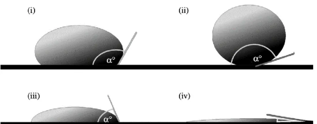
called hydrophobic surfaces (Figure 1.3 i). When water forms spherical droplet on the surface and WCA is more than 150°, the surface termed superhydrophobic (Figure 1.3 ii). Surfaces with WCA more 10° to 90° are called hydrophilic (Figure 1.3 iii). When water spreads and WCA is less 10°, the surface is called superhydrophilic (Figure 1.3 iv) [49].
Figure 1.3: Representation of 4 wettability regimes. (i) hydrophobic surface 90°<WCA<150° (ii) superhydrophobic surface WCA>150° (iii) hydrophilic surface 10°<WCA<90° and (iv) superhydrophilic surface WCA<10° respectively. Adopted by Ref [49]
1.2 Superhydrophilicly Patterned Superhydrophobic
Surfaces
In nature, the amazing examples of surfaces are found and inspires us to design new functional surfaces. The Namib Desert beetles are one of them. The insect has bumpy surface which contains hydrophobic waxy and hydrophilic non waxy regions; using this ‘functional back’, they are able to collect water droplet from fog using this their functional backs. Figure 1.4 shows adult female desert beetle, its hydrophilic non-waxy region of the back and SEM of depressed area. Water droplets nucleates the hydrophilic regions and then droplet grows to specific size after it detached and rolls on the waxy regions to the beetle mouth.[50]
21
Figure 1.4: Desert beetle and its ‘functional back’. (a) Adult female desert beetle (b) hydrophilic non-waxy region of the back and (c) Scanning electron micrograph of the textured surface of the depressed areas. Adopted by Ref [50]
Desert beetle inspired functional surfaces (i,e.,extreme wettability contrast by combination of superhydrophilic and superhydrophobic regions at the micro scale) are used wide range of applications such as water harvesting [7-10], open-air microfluidics [11-12]and surface tension-confined liquid flow in microfluidics.[37][38][39][40] In particular, precise control of the wetted and non-wetted patterns on a single surface allows the formation of ordered droplet arrays and easy droplet manipulation as well as the immobilization and easy-handling of water-dispersed materials including nanoparticles, biomolecules and cells [35-36]. Therefore, patterned superhydrophobic surfaces have attracted significant research interest for high-throughput biological and chemical screening [51-54]. Figure 1.5 shows example of the superhydrophobic/superhydophilic micropatterned surfaces; surface-tension confined microchannel, ordered droplet array and controlled bioadhesion [51-53].
Figure 1.5: Example of the applications of superhydrophobic/superhydophilic micropatterned surfaces. (a) Surface tension confined microchannels: dye gradient. Adopted by Ref [51] (b) close-positioned order droplet arrays. Adopted by Ref [52] (c) Fluorescent cells cultured on a patterned substrate for 48 h. Adopted by Ref [53]
22
1.3 Organically Modified Silica Surfaces
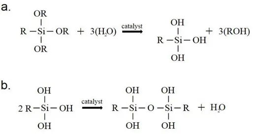
Many successful methods are reported to make functional surfaces, among these methods, organically modified silica are preferred due to superior properties such as mechanical and thermal stability, flexibility and mild, cost-effective synthesis and coating conditions.[17, 56] Organically modified silica (ormosil) is organic-inorganic hybrid material that contains interconnected silaxone (Si-O-Si) backbone and organic groups connected to the backbone which incorporate rigidity of inorganics and flexibility of polymer, respectively [57]. It is produced from via the sol-gel reaction of organotrialkoxysilanes monomers. Reaction mechanisms are shown in Figure1.6 The monomer (empirical formula RSi(OR)3 ) first hydrolyzed via alkoxy (OR) group under
acid or base catalysis, then condensated under base or acid catalysis to forming gel network and non-hydrolyzed organic functional (R) group remains same throughout the reaction.[58, 59] Ormosils can possess the mechanical and thermal stability of inorganic (silica) groups besides functionality and flexibility of organic groups.[60]
Figure 1.6: Sol-gel reaction mechanisms of ormosil. (a). Hydrolyzation of the organosilane monomer. (b). Condensation hydrolyzed monomers
Ormosil properties such as wettability, porosity, flexibility are easily tailored with using different type catalysis, solvent, monomers and reaction conditions accordingly with the targeted application [4, 5, 17, 61, 62]. Example of functional surfaces, were prepared from ormosil, are shown in Figure 1.7. Superhydrophobic and flexible
23
hydrophobic antireflective ormosil coatings were prepared on glass and polymer substrates.[17, 61]
Figure 1.7: Functional surfaces prepared from ormosil. Photographs of (a) Superhydrophobic thin film on glass substrate with water contact angle 178°. Adopted from Ref [17] (b) Bent nanoporous film coated polymer substrate (PEI). (c) Nanoporous ormosil partially coated glass slide. Coated parts reflect less light indicating anti-reflective property. Adopted from Ref [61]
24
Chapter 2
Transparent Superhydrophobic Coatings with
Robust Cassie State of Wetting
2.1 Introduction
The Cassie state of wetting provides a large apparent water contact angle with low contact-angle hysteresis and results in a roll-off superhydrophobic surface, which is desired for practical applications such as self-cleaning windows and solar panels [4, 23, 63], underwater drag reduction [48, 64], and anticorrosion coatings [16].
Although, the Cassie state of wetting (roll-off) can easily and irreversibly transform to the Wenzel state of wetting (sticky) under external stimuli such as pressure, vibration, droplet impact and droplet evaporation by complete filling of the air pockets with water [29-31]. The poor stability of the Cassie state remains as an unsolved drawback against practical applications of superhydrophobic surfaces [31]. Particularly, the applications that require outdoor or underwater operation, where surfaces are exposed to external conditions such as droplet impact or hydrostatic pressure, require a robust Cassie state. Several authors have investigated the parameters that affect the stability of the Cassie state in superhydrophobic coatings [23, 31, 65-78].
However, in almost all of these studies, lithographically fabricated silicon or poly(dimethylsiloxane) (PDMS) pillars were used [31, 65-68, 70-74], which are not suitable for practical applications because of their high cost, limited material choice,
25
and inefficiency for large-area fabrication. In addition, in none of these studies were fabricated surfaces optically transparent, which is a prerequisite for many applications of nonwetting coatings such as self-cleaning windows and solar cells in terms of the appearance and device performance [4, 23]. Therefore, facile fabrication methods for transparent superhydrophobic surfaces with a stable Cassie state of wetting are still needed.
In this chapter, we investigated the effect of different levels of surface topography on the stability of the Cassie state of wetting in large-area and transparent superhydrophobic coatings. Three different organically modified silica (ormosil) coatings, (i) nanoporous hydrophobic coating (NC), (ii) microporous superhydrophobic coating (MC), and (iii) double-layer superhydrophobic coating with nanoporous bottom and microporous top layers (MNC), were prepared on glass surfaces. The stability of the Cassie state of coatings against the external pressure was examined by applying compression/relaxation cycles to water droplets sitting on the surfaces. The changes of the apparent contact angle, contact-angle hysteresis, and sliding-angle values of the surfaces before and after compression cycles were studied to determine the Cassie/ Wenzel transition behavior of the surfaces. In addition, water droplets were allowed to evaporate from the surfaces under ambient conditions, and the changes in the contact angles and contact-line diameters with increasing Laplace pressure were analyzed. We demonstrated that, upon combination of coatings with different levels of topography (i.e., MNC), it is possible to fabricate transparent superhydrophobic surfaces with extremely stable Cassie states of wetting on glass surfaces.
This work published on the ACS Applied Materials&Interfaces (2014, 6, 9680-9688) journal. Reproduced with permission from The American Chemical Society.
2.2 Experimental Section
Materials: Methyltrimethoxysilane (MTMS), oxalic acid, and ammonium
hydroxide (25%) were purchased from Merck (Germany), and dimethyl sulfoxide (DMSO) and methanol were purchased from Carlo-Erba (Italy). All chemicals were used as received.
26
Preparation of NC: Ormosil coatings were prepared according to our previous
report [61]. Initially, 1 mL of MTMS was dissolved in 2 mL of DMSO, and 0.5 mL of an oxalic acid solution (10 mM) was slowly added to the mixture and stirred for 30 min. Then 0.42 mL of an ammonia solution (25%) and 0.19 mL of water in 5 mL of DMSO were added, and the solution was further stirred for 15 min. Finally, the solution was left for gelation at 25 °C. The gels are typically formed in about 1 h. After gelation, approximately 20 mL of methanol was added onto the gels and incubated for at least 6 h at 25 °C to remove DMSO and unreacted chemicals. This treatment was repeated for four times to ensure complete removal of DMSO and other chemical residues. After washing, 12 mL of methanol was added onto the gels and gels were sonicated using an ultrasonic homogenizer for 45 s at 20 W to obtain ormosil colloids that are suitable for thin-film deposition. Then ormosil colloids were spin-coated on clean glass substrates at 2000 rpm and dried at room temperature overnight. To increase the integrity and hydrophobicity, coatings were heat-treated at 450 °C for 1 h.
Preparation of MC: The superhydrophobic microporous coatings were prepared
according to our previous report [17]. First, 1 mL of MTMS was dissolved in 9.74 mL of methanol. Then 0.5 mL of an oxalic acid solution (1 mM) was added to the mixture and gently stirred for 30 min. The mixture was left for hydrolysis for 24 h at room temperature. After hydrolysis, 0.42 mL of an ammonia solution (25%) and 0.19 mL of water were added slowly to the mixture, and the reaction mixture was stirred for 15 min. The solution was left for 2 days at 25 °C for gelation and aging. After aging of the gel network, 12 mL of methanol was added onto the gels and gels were sonicated using an ultrasonic homogenizer for 45 s at 20 W to obtain ormosil colloids. Then ormosil colloids were spin-coated on clean glass substrates at 2000 rpm and dried at room temperature overnight. To increase the integrity and hydrophobicity, coatings were heat-treated at 450 °C for 1 h.
Preparation of MNC: A double-layer coating was prepared by successive spin
coating of ormosil colloids. Initially, a nanoporous layer (bottom layer) was spin-coated on clean glass substrates at 2000 rpm and dried at room temperature overnight. Then a microporous layer (top layer) was spin-coated on the nanoporous layer at 2000
27
rpm and dried at room temperature overnight. Finally, double-layer coatings were cured at 450 °C for 1 h.
Characterization: The surface topography of the coatings was investigated with
scanning electron microscopy (E-SEM; Quanta 200F, FEI) at high vacuum after coating with 5 nm of gold or platinum. Atomic force microscopy (AFM; XE-100E, psia) was used in noncontact mode to characterize the surface morphology and roughness of the coatings. Root-mean-square (rms) roughness values were calculated from three separate AFM images of the coatings, all of which were obtained from 10 × 10 μm2 area. The thicknesses of the coatings were measured with an ellipsometer (V-Vase, J. A. Woollam). Optical transmission experiments were performed with a UV−vis spectrophotometer (Cary 5000, Varian). Contact-angle measurements were performed using a angle meter (OCA 30, Dataphysics). For static contact-angle measurements, 10 μL of water droplets was used with the Laplace−Young fitting. Advancing and receding angles were measured by the addition and subtraction of 5 μL of water to/ from the 10 μL of droplets sitting on the surfaces. Sliding-angle measurements were performed using 10 μL of water droplets.
2.3 Preparation and Characterization of Ormosil
Coatings
MC and NC transparent ormosil coatings on glass surfaces were prepared according to previous reports [17, 61]. MNCs were prepared by the subsequent coating of these two ormosil films: a dual-layer coating with NC as the bottom layer and MC as the top layer.
The Figure 2.1 shows the SEM images of ormosil surfaces. MC demonstrated microporous and rough surface topography (Figure 2.1 a, d). An underlying glass substrate can be observed through the openings of the coating (orange outlined area in Figure 2.1 a). On the other hand, NC fully covers the surface and demonstrates nanoporous and uniform surface topography (Figure 2.1 b, e). Both layers of MNC coating can be clearly distinguished in the SEM image: rough microporous structure of MC at the top and nanoporous NC at the bottom (Figure 2.1 c, f).
Lower-28
magnification SEM images are provided in the Figure 2.1 d-f to demonstrate the uniformity of the coatings.
Figure 2.1: SEM images of ormosil coatings. (a-c) High magnification SEM images of MC, NC, and MNC, respectively. The glass surface exposed through the openings in MC is outlined in orange. In the MNC, the bottom NC is outlined in orange. Low magnification SEM images of the coatings. (d-f) MC, NC and MNC. Arrows indicate the underlying glass substrate in (d) and NC in (f).
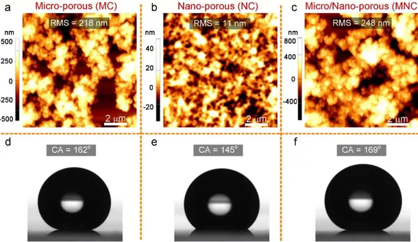
Average surface roughness values of the coatings were calculated from their three separated AFM images (10 × 10 μm2) and are given in the first row of Figure 2.2 a-c
with the representative AFM images of the surfaces. As can be expected, MC and NC have high (218 ± 18 nm) and low (11 ± 2 nm) rms surface roughness values, respectively. The surface roughness of double-layer MNC is on the same order with MC, 248 ± 3 nm.
Because of the low-energy surface methyl groups, coatings are intrinsically hydrophobic. In addition to the hydrophobic surface chemistry, their micro/nanostructured surfaces provide superhydrophobicity. The MC demonstrates roll-off superhydrophobicity (Cassie state) because of its rough and hydrophobic
29
surface with a water contact angle of 162° and a sliding angle of smaller than 1° (Figure 2.2 d). In comparison, even if the NC surface is also highly hydrophobic with a water contact angle of 145°, water droplets pinned to the surface (Wenzel state) because of its low surface roughness (Figure 2.2 e). MNC demonstrated a Cassie state superhydrophobic property with water contact and sliding angles similar to those of the MC (Figure 2.2 f).
Figure 2.2: (a-c) AFM images of MC, NC, and MNC, respectively. (d-f) Photographs of water droplets sitting on MC, NC, and MNC, respectively.
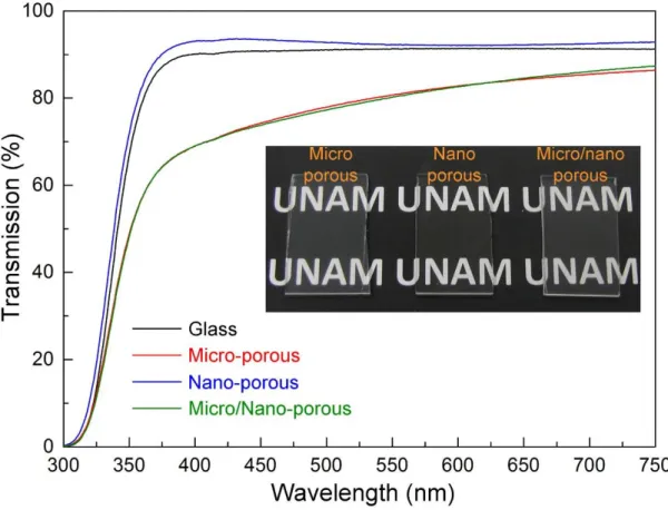
Transparency of superhydrophobic coatings is desired for many practical applications including self-cleaning windows and solar panels. [4, 23, 25, 63, 79-81] Figure 2.3 shows the transmission spectra of the ormosil coatings. Despite its high surface roughness value, MC demonstrates high transparency (up to 85%) in the visible wavelengths. The slight decrease in the transmission compared to the bare glass is due to the light scattering from its microporous surface, which is more pronounced in smaller wavelengths.[82] The transmission of NC is even higher than bare glass (i.e., antireflection property) because of its smooth surface and porous nature, which introduces a gradual refractive index change and reduces the reflectance of the glass.[4,
30
61, 83] Lastly, the transmission spectrum of double-layer MNC is almost identical with that of MC because of the same order of their surface porosity and roughness.
Figure 2.3: Transmission spectra of ormosil coatings and an uncoated glass substrate. All of the coatings are highly transparent at the visible wavelengths. The inset shows a photograph of transparent coatings.
2.4 Compression Experiments
Squeezing water droplets between two surfaces is often used to investigate the stability of the Cassie state of wetting of superhydrophobic coatings against the external pressure.[46, 69, 70, 76] During compression of a droplet placed on a superhydrophobic surface, pressure differences as high as 300 Pa can be generated depending on the distance between two surfaces and the apparent contact angles of the surfaces.[46] The pressure difference generated during compression can be calculated using the following Laplace equation, when droplet radius is much higher than interplanar distance:[46]
31
∆P = γ(cosθb + cosθt)/x, for x<< R, 2.1
where γ is the surface tension of water, R is the radius of the droplet, x is the gap between the top and bottom surfaces, and θb and θt are the water contact angles of the bottom and top surfaces, respectively.
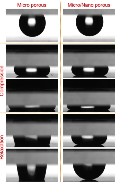
For compression experiments, first a droplet (10 μL) was placed on a NC surface (top plane) and slowly approached a bottom plate (MC or MNC) to squeeze the water droplet between two surfaces up to an interplanar distance (Δx) of ∼0.4 mm. Then we slowly relaxed the top surface. Figure 2.4 shows the frames of the water droplets during squeezing and relaxation between NC and MC (left column) and NC and MNC (right column). In the first stages of compression (the second row in Figure 2.4), the bottom contact lines largely preserved their high water contact angle values for both MC and MNC. However, for the highest compression (the third row in Figure 2.4), a significant decrease in the apparent contact angle of MC was observed, which suggests a transition between the Cassie and Wenzel states. [46, 69] On the other hand, double-layer MNC preserved the high water contact-angle value even at this high compression. The wetting difference between two coatings is more obvious during relaxation. It can be clearly seen from the fourth and fifth row in Figure 2.4 that after compression a water droplet strongly sticks to the MC surface, indicating the Wenzel transition; quite the reverse, a droplet on the MNC surface relaxes easily without changing its spherical shape, indicating that the MNC surface preserved the Cassie state.[69, 70] Figure 2.5a shows the in situ contact-angle measurements during compression of the surfaces, and Figure 2.5b shows the generated pressure as a function of Δx. The contact angle of the MC sharply decreased below 150° in the first stages of squeezing. On the other hand, the water contact angle of the MNC is larger than 150° even at the lowest Δx value. The generated Laplace pressure difference (eq 2.1) at highest compression when interplanar distance x=0.4 mm (Figure 2.5b) is almost 2-fold higher for the MNC because it demonstrates higher water contact-angle values than the MC during compression. From Figure 2.5b, it can be observed that, for the MC, Cassie to Wenzel transition occurred at a pressure difference of roughly around 80 Pa, whereas no transition was observed for the MNC even at a pressure difference of 260 Pa.
32
Figure 2.4: Compression experiments using the NC as the sticky hydrophobic top plate. Photographs of the water droplets compressed and released on micro-porous MC (left column) and micro/nano-porous MNC (right column).
33
Figure 2.5: (a) Contact-angle change of coatings during compression. b) Generated Laplace pressures for coatings during compression. Wenzel transition was observed for the MC at the first stages of compression; on the other hand, the Cassie state was preserved in the MNC even at the highest compression
Besides the decrease in the apparent contact angle, increases in the contact-angle hysteresis and sliding angle are indicators of Cassie to Wenzel transition. [47] Surfaces with the Cassie state of wetting demonstrate low contact-angle hysteresis values and smaller sliding-angle values due to easy roll-off of the droplets; however, for the Wenzel state of wetting, droplets pin to the surfaces with high contact-angle hysteresis
34
values. To measure the water contact and sliding angles and contact-angle hysteresis of MC and MNC after droplet relaxation, we designed a compression experiment where a water droplet (10 μL) is squeezed between two identical surfaces (MC or MNC; Figure 4, inset) and released. Figure 2.6 shows the contact angles of surfaces after release from a compression distance of 1 mm. The contact angle of a released droplet on the MC sharply decreases to 127°, which is in good accordance with initial compression experiments. In contrast, there is only 5° difference in the contact angles of the MNC before and after squeezing. Figure 2.7a shows the water droplet sliding angles before and after the compression test. Before squeezing, both surfaces were highly water repellent with sliding angles lower than 1°. However, a droplet on the MC strongly sticks to the surface after pressure release, and it remains pinned even at 90° tilting. For the MNC, although an increase in the sliding angle after pressure release was observed, the droplet can easily roll off from the surface at 15° of tilting. Figure 2.7b shows the contact-angle hysteresis of the surfaces before and after compression. Both surfaces have contact-angle hysteresis values of around 2° before compression. After compression, the increase in the contact-angle hysteresis is much more pronounced for MC (∼13°) than for MNC (∼7°).
Figure 2.6: Droplet squeezing between two identical surfaces. Contact angles of surfaces before and after compression. The inset shows the squeezed water droplet between two MNC surfaces. There is only a slight decrease in the contact angle of the MNC after compression. The large decrease in the MC shows loss of the superhydrophobic property.
35
Figure 2.7: Droplet squeezing between two identical surfaces. (a) Sliding angles of surfaces before and after compression experiments for the MC (left column) and MNC (right column). A droplet on the MC sticks to the surface after compression due to Wenzel transition, whereas a water droplet on the MNC easily rolled off from the surface at 15° tilting angle, indicating that the water droplet is still at the Cassie state. (b) Contact-angle hysteresis of the surfaces before and after compression. The increase in contact-angle hysteresis is significantly larger for the MC.
The excellent Cassie state stability of the MNC can be attributed to its double-layer structure (Figure 2.8). For the MC, the contact line gradually slides down from the walls of microporous structures with increasing pressure; after a critical pressure difference, the contact line touches the hydrophilic glass substrate and pins to the surface instantly (transition to the Wenzel state). On the other hand, for the MNC the bottom NC layer prevents interaction between the glass substrate and contact line. Under a critical pressure difference, the contact line must touch the NC surface, and at
36
that point, transition to the nano-Cassie state from the initial micro-Cassie state can be expected.[74] After removing the pressure, contact line can partially recover to the initial micro-Cassie state. The increase in contact-angle hysteresis and the sliding angle and the slight decrease in the apparent contact angle support the proposed partial transition model between nano- and micro-Cassie states.
Figure 2.8: Schematic representation of the proposed model for the excellent Cassie state stability of the MNC coatings. For the MC, the contact line gradually slides down from the walls of microporous structures with increasing pressure; after a critical pressure difference, the contact line touches the hydrophilic glass substrate and pins to the surface instantly (transition to the Wenzel state). On the other hand, for the MNC, the bottom NC layer prevents interaction between the glass substrate and contact line.
2.5 Evaporation Experiments
During evaporation of water droplets from superhydrophobic surfaces, Laplace pressures as high as a few thousand pascal can be generated because of size reduction of the droplet, which is around 1 order of magnitude larger than the pressure difference
37
generated during compression experiments.[84, 85] Therefore, to further demonstrate the Cassie state stability of the MNC, we performed evaporation experiments by placing water droplets (6 μL) to the surfaces and allowing their evaporation at ambient conditions (approximately at 22 °C and 23% humidity).
Figure 2.9 shows time-dependent evaluation of the shape of water droplets on the MC and MNC. A water droplet on the MC lost its spherical shape gradually during evaporation and pinned to the surface, which indicates the Wenzel transition. On the other hand, a water droplet on the MNC preserved its spherical shape even at the last stages of evaporation, which shows that the water droplet was still at the Cassie state.
Figure 2.9: Evaporation experiments: Photographs of water droplets sitting on the MC (upper row) and MNC (lower row) at different instants of the evaporation process. Wenzel transition was observed for a droplet sitting on the MC at around 18 min. A water droplet on the MNC, on the other hand, preserved its spherical shape even at the final stages of evaporation, indicating the excellent Cassie stability of this coating.
Figure 2.10 shows the apparent contact-angle change of the surfaces during evaporation. The contact angle of the water droplet on the MC continuously decreased to 120° in about 22 min and sharply decreased to almost 0° after approximately 30 min, where the droplet completely evaporated. The contact angle of the water droplet on the MNC decreased similarly to the MC for the first 10 min. However, at this point, a jump in the contact angle occurred and it almost completely recovered to its initial value. Then it started to decrease again, and a second jump occurred after 19 min. Similarly, a third jump was observed after 31 min. At the 35th minute, the size of the
38
droplet largely reduced, and after approximately 10 s, it completely evaporated. The reason for this behavior will be discussed in more detail below. Note that the time required for complete evaporation of a droplet is slightly lower on the MC compared to the MNC, which is due to the increased evaporation rate after Wenzel transition (i.e., improved wettability) for this coating. To compare the Cassie state stability of coatings during droplet evaporation, we calculated the Laplace pressures [65] (ΔP = 2γ/R, where γ is the surface tension of water and R is the droplet radius with a spherical shape) at the points where the contact angle of the water droplets decreases to around 120° (t = 21 and 35 min for the MC and MNC, respectively; Figure 6b, inset). The Laplace pressure at this point for the MNC (1620 Pa) is almost 7-fold higher than that of the MC (248 Pa). We note that the Cassie state stability of the MNC is even better than that of the Lotus leaf, where the same transition was observed slightly above 400 Pa [65]. The difference between the pressure values where the contact angles of the MC and MNC surfaces and Lotus leaf reached 120° demonstrates the enhanced Cassie state stability of the MNC surface. The contact-angle decrease rate of the MNC surface is much slower compared to that of both the MC surface and Lotus leaf, and Wenzel transition occurs at much later stages of evaporation.
Figure 2.10: Contact angles of the surfaces during evaporation experiment. The inset shows the generated Laplace pressures at the point where contact angles of the surfaces decrease below 120°.
39
For droplet evaporation experiments, four evaporation behaviors were defined in the previous studies:[67, 86-92] (i) the constant-contact-line (CCL) state, where the contact-line diameter is constant and the contact angle is decreasing, (ii) the constant-contact-angle (CCA) state, where the contact angle is constant and the contact-line diameter is decreasing, (iii) the stick−slip (S−S) behavior, where the droplet baseline retracts step by step, resulting in sudden increases in the contact angle,[92] and (iv), the mixed state, where both the contact angle and contact-line diameter are decreasing. To identify the evaporation modes of our surfaces, we investigated the contact-line diameters of droplets during evaporation (Figure 2.11). For the MC, the CCL mode was observed in the first 25 min, where the diameter of the contact line is almost constant and the apparent contact angle is constantly decreasing (Figure 2.10 and 2.11). Also, at the last stages of evaporation, a mixed mode was observed. For the MNC, more complicated evaporation modes were observed (Figure 2.11). In the first 10 min, a CCL mode similar to that for the MC was observed. However, after this point, a sudden decrease in the diameter of the contact line was observed. Note that a sudden decrease in the contact-line diameter occurred at the same time with a jump in the contact angle. This behavior has been observed previously on rough hydrophobic surfaces and is called as “stick−slip”, referring to successive “pinning−depinning” of droplets during evaporation.[71, 93-95] As in contact-angle measurements, there are three abrupt changes in the baseline diameter of the MNC where the S−S behavior was observed, and between these jumps, the contact line can be approximated to be constant (CCL mode). Also, at the last stages of evaporation, the mixed mode was observed.
40
Figure 2.11: Change of the water droplet contact-line diameter during evaporation. A CCL mode was observed for the MC. For the MNC, sudden decreases in the contact-line diameter were observed. This behavior, where the contact line of the droplet retracts and the contact angle increases suddenly, is known as stick−slip (S−S) behavior, referring to successive “pinning−depinning” of the droplet.
The CCL modes observed for both coatings can be explained by analyzing the forces at the triple contact line.[67, 96] At t = 0, a droplet is in the equilibrium and the contact line is fixed. Then water starts to evaporate and therefore the droplet volume is continuously decreasing, which results in a decrease in the contact angle. The decrease in the contact angle disturbs the equilibrium between forces acting on the droplet and generates a radial force toward the center of the drop. This force (i.e., depinning force) retracts the contact line and recovers the initial contact angle. The depinning force (FD) can be expressed as [96]:
FD = 2Rbσlg (cosθt - cosθi) 2.2
where Rb is contact-line radius, σlg is the surface tension of water, θt is the contact angle
at a certain interval during evaporation, and θi is the initial contact angle. Figure 2.12a
shows the depinning force generated during the evaporation process for the MNC. We observed that, during evaporation, first a depinning force around 5 mN was generated
41
and then the droplet relaxed by retraction of the contact line, and this cycle was repeated three times. Figure 2.12b shows the contact-line retraction between the 20th and 21th minutes. After contactline retraction, the apparent contact angle of the droplet reaches its initial value, which indicates total relaxation. Note that no relaxation was observed for the MC even at depinning forces larger than 100 mN, which shows that the water droplet on the MC strongly pins to the surface during evaporation (see the Figure 2.13).
Figure 2.12: Force generation and relaxation of the contact line for the MNC. (a) Depinning force generation and its relaxation during evaporation. Red areas indicate the force generation,
42
and blue areas indicate the relaxation regions. (b) Baseline retraction for the MNC between 20 and 21 min. After baseline retraction, the baseline diameter significantly decreased and the contact angle increased.
Figure 2.13:.Generation of force needed for depinning of contact line during evaporation for microporous coating. No force relaxation was observed for this coating.
43
Chapter 3
Patterning Superhydrophobic Ormosil
Surfaces for Controlled Wetting and
Bioadhesion
3.1 Introduction
Over the past decade, a number of successful methods have been introduced to prepare functional superhydrophilic-superhydrophobic micropatterned surfaces including photo-induced chemical modification, [53, 97-100] plasma treatment,[8, 101-103] ink-printing,[10, 104-106] direct laser writing,[56] UV exposure [107-109] and photo-catalytic decomposition.[9, 110-112] However, most of the above-mentioned methods use at least two or more production steps; e.g. pre-modification of the surfaces with either hydrophilic or hydrophobic materials, followed by post-modification to form wetted and non-wetted patterns, which complicates the fabrication. In addition, stability and control over the degree of wettability are important for practical applications of the patterned superhydrophobic surfaces. Particularly for biological systems, wettability plays a key role on the control of cell adhesion and protein adsorption.[32-34]
In an alternative approach, Mano and co-workers prepared patterned superhydrophobic polymeric platforms with well-controlled wettability using UV/O treatment which offers simplicity and reduced cost.[11, 54] However, when UV/O is
44
applied on polymer surfaces, contact angle increases over time (hydrophobic recovery effect) due to the flexibility and reorganization of the bonds within the polymer chains [113-115].
In this chapter, the facile generation of robust hydrophilic patterns on superhydrophobic organically modified silica (ormosil) surfaces using a one-step rapid method was introduced. Superhydrophobic hybrid silica surfaces have the potential to address the above-mentioned problems; they eliminate the modification steps prior to patterning since hydrophobic surface chemistry and high surface roughness were combined in one-pot approach. They also exhibit higher chemical stability as well as easier functionalization relative to polymers. In order to create fully isolated wetted and non-wetted patterns, certain regions of the as-prepared surfaces were treated with UV/O which modified the surface two-dimensionally by switching its chemistry from methyl groups to hydrophilic silanol groups without changing morphology. We demonstrated that the degree of wettability of the hydrophilic patterns can be controlled depending on the UV/O treatment duration. Extremely hydrophilic regions with water contact angles (WCA) nearly 0º can be formed while the unmodified surface domains exhibit WCA close to 170º. One can rapidly form arrays of droplets on the patterned surfaces by dipping them into aqueous media or can dispense microdroplets individually to distinct micron-sized superhydrophilic spots. We further demonstrate that biomolecules such as albumin can selectively adsorb and be confined on the hydrophilic domains where the degree of wettability significantly influences the amount of adsorption. Superhydrophilic-superhydrophobic patterns are also intact under bending impacts owing to the robustness and flexibility of ormosil coatings. In addition, patterned ormosil coatings retained their wettability performance for the storage periods of several months. Superhydrophilic-patterned ormosil coatings can be potentially used in drug screening, cell microarrays and microfluidics with their low-cost preparation, wide pattern diversity and robustness.
45
3.2 Experimental Section
Materials. Methyltrimethoxysilane (MTMS), oxalic acid and ammonium
hydroxide (25%) were purchased from Merck (Germany), methanol was purchased from Carlo-Erba (Italy), fluorescein isothiocyanate-bovine serum albumin conjugate (FITC-BSA, with MW of 66 and 389.4 kDa for BSA and FITC, respectively) was purchased from Sigma-Aldrich (USA). All chemicals were used as received. Ultra-pure water (18.2 MΩ.cm at 25°C) obtained using a Millipore Milli-Q water purification system (Billerica, USA) was used in all experiments.
Preparation of Superhydrophobic Ormosil Coatings. Ormosil superhydrophobic
coatings were prepared via two step sol-gel reaction as introduced in our previous report.[17] First, 1 mL of MTMS was dissolved in 9.74 mL of methanol. Following 15 min stirring of the solution, 0.5 mL of 1 mM oxalic acid solution was added dropwise and the solution gently stirred for 30 min. Then, the mixture was left to hydrolyze the organosilane precursor completely for 24 h at room temperature. After the hydrolysis step, 0.19 mL of water and 0.42 mL of ammonia solution (25 %) were added slowly as the catalyst of the reaction and the mixture was stirred for further 15 min. The resultant mixture was left for 2 days at 25 °C for complete gelation and aging. After aging the gel network, 9 mL of methanol was added onto the gel and gel was sonicated using an ultrasonic liquid processor for 45 s at 20 W to obtain homogeneously dispersed ormosil colloids. The ormosil colloids were coated on various clean substrates (glass, silicon, polymer) at 3000 rpm for 45 s using spin-coater and were dried at room temperature overnight.
Mask preparation. Commercial cellulose acetate papers were patterned with CO2
laser cutter (Zing laser system, Epilog laser, U.S) to obtain hollow masks.
Preparation of superhydrophilic and patterned surfaces. Superhydrophobic
ormosil coated surfaces were exposed UV-ozone for certain time (5-60 min) using commercial surface cleaning system (PSD-UV, Novascan Technologies, U.S) at ambient condition without extra oxygen. The cleaning system was used mercury lamp with wavelength 254 nm and 185nm. Superhydrophobic surface was covered with hollow mask and treated with UVO for specific time (15, 30, 60 min).
46
Protein Adsorption Studies. Patterned surfaces with 1 mm diameter circular spots
were prepared UVO with different exposure time and dipped to the 1mg/ml FICT-BSA solution for 30s and then gently washed with ultra-pure water.
Bacterial Adhesion. GFP-(green fluorescent protein) expressing E. coli with size of
2 μm was proliferated in LB media at 37 °C under CO2 environment. Then, LB was precipitated and bacteria was dispersed in PBS (phosphate buffer solution, pH~7.4) medium. Approximately 200 μL of the bacteria suspension was rolled from the superhydrophilic-patterned ormosil surface and tiny droplets of the suspension was distributed to the wetted spots.
Characterizations. XPS, SEM, CA, Confocal, Image J Chemical analysis of the
surfaces were performed using X-ray photoelectron spectroscopy(XPS) (Thermo Fisher Scientific, U.K) with Al K-α monochromator (0.1 eV step size, 12kV, 2.5mA, spot size 400 µm) and an electron take-off angle of 90°. Avantage software package was used peak calibration and peak fitting. Surface morphology of the surfaces were analyzed with Scanning Electron Microscope (SEM) (E-SEM, Quanta 200F, FEI) under high vacuum condition at 10kV after coated with 6 nm thick gold-platinium layer. Static contact angle (WCA) of the surfaces were measured using contact angle meter (OCA 30, Dataphysics). 4 µL water droplets were used for the measurements and the measurements were analyzed with Laplace-Young. Confocal images were at 10X objectives taken with a confocal microscope (Model LSM 510, Zeiss, Germany). FITC-BSA was excited with Argon laser at 488 nm and emission collected over 505 nm with photomultiplier tubes. ImageJ program was used quantifying fluorescent intensity.
3.3 UV/Ozone Treated and Untreated Surfaces:
Preparation and Characterization
Superhydrophobic coatings were prepared from organically modified silica (ormosil) hybrid nanostructures and then patterned as superhydrophilic-superhydrophobic using a rapid and simple UV/O treatment step where hydrophobic organic moieties were gradually decomposed. Ormosil nanostructures were
47
synthesized via a template-free sol-gel reaction: acid-catalyzed hydrolysis followed by base-catalyzed condensation using methyltrimethoxysilane (MTMS) as the organosilane precursor.[17] Methoxy groups of the organosilane monomers are hydrolyzed and condensed through siloxane bonds forming silica network.[59] On the other hand, the organic methyl groups remain non-hydrolyzed and unmodified throughout the whole sol-gel process. Continued crosslinking of the networks leads to the formation of ormosil gel which is a highly porous structure due to the macroscopic phase separation of the hybrid particles.[57, 60, 61] After complete gelation, the gel was broken down to form colloidal ormosil solution which was then coated onto glass substrates. The resulting coatings preserved the initial porosity of the gel since methyl groups in the interconnected network prevents the pore collapse during solvent evaporation.[116, 117]
The surface morphologies of ormosil thin films were investigated by SEM. In Figure 3.1a, the SEM of the as-prepared coating revealed the highly porous and phase-separated ormosil structure with both nanometer and micrometer pores. The rough and porous structure combined with the low surface-energy methyl group led to superhydrophobicity of the coating with a static water contact angle (WCA) of 170° (see the inset in Figure 3.1a). When the superhydrophobic surfaces were treated under UV/O, the contact angle started to decrease, and after 1 h treatment, superhydrophilic surfaces with water contact angles of nearly 0° were obtained (see the inset in Figure 3.1b). Figure 1b shows the SEM image of a coating after UV/O treatment for 1 h. The surface morphology and porous structure remained unchanged as the initial state upon treatment (Figure 3.1b).