DEVELOPMENT OF BIOINTEGRATED ELECTROSPUN
NANOFIBERS FOR ENVIRONMENTAL APPLICATIONS
A DISSERTATION SUBMITTED TO
THE GRADUATE SCHOOL OF ENGINEERING AND SCIENCE OF BILKENT UNIVERSITY
IN PARTIAL FULFILLMENT OF THE REQUIREMENTS FOR THE DEGREE OF
DOCTOR OF PHILOSOPHY IN
MATERIALS SCIENCE AND NANOTECHNOLOGY
By
Ömer Faruk Sarıoğlu August 2016
ii
DEVELOPMENT OF BIOINTEGRATED ELECTROSPUN NANOFIBERS FOR ENVIRONMENTAL APPLICATIONS
By Ömer Faruk Sarıoğlu August 2016
We certify that we have read this dissertation and that in our opinion it is fully adequate, in scope and in quality, as a dissertation for the degree of Doctor of Philosophy.
Tamer Uyar (Advisor)
Mahinur Akkaya
Mehmet Mutlu
Hasan Tarık Baytekin
Urartu Özgür Şafak Şeker
Approved for the Graduate School of Engineering and Science
Levent Onural
iii
ABSTRACT
DEVELOPMENT OF BIOINTEGRATED ELECTROSPUN
NANOFIBERS FOR ENVIRONMENTAL APPLICATIONS
Ömer Faruk Sarıoğlu
Ph.D. in Materials Science and Nanotechnology Advisor: Tamer Uyar
August 2016
Electrospinning is an easy and economical production technique to produce nanofiber/nanofibrous webs from different polymers, polymer mixtures, inorganic materials, supramolecular structures and composite materials. These nanofibers have unique physical/chemical properties due to their large surface areas and highly nanoporous structures. Since these nanofibers have superior properties, various functions and can be modified by physical/chemical methods, they have a great potential to be applied in membrane/filter applications.
Bioremediation is a commonly used technique for removal of water contaminants, and different kinds of bacteria have been used for bioremediation of water systems. Use of biointegrated hybrid materials is an alternative approach for bioremediation, and this may provide higher efficiency, ease of application and reusability. As a carrier system, electrospun nanofibers are suitable materials for integration of bacteria, since electrospinning can allow production of nano/micro scale composites with tunable physical/chemical properties.
In this thesis, it was aimed to integrate bacteria that have bioremediation capability with electrospun nanofibers by using immobilization/encapsulation
iv
techniques and test the potential of these biocomposites for treatment of contaminated water systems. The integration of bacteria that can remediate ammonium, heavy metal, textile dye and surfactant with electrospun nanofibers was achieved by two different approaches. In the first approach, bacterial cells were physically immobilized on cellulose acetate (CA), polysulfone (PSU), polystyrene (PS), polycaprolactone (PCL) and polylactic acid (PLA) electrospun nanofibers. In order to observe effects of nanofiber/nanofibrous web morphology and arrangements on the immobilization of bacteria, some of these nanofibers were produced as porous, parallelly arranged, and with different diameters. In the second approach, by using polyvinyl alcohol (PVA) and polyethylene oxide (PEO) polymers, simultaneous encapsulation of bacteria in nanofiber structures was provided. Afterwards, all these different kinds of biocomposites were tested for their remediation potential in accordance with the intended use of the integrated bacteria.
Keywords: electrospinning, nanofiber, bacteria, heavy metal, textile dye,
v
ÖZET
ELEKTROSPİN YÖNTEMİ İLE ÜRETİLMİŞ NANOLİF
YAPILARA BİYOLOJİK MALZEMELERİN ENTEGRE
EDİLEREK ÇEVRESEL UYGULAMALAR İÇİN
KULLANILMASI
Ömer Faruk Sarıoğlu
Malzeme Bilimi ve Nanoteknoloji Programı, Doktora Tez Danışmanı: Tamer Uyar
Ağustos 2016
Elektrospin yöntemi değişik polimerlerden, polimer karışımlarından, inorganik malzemelerden, supramoleküler yapılardan ve kompozitlerden nanolif/nanoağ elde edilen, kolay ve maliyeti düşük bir üretim tekniğidir. Bu nanolifler, yüksek yüzey alanları ve nano boyuttaki gözenekli (boşluklu) yapıları sayesinde sıra dışı fiziksel/kimyasal özellikler göstermektedirler. Üstün özelliklere, birçok işleve sahip olan ve fiziksel/kimyasal yollarla modifiye edilebilen bu nanolifler özellikle membran/filtre uygulamarında yüksek kullanım potansiyeline sahiptirler.
Biyogiderim yöntemi sudaki kirleticilerin temizlenmesi amacıyla uygulanan yaygın bir tekniktir ve çeşitli türdeki bakteriler sucul sistemlerde biyogiderim yapması amacıyla kullanılmaktadır. Biyoentegre sistemlerin biyogiderim amacıyla kullanımı alternatif bir yaklaşım olup, daha yüksek başarı, uygulama kolaylığı ve tekrar kullanılabilirlik sağlayabilmektedir. Elektrospin edilmiş nanolifler bakteriler için uygun bir tutunma ortamı olabilir, zira elektrospin yöntemi nano/mikro düzeyde kompozit malzemelerin ayarlanabilir fiziksel ve kimyasal özelliklerde üretilmesine olanak sağlamaktadır.
vi
Tez çalışması kapsamında, elektrospin yöntemi ile üretilen nanoliflere, biyogiderim özelliği bulunan bakterilerin immobilizasyon/enkapsülasyon teknikleri kullanılarak entegrasyonu ve elde edilen biyokompozit malzemelerin atık su arıtımındaki potansiyellerinin araştırılması amaçlanmıştır. Amonyum, ağır metal, tekstil boyar maddesi ve surfaktan giderim özelliği gösteren bakterilerin nanoliflerle entegrasyonu iki farklı yaklaşımla gerçekleştirilmiştir. Birinci yaklaşımda, homojen bir morfolojide elde edilen selüloz asetat (CA), polisülfon (PSU), polistiren (PS), polikaprolakton (PCL) ve polilaktikasit (PLA) nanoliflerinin yüzeyine fiziksel yollarla bakteriler immobilize edilmiştir. Nanolif/nanoağ morfoloji veya dizilimdeki değişikliklerin bakteri tutunmasında neden olabileceği farklılıkları incelemek açısından, bu nanoliflerin, gözenekli, paralel dizilimli ve farklı çaplara sahip halleri de üretilerek etkileri incelenmiştir. İkinci yaklaşımda ise, polivinilalkol (PVA) ve polietilenoksit (PEO) polimerleri kullanılarak, bakterilerin eş zamanlı nanolif yapılarına enkapsülasyonu sağlanmıştır. Daha sonra, bu yöntemlerle üretilen biyokompozit malzemelerin entegre edilen bakterinin özelliğine göre endüstriyel atık su arıtımındaki kullanım potansiyelleri test edilmiştir.
Anahtar kelimeler: elektrospin, nanolif, bakteri, ağır metal, tekstil boyar maddesi,
vii
ACKNOWLEDGEMENTS
I would like to thank to everyone whoever contributed to my thesis. My special thanks go to my supervisor Prof. Tamer Uyar, for his encouragement, guidance and support during the course of this research. I am sincerely grateful to Prof. Turgay Tekinay for his active collaboration, support and guidance. I would like to thank to Prof. Urartu Şeker, Prof. Ayşe Begüm Tekinay, Prof. Mustafa Özgür Güler for their support and fruitful discussions. I would like to express my special thanks to my senior peers Dr. Aslı Çelebioğlu, Dr. Nalan Oya San Keskin and Dr. Ayşe Özdemir for their partnership and fellowship in this research. I would like to thank to my other senior peers and colleagues in Functional Nanofibers Group, Dr. Ali Demirci, Dr. Osman Arslan, Dr. Bekir Satılmış, Dr. Anitha Senthahizman, Dr. Brabu Balusamy, Dr. Kugalur Shanmugam Ranjith, Dr. Amaresh Chandra Pradhan, Zeynep Aytaç, Yelda Ertaş, Zehra İrem Gürbüz, Şefika Özcan and Ahmet Fatih Işık for their fellowship and helpful discussions. The Scientific and Technological Research Council of Turkey (TUBITAK, project #114Y264) is acknowledged for funding the research and BİDEB 2211-C scholarship.
I would like to thank to Dr. Gökçe Çelik, Mustafa Güler and Zeynep Erdoğan for their technical assistance and fruitful discussions. I would like to express most sincere thanks to my dear friends; İbrahim Murathan Sektioğlu, Nazım Enes Altan, Yavuz Selim Dağdaş, Süleyman Deniz, Tolga Tarkan Ölmez, Ebuzer Kalyoncu, Alper Devrim Özkan, and Ahmet Emin Topal. I would like to thank to my brothers; Abdullah Soylu, Yunus Emre Barun, Akif Bayram,
viii
Hüseyin Enes Salman, İkram Orak, Mustafa Ürel, Kadir Akbudak and Hasan Barış Geçer. I would like to thank to Fatma Kayacı, Ali Ekrem Deniz, Ruslan Garifullin, Hasan Güner, Taha Bilal Uyar, Muhammad Aref Khalily, Murat Serhatlıoğlu, Mehmet Girayhan Say, Sami Bolat, Şehmus Tohumeken, Yusuf Keleştemur, Burak Güzeltürk, Talha Erdem, Zeliha Soran Erdem, Burcu Gümüşçü, Berna Şentürk, Pelin Tören, Canan Kurşungöz and Nuray Gündüz. I would like to thank my office mates, Tolga Tarkan Ölmez, Ebuzer Kalyoncu, Mehmet Can Yağcıoğlu, Türkan Gamze Ulusoy and Amir Ghobadi. They helped me to work in such a warm and quiet environment.
I would like to acknowledge UNAM (National Nanotechnology Research Center) and I want to thank to all the other members of UNAM.
Finally, I want to express my gratitude to my beloved family, my altruistic mother Hayriye Sarıoğlu, my dearest brother Fatih Semih Sarıoğlu and my fiancee Merve Gülsüm Keskin for their care, support and understanding.
ix
Canım babama,
x
LIST OF ABBREVIATIONS
ABS alkyl benzene sulphonate
CA cellulose acetate
LAS linear alkyl sulphonate
LC-MS liquid chromatography mass spectroscopy
MBAS methylene blue active substances assay
MB methylene blue
OD optical density
PCL polycaprolactone
PEO polyethylene oxide
PLA polylactic acid
PS polystyrene
PSU polysulfone
PVA polyvinyl alcohol
SDS sodium dodecyl sulfate
xi
TABLE OF CONTENTS
ABSTRACT ... iii ÖZET ... v ACKNOWLEDGEMENTS ... vii LIST OF ABBREVIATIONS ... x TABLE OF CONTENTS ... xiLIST OF FIGURES ... xiii
LIST OF TABLES ... xix
Chapter 1: General Introduction ... 1
1. Water pollution and sustainable water management ... 2
2. Bio-based approaches for water sustainability ... 4
3. Electrospun fibrous networks as carrier matrices for development of biointegrated systems ... 6
Chapter 2: Bacteria immobilized electrospun cellulose acetate fibrous webs for ammonium removal ... 9
1. Introduction ... 10
2. Experimental ... 13
3. Results and discussion ... 17
Chapter 3: Bacteria immobilized electrospun fibrous webs for hexavalent chromium remediation ... 27
1. Introduction ... 28
2. Experimental ... 30
3. Results and discussion ... 35
Chapter 4: An easy and effective method for determination of the number of bacteria that are immobilized on electrospun nanofiber surfaces ... 47
1. Introduction ... 48
xii
3. Results and discussion ... 52
Chapter 5: Evaluation of contact time and fiber morphology differences for development of novel surfactant degrading biocomposites ... 60
1. Introduction ... 61
2. Experimental ... 63
3. Results and discussion ... 71
Chapter 6: Evaluation of fiber diameter and morphology differences for electrospun polysulfone fibers on bacterial immobilization and bioremediation performance ... 88
1. Introduction ... 89
2. Experimental ... 91
3. Results and discussion ... 95
Chapter 7: Bacteria immobilized electrospun polycaprolactone and polylactic acid fibrous webs for remediation of textile dyes in water ... 103
1. Introduction ... 104
2. Experimental ... 106
3. Results and discussion ... 112
Chapter 8: Bacteria encapsulated electrospun nanofibrous webs for remediation of methylene blue dye in water ... 123
1. Introduction ... 124
2. Experimental ... 126
3. Results and discussion ... 132
Chapter 9: Conclusion and future perspectives ... 147
LIST OF PUBLICATIONS ... 155
xiii
LIST OF FIGURES
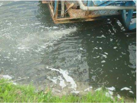
Figure 1: Foaming in an industrial effluent due to contamination of
surfactants………..……3
Figure 2: Schematic representation of the electrospinning set-up...7 Figure 3: Photograph of an electrospun cellulose acetate nanofibrous web...7 Figure 4: (a) Schematic representation of electrospinning process for CA
nanofibers and photograph of CA nanofibrous web (b) photograph of STB1 immobilized CA nanofibrous web and schematic representation of bacterial cells on nanofiber surfaces. (Copyright © 2013, Reproduced from Ref. [18] with
permission from the Royal Society of
Chemistry).………...14
Figure 5: General morphology of Acinetobacter calcoaceticus STB1 under
Scanning Electron Microscope (SEM) at 5000X (a) and 15000X (b) magnification. (Copyright © 2013, Reproduced from Ref. [18] with permission from the Royal Society of Chemistry)..…..………...………….19
Figure 6: SEM micrographs of bacteria-free electrospun CA nanofibers at (a)
2500X and (b) 200000X; and STB1 immobilized nanofibers after 35 days of incubation at (c) 5000X and (d)10000X magnification. (Copyright © 2013, Reproduced from Ref. [18] with permission from the Royal Society of Chemistry)………...………19
Figure 7: Ammonium, nitrite and nitrate levels for: (a) free STB1 cells at initial
ammonium concentration of 50 mg/L; (b) bacteria-free CA web at initial ammonium concentration of 50 mg/L; (c) STB1 immobilized CA web at initial ammonium concentration of 50 mg/L; (d) STB1 immobilized CA web at initial ammonium concentration of 100 mg/L; (e) STB1 immobilized CA web at initial ammonium concentration of 200 mg/L. Error bars represent mean of three independent replicates. (Copyright © 2013, Reproduced from Ref. [18] with permission from the Royal Society of Chemistry)...21
xiv
Figure 8: Reusability test results of STB1 immobilized CA web for 5 cycles of
ammonium removal experiments at initial ammonium concentration of 100 mg/L. Error bars represent mean of three independent replicates. (Copyright © 2013, Reproduced from Ref. [18] with permission from the Royal Society of Chemistry)………..….23
Figure 9: SEM micrographs of STB1 immobilized CA web after the reusability
tests, showing robust attachment of bacterial biofilms on nanofiber surfaces at (a) 2500X and (b) 10000X magnification. (Copyright © 2013, Reproduced from Ref. [18] with permission from the Royal Society of Chemistry)………...24
Figure 10: (a) Schematic representation of electrospinning process and
photographs of PS and PSU webs, (b) photographs of STB5 immobilized PS and (c) STB5 immobilized PSU webs along with SEM micrographs and schematic representations of bacterial cells on fibrous surfaces. (Copyright © 2013, Reproduced from Ref. [53] with permission from Springer)…….……….31
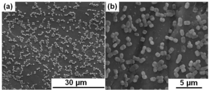
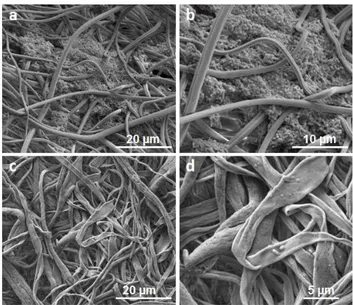
Figure 11: SEM micrographs of (a) PS and (b) PSU webs without bacterial
immobilization, and (c) STB5 immobilized PS and (d) STB5 immobilized PSU webs after 30 days of incubation for bacterial immobilization. (Copyright © 2013, Reproduced from Ref. [53] with permission from Springer)………...….36
Figure 12: Cr(VI) bioremoval profiles of (a) free STB5 cells at different pH
levels, (b) only STB5, STB5/PS and STB5/PSU samples at different initial Cr(VI) concentrations, (c) only STB5, only PS, only PSU, STB5/PS and STB5/PSU samples at an initial concentration of 25 mg/L. Error bars represent mean of three independent replicates. (Copyright © 2013, Reproduced from Ref. [53] with permission from Springer)……….………..38
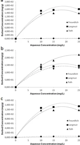
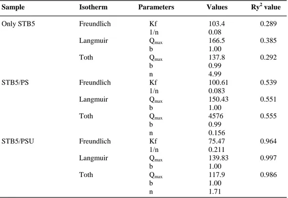
Figure 13: Adsorption isotherm plots of (a) only STB5, (b) STB5/PS, (c)
STB5/PSU samples for Freundlich, Langmuir and Toth adsorption models. (Copyright © 2013, Reproduced from Ref. [53] with permission from Springer)………..41
xv
Figure 14: Reusability and post-storage test results of STB5/PS and STB5/PSU
biocomposite webs for an initial concentration of 25 mg/L. Error bars represent mean of three independent replicates. (Copyright © 2013, Reproduced from Ref. [53] with permission from Springer)………...………43
Figure 15: SEM micrographs of STB5 immobilized (a-b) PS and (c-d) PSU
webs after the reusability tests, showing robust attachment of bacterial biofilms on fibrous surfaces at (a-c) 5000X and (b-d) 10000X magnification. (Copyright © 2013, Reproduced from Ref. [53] with permission from Springer)………....44
Figure 16: Photographs of pristine, bacteria immobilized and bacteria detached
nanofibers…
………...………
...51Figure 17: SEM micrographs of STB1 immobilized pCA nanofibers after 7
days of incubation at (a) 4000X and (b) 8000X; and bacteria detached pCA nanofibers at (c) 4000X and (d) 20000X magnification………...54
Figure 18: SEM micrographs of (a) A. calcoaceticus STB1 immobilized and (b) P. aeruginosa ATCC 47085 immobilized nCA nanofibers after 3 days of
incubation at 6000X; and bacteria detached CA nanofibers for (c) previously A.
calcoaceticus STB1 immobilized and (d) P. aeruginosa ATCC 47085
immobilized web samples at 5000X magnification………...………….56
Figure 19: (a) Schematic representation of electrospinning process for nCA and
pCA webs, and photographs of nCA and pCA webs, (b) representative images for bacteria immobilized webs including a SEM micrograph and schematic representation of bacterial cells on fibrous surfaces. (Copyright © 2013, Reproduced from Ref. [19] with permission from the Royal Society of Chemistry)………...64
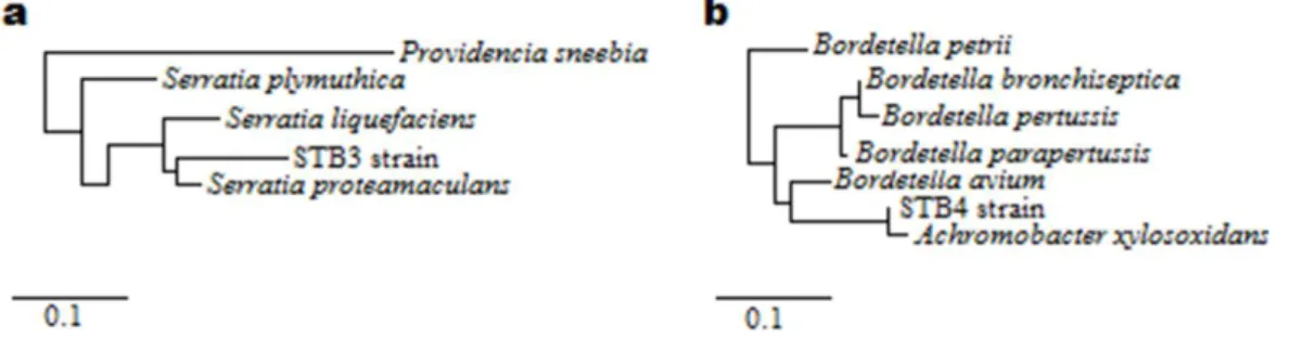
Figure 20: Phylogenetic trees of (a) STB3 and (b) STB4 strains according to
16S rRNA gene sequencing analysis. (Copyright © 2013, Reproduced from Ref. [19] with permission from the Royal Society of Chemistry)…………...…...71
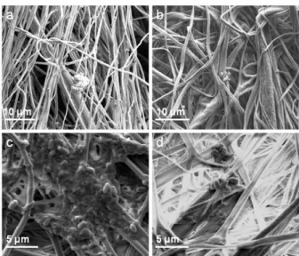
Figure 21: SEM micrographs of (a) pristine nCA and (b) pristine pCA webs.
Pores can be seen on a pCA nanofiber in the inlet figure. (Copyright © 2013, Reproduced from Ref. [19] with permission from the Royal Society of Chemistry)………..……….73
xvi
Figure 22: SEM micrographs of (a-c) nCA and (b-d) pCA nanofibers showing
immobilization of STB3 cells onto (a) nCA nanofibers and (b) pCA nanofibers; and immobilization of STB4 cells onto (c) nCA nanofibers and (d) pCA nanofibers after 7 days of incubation. (Copyright © 2013, Reproduced from Ref. [19] with permission from the Royal Society of Chemistry)……….…..…………..……...74
Figure 23: SEM micrographs of (a-c) nCA and (b-d) pCA nanofibers showing
immobilization of STB3 cells onto (a) nCA nanofibers and (b) pCA nanofibers; and immobilization of STB4 cells onto (c) nCA nanofibers and (d) pCA nanofibers after 21 days of incubation. (Copyright © 2013, Reproduced from Ref. [19] with permission from the Royal Society of Chemistry).……….……74
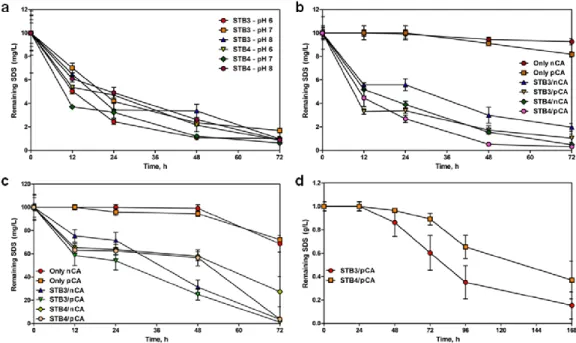
Figure 24: SDS biodegradation profiles of (a) STB3 and STB4 strains for
differential pH levels at 10 mg/L SDS, (b) pristine nCA, pristine pCA, STB3/nCA, STB3/pCA, STB4/nCA and STB4/pCA webs at 10 mg/L SDS, (c) pristine nCA, pristine pCA, STB3/nCA, STB3/pCA, STB4/nCA and STB4/pCA webs at 100 mg/L SDS and (d) STB3/pCA and STB4/pCA webs at 1 g/L SDS. Error bars represent mean of three independent replicates. (Copyright © 2013, Reproduced from Ref. [19] with permission from the Royal Society of Chemistry)………...78
Figure 25: LC-MS spectra of (a) SDS solution in water at 100 mg/L (b) nutrient
broth in water (c) STB3 sample having 100 mg/L initial SDS after incubation and suspension of bacterial cells (d) STB4 sample having 100 mg/L initial SDS after incubation and suspension of bacterial cells. (Copyright © 2013, Reproduced from Ref. [19] with permission from the Royal Society of Chemistry)……….………..……....83
Figure 26: Reusability test results of STB3/pCA and STB4/pCA webs for 5
cycles of SDS biodegradation at an initial concentration of 100 mg/L. Error bars represent mean of three independent replicates. (Copyright © 2013, Reproduced from Ref. [19] with permission from the Royal Society of Chemistry)….……84
xvii
Figure 27: SEM micrographs of (a-b) STB3 immobilized pCA webs and (c-d)
STB4 immobilized pCA webs after the reusability test, showing strong bacterial attachments. (Copyright © 2013, Reproduced from Ref. [19] with permission from the Royal Society of Chemistry)………...…...86
Figure 28: SEM micrographs of (a, e, i) aligned and no salt added PSU fibers,
(b, f, j) aligned and salt added PSU fibers (c, g, k) randomly oriented and no salt added PSU fibers (d, h, l) randomly oriented and salt added PSU fibers. (a-d) correspond to pristine PSU fibers, (e-h) correspond to bacteria immobilized PSU fibers after 7 days of incubation (i-l) correspond to bacteria immobilized PSU fibers after 21 days of incubation. As seen in the micrographs, addition of salt reduces the fiber diameters considerably……….………...97
Figure 29: VCC (Viable cell counting) assay results of aligned, aligned (with
salt), random, random (with salt) PSU fibers after 21 days of incubation period.…...98
Figure 30: MB and NH4+ removal profiles of free STB1 cells in a separate
system within 72 h of incubation. 50 mg/L of initial NH4+ was utilized as the
nitrogen source in MB removal experiments………..…………99
Figure 31: Simultaneous removal of MB and NH4+ by bacteria immobilized
PSU fibers at a constant initial MB concentration (25 mg/L) and varying initial NH4+ concentrations (25, 50, 100 mg/L) within 72 h of
incubation……….………….100
Figure 32: NH4+ and MB removal profiles of pristine PSU fibers within 72 h of
incubation.……….101
Figure 33: Reusability test results of bacteria immobilized PSU fibers in a five
consecutive cycle…..……….…102
Figure 34: Initial characterization of the three isolates (Enterococcus hermanniensis, Clavibacter michiganensis and Halomonas variabilis) for their
dye removal capabilities against Setazol Blue BRF-X (SBBX) and Setazol Turquoise Blue G (STBG) dyes at an initial concentration of 50 mg/L)…....113
xviii
Figure 35: Schematic representation of the electrospinning process and
representative images for bacterial immobilization including a photograph of bacteria immobilized electrospun nanofibrous web, a SEM micrograph of bacteria immobilized nanofibers and a schematic representation of the immobilized cells on electrospun nanofibers………...114
Figure 36: SEM micrographs of (a) pristine PCL (b) pristine PLA (c)
bacteria/PCL and (d) bacteria/PLA webs.…………...115
Figure 37: (a) Dye removal profiles of free-bacteria, pristine PCL web, pristine
PLA web, bacteria/PCL web and bacteria/PLA web samples at initial concentrations of 50, 100 and 200 mg/L. Error bars represent mean of three independent replicates.……….…….117
Figure 38: Reusability test results of bacteria/PCL and bacteria/PLA webs at an
initial dye concentration of 100 mg/L. Error bars represent mean of three independent replicates………..………….121
Figure 39: Comparison for OD600 values of bacteria/PCL and bacteria/PLA
webs before and after the reusability test………..121
Figure 40: SEM micrographs of (a) bacteria/PCL and (b) bacteria/PLA webs
after the reusability test..………...…122
Figure 41: (a) Schematic representation of electrospinning process for bacteria
encapsulated PVA and PEO webs, and photographs of PVA and PEO webs, (b) representative images for bacteria encapsulated webs including a SEM micrograph and a schematic representation of a bacterial cell inside PVA/PEO fibers.……….134
Figure 42: SEM micrographs of (a) pristine PVA (b) pristine PEO (c)
bacteria/PVA (d) bacteria/PEO webs and fluorescence microscopy images of (e) bacteria/PVA and (f) bacteria/PEO webs………..135
Figure 43: Raman spectra of (a) pristine PVA and bacteria/PVA and (b) pristine
PEO and bacteria/PEO webs.………136
Figure 44: Growth profiles of bacterial cells which have grown in polymer-free
LB medium, PVA containing LB medium or PEO containing LB medium within 18 h. Error bars represent mean of three independent replicates.……….138
xix
Figure 45: (a) MB removal profiles of free-bacteria, bacteria/PVA web and
bacteria/PEO web samples at initial concentrations of 10, 15 and 25 mg/L. (b) Concentration vs. time graph of free-bacteria, bacteria/PVA web, bacteria/PEO web, pristine PVA web and pristine PEO web samples at 15 mg/L of initial MB. Error bars represent mean of three independent replicates………...139
Figure 46: Growth profiles of bacterial cells which have grown in polymer-free
LB medium, PVA containing LB medium or PEO containing LB medium within 18 h. Error bars represent mean of three independent replicates.……….139
Figure 47: Viable cell counting (VCC) results of bacteria/PVA and
bacteria/PEO web samples for storage at (a) 4 oC for 3 months and (b) 25 oC for 10 days………...145
LIST OF TABLES
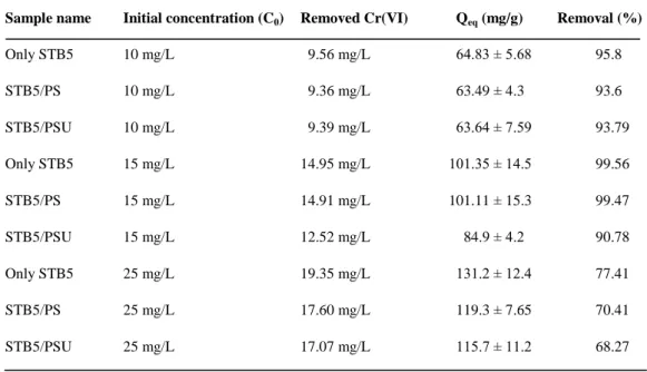
Table 1. Removal capacities of only STB5, STB5/PS and STB5/PSU samples at
equilibrium under different initial Cr(VI) concentrations, measured at the end of the 72 h removal period. T = 30 oC, agitation rate: 150 rpm, average bacterial biomass concentration 0.15 ± 0.03 g/L. (Copyright © 2013, Reproduced from Ref. [53] with permission from Springer)………...…39
Table 2. Adsorption isotherm coefficients of only STB5, STB5/PS and
STB5/PSU samples for each isotherm model. (Copyright © 2013, Reproduced from Ref. [53] with permission from Springer)………...42
Table 3. The R2 values of zero, first, second and third order plots for the removal of Cr(VI) by only STB5, STB5/PS and STB5/PSU samples. (Copyright © 2013, Reproduced from Ref. [53] with permission from Springer)…………42
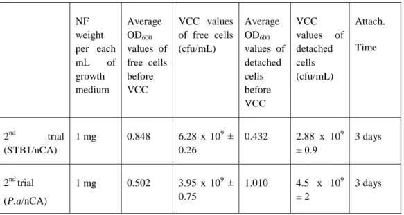
Table 4. Comparison of VCC values of free and detached STB1 cells (n=4,
S.E.M).………...….54
Table 5. Comparison of VCC values of free and detached bacterial cells (n=4,
xx
Table 6. Comparison of VCC values of sonicated and non-sonicated free
bacterial cells (n=3, S.E.M)………..………...…59
Table 7. Viable cell counting (VCC) results of STB3/nCA, STB3/pCA,
STB4/nCA and STB4/pCA webs at different time periods. The results are presented in cfu/mL. The w/v ratio of each web that was utilized for the detachment process was equal (0.5 mg/mL). (Copyright © 2013, Reproduced from Ref. [19] with permission from the Royal Society of Chemistry)………...………75
Table 8. Degradation capacities of free STB3 and STB4 cells, and STB3/nCA,
STB3/pCA, STB4/nCA, STB4/pCA webs at equilibrium at the end of the degradation period. T = 30 ◦C, agitation rate: 180 rpm. (Copyright © 2013, Reproduced from Ref. [19] with permission from the Royal Society of Chemistry)…...…79
Table 9. Adsorption kinetics coefficients of STB3/pCA and STB4/pCA webs
for each isotherm model. (Copyright © 2013, Reproduced from Ref. [19] with permission from the Royal Society of Chemistry)……….80
Table 10. The R2 values of zero, first, second and third order plots for the removal of SDS by STB3/pCA and STB4/pCA webs………..81
Table 11. Removal capacities of free-bacteria, bacteria/PCL web and
bacteria/PLA web samples at equilibrium at the end of the removal process. T = 30 oC, agitation rate: 150 rpm, incubation time: 48 h……….…116
Table 12. Adsorption isotherm coefficients of free-bacteria, bacteria/PCL web
and bacteria/PLA web samples for each isotherm model………119
Table 13. The R2 values of zero, first, second and third order plots for the dye removal by free-bacteria, bacteria/PCL web and bacteria/PLA web samples………..…119
Table 14. Removal capacities of free-bacteria, bacteria/PVA web and
bacteria/PEO web samples at equilibrium at the end of the removal process. T = 30 oC, agitation rate: 125 rpm, incubation time: 48 h……….140
Table 15. Adsorption isotherm coefficients of free-bacteria, bacteria/PVA web
xxi
Table 16. The R2 values of zero, first, second and third order plots for the removal of MB by free-bacteria, bacteria/PVA web and bacteria/PEO web samples……….……….143
Table 17. Viable cell counting (VCC) results of bacteria/PVA and bacteria/PEO
web samples after storing at 4 oC or 25 oC for different time periods. The results are presented in cfu/mL. The w/v ratio of each web that was utilized for the VCC assay was equal (5 mg/mL)………...……...145
1
Chapter 1
2
1. Water pollution and sustainable water management
Water is the main component of life and its role in international affairs has become of great importance. Although earth has tremendous amounts of water sources, its distribution and availability is the major issue for regular use. Insufficient amount of water sources can lead to drought, famine and health problems. Because of that, water sustainability is a major issue even in water-rich countries, and novel strategies have being developed for sustainable water use.
One of the main area of use for water is in industrial processes. For various operations, water is extensively used and recycling is not in charge for many of them, so that, industrial wastewater releases as effluent to natural water sources (e.g. river, sea) at the end. Although for some wastewater (e.g. food industry), most of the contaminants are highly biodegradable and not harmful for biological organisms, for some of the others (e.g. textile industry), the concentrations of contaminants should be strictly regulated and must be removed before discharge.
In addition to industrial wastewater, domestic wastewater (greywater) needs to be remediated before discharge to natural water sources. Even though this type of wastewater is not generally as harmful as industrial wastewater, because of the potential toxicity of cleaning agents (e.g. detergents, shampoos), it should be properly remediated as well. Cleaning agents may contain various chemicals as ingredients for different purposes. Nevertheless, the toxicity problem is mainly due to the presence of surface active agents (surfactants) in
3
their formula, hence more biodegradable surfactants are preferred for easier remediation of water sources from surfactants. Because of the biodegradability issue, most of the current cleaning agents contain LAS (Linear Alkyl Sulphonate) type of surfactants, which are relatively more biodegradable than old-fashion ABS (Alkyl Benzene Sulphonate) type of surfactants [1].
Figure 1: Foaming in an industrial effluent due to contamination of surfactants.
Today, chemical, physical and biological methods are used for remediation of water systems from contaminants. Some of these methods are used in combination to obtain the highest efficiency. For last decades, bio-based methods have received more attraction because of their eco-friendliness, cost-effectiveness and sustainability. Furthermore, bio-based methods are open for improvement since many types of microorganisms can be used for these purposes, and genetic or material engineering can be performed for improved bioremediation capability or development of bio-hybrid materials. By
4
integration of specific microorganisms or enzymes with carrier materials, bio-hybrid materials can be generated for intended uses. These types of materials can be more effective than separate systems and can bring some advantages (e.g. reusability).
2. Bio-based approaches for water sustainability
Bio-based approaches have being used for remediation of water systems as alternatives to physical/chemical treatment methods. These approaches are suggested to be more eco-friendly and sustainable for water treatment. Some biotechnology companies market specific bacterial solutions as commercial products for wastewater treatment. Dead or alive biomasses have being used for removal of different contaminants, which may include bacteria, fungi, yeast, agricultural waste and microalgae. These biomasses can remediate water pollutants either by biosorption or bioaccumulation. Although dead biomasses can only be used for biosorption, living cells can possess both bioaccumulation and biosorption, hence higher efficiency for bioremediation could be achieved by living cells in some studies [2]. Some plant species can be used for water cleaning purposes as well, known as phytoremediation, and it can be very effective strategy in some cases. Relatively few numbers of plant species have being used for this purpose and discovery of novel more efficient plant species can make this strategy more favorable for remediation of water systems.
In general, microorganisms in nature do not encounter with water contaminants, so they may have difficulties to remediate them without prior adaptations. Nonetheless, after they encounter with these contaminants, they
5
may develop new strategies to deal with and survive. By applying genetic engineering techniques, some microorganisms can gain bioremediation capability for certain contaminants or their existing bioremediation capabilities can be enhanced. Using special bacteria for water treatment is both more effective and faster than other methods in some cases. Furthermore, bacteria production and growth is very economical in comparison to other methods. The issues that should be considered before use of bioremediating bacteria for remediation purposes are: growth rate, pathogenicity and rate of metabolism. Bacterial cells should not be pathogenic for use in remediation applications for prevention of potential diseases. Although some bacteria can be used as dead biomass for adsorption purposes, for continuous activity and remediation of more complex contaminants, biodegradation or bioconversion are needed. Dead cell biomasses can be used for heavy metal removal (e.g. hexavalent chromium removal), yet they are not so effective for removal of more complex pollutants such as textile dyes and surfactants.
There are numerous examples in the literature which present specific microorganisms that have tolerance to grow in extreme environments and having bioremediation capability for a specific contaminant. Besides using those microorganisms planktonic in a liquid medium, they can also be used as immobilized on a carrier material, for a specific application. Integration of bioremediating microorganisms to a carrier material makes the final product potentially reusable, more resistant to environmental extremes and more practical. The carrier materials for bio-integration are selected for their biocompatibility, availability, cost-effectiveness and potential biodegradability.
6
The carrier systems should be non-toxic for biological organisms during and after application. After the end of application, they should be easily recycled.
3. Electrospun fibrous networks as carrier matrices for
development of biointegrated systems
In today’s world, different types of microorganisms are in use for biotechnological purposes and bioremediation is one of the most common application areas. By the developments in biotechnology field, novel microorganisms have been isolated for treatment of water pollutants. Besides using these microorganisms in a freely floating form, microorganisms can be integrated on a carrier material and their integration makes those carrier materials functional for specific purposes. Biotechnological applications of bio-integrated hybrid systems can be more advantageous than planktonic cells in terms of lower space and growth medium requirements, ease of application and potential reusability of the system. In addition, it may also be advantageous for the resistance of cells to harsh environmental conditions. For instance, for water purification in aquaculture systems, bacteria integrated sand or pebbles can be used for continuous remediation of nitrogenous wastes in the environment.
Electrospun nanofibers are suitable materials for wastewater filtration (detoxification, decoloring, purification etc.) and by different types of modifications, their availability for environmental applications can be augmented. In addition to morphological modifications of electrospun nanofibers, functionalization of those nanofibers with various molecules and microorganisms makes them more available for environmental applications. In
7
recent years, electrospun fibrous materials have become available candidates as carrier systems for specific microorganisms, since electrospinning is an easy and economical production technique to produce tuneable nanoscale fibrous materials with unique physical/chemical properties.
Figure 2: Schematic representation of the electrospinning set-up.
8
There are some pioneer studies in the literature about integration of different microorganisms to electrospun nanofibers. There are several ways to integrate microorganisms to nanofiber structures, which are: direct encapsulation of microorganisms to nanofiber structures [3-9], encapsulation of microorganisms to core-shell structures [10-13] and physical/chemical attachment of microorganisms to nanofiber surfaces [14-22]. Most of the studies consist of survival and proliferation profiles of the integrated microorganisms, but the number of studies related with the application of those biointegrated nanofibers are very few in the literature.
Electrospun nanofibers have various advantages over other carrier materials such as activated carbon and paper discs. For instance, high surface to volume ratio, porosity and biocompatibility make electrospun nanofibers as ideal carrier materials for the attachment of microorganisms. Since electrospun nanofibers can be produced from different mixtures, they can be produced with desired properties and morphologies for the attachment of different types of microorganisms. In addition, by using encapsulation strategies (direct or core-shell), microorganisms can be encapsulated within electrospun fibrous webs, without a need for post processing step. These systems can be very useful for long term storage, and provide ease of handling and lower space requirements.
9
Chapter 2
Bacteria immobilized electrospun cellulose
acetate fibrous webs for ammonium removal
(Parts of this study was published as “Efficient ammonium removal from aquatic environments by Acinetobacter calcoaceticus STB1 immobilized on an electrospun cellulose acetate nanofibrous web”, Omer Faruk Sarioglu, Asli Celebioglu, Tamer Uyar and Turgay Tekinay, Green Chemistry, July 9, 2013 (Web), Reproduced (or 'Reproduced in part') from Ref. [18] with permission from the Royal Society of Chemistry. doi:10.1039/c3gc40885)
10
1. Introduction
Ammonium (NH4+), nitrite (NO2−) and nitrate (NO3−) comprise the most
common nitrogenous compounds found naturally in aquatic ecosystems, and are formed by atmospheric decomposition, degradation of organic matter, and N2
fixation by certain microorganisms [23]. However, human activities have altered the nitrogen content of aquatic environments for the last two centuries, and the accumulated nitrogenous wastes now have a significant effect on the ecosystem [23]. Among the nitrogenous pollutants released to aquatic environments, ammonia is one of the most toxic ones and exists in water as either non-dissociated ammonia (NH3) or the ammonium ion (NH4+) [24, 25]. Ammonia
concentrations between 2 and 10 mg/L are lethal for many aquatic organisms, and concentrations greater than 1.5 mg/L are considered unacceptable in drinking water by the U. S. Environmental Protection Agency (US EPA) [25]. The main metabolic by-products of ammonia are NO2- and NO3-, both of which
are also toxic for aquatic life. US EPA regulations dictate that the concentrations of nitrite and nitrate in drinking water should not exceed 1 mg/L and 10 mg/L respectively, and the sum of nitrite and nitrate concentrations should be lower than 10 mg/L [26]. Therefore, remediation of high ammonium and nitrogen concentrations in aquatic systems is necessary to maintain the quality of water for human or agricultural use. Conventional wastewater treatment systems include biological applications with both autotrophic nitrifiers and heterotrophic denitrifiers in dynamic aerobic and anaerobic conditions [27]. However, heterotrophic ammonium removal by a single nitrifier/denitrifier strain has many
11
advantages, such as the simultaneous processing of nitrification and denitrification reactions at equivalent conditions, and novel bacterial species have been isolated from different aquatic environments for that purpose [27-29]. Electrospinning is an emerging nanofiber/nanoweb production technique and has attracted much attention over the past decade due to its simplicity, versatility and cost-effectiveness [30-32]. Electrospun nanofibers and their nanofibrous webs display a variety of unique properties, such as large surface-to-volume ratios and highly porous structures, allowing their use as effective matrices in membranes and filters for environmental applications [30-35]. For instance, the use of immobilized microorganisms on electrospun nanofibrous polymeric mats was recently shown to increase the rate of nitrate removal [14]. In that study, microalgal cells were effectively immobilized on electrospun chitosan nanofiber mats in order to generate a hybrid system for nitrate removal [14]. Nitrate removal by nanofiber-immobilized microorganisms has several advantages over the use of free cells in suspension, including lower space and growth medium requirements, ease of handling, and potential reusability of the same matrix over several treatment cycles [14]. Furthermore, immobilization of bacterial cells on polymeric network systems makes them more resistant to harsh environmental conditions, such as metal toxicity or extremes of salinity, temperature and pH [36]. Covalent coupling, cross-linking, physical entrapment and the natural process of bacterial adhesion can be used for the immobilization of microorganisms to nanofiber networks [37]. Natural adhesion is the most advantageous among these methods, as it enables the formation of biofilms
12
following surface attachment and results in maximal cell viability and biochemical activity [30].
It was previously shown that Acinetobacter calcoaceticus STB1 could remove high concentrations of ammonium at heterotrophic conditions [29]. This strain can successfully remove high concentrations of ammonium in several days, and is non-toxic for aquatic life, hence it can effectively be used for the remediation of aquatic environments.
In the current study, A. calcoaceticus STB1 cells were immobilized on electrospun cellulose acetate (CA) nanofibrous web in order to achieve enhanced ammonium removal in aquatic environments. CA was chosen as the fibrous matrix, as it is the most common used regenerative cellulose, and is biodegradable and biocompatible, which renders it advantageous in biological applications [38]. Electrospun CA nanofibers have been used for filtration, drug delivery, enzyme immobilization, artificial tissue matrix formation [39-42], and successful growth of fibroblasts and Schwann cells on CA nanowebs have been reported in the literature [43, 44]. Moreover, CA nanofibers can be converted into more functional and applicable forms by the incorporation of other polymers into the nanofiber mesh, or by the chemical conversion of cellulose into a variety of derivative fibers [45, 46]. Here, we successfully produced a nanofibrous biocomposite web by immobilizing STB1 cells on electrospun CA nanofibers for the removal of ammonium in aqueous systems. Reusability test results indicate that STB1/CA nanofibrous webs can be reused without significant loss of their ammonium removal capacity.
13
2. Experimental
2.1. Preparation of porous CA nanofibers
The electrospinning of cellulose acetate (CA) nanofibers was performed as detailed in a previous study [47]. While production of porous CA nanofibers generally requires post-treatment of the ultimate nanofiber structure, the porous CA nanofibers described here were produced from a dichloromethane (DCM)\acetone binary solvent system without additional treatment [47]. Constituent solvents of the DCM/acetone binary system were purchased from Sigma-Aldrich (USA) and used without any purification (dichloromethane, DCM, ≥99% (GC); acetone, ≥99% (GC); cellulose acetate, CA, Mw: 30000, 39.8 wt. % acetyl). Briefly, the homogenous electrospinning solution was prepared by dissolving CA in a DCM/acetone (2/1 (v/v)) binary solvent mixture at a 7.5% (w/v) polymer concentration. The clear CA solution was then placed in a 3 mL syringe fitted with a metallic needle of a 0.6 mm inner diameter. The syringe was fixed horizontally on the syringe pump (model SP 101IZ, WPI, USA). The electrode of the high-voltage power supply (Matsusada Precision, AU Series, Japan) was clamped to the metal needle tip, and the cylindrical aluminum collector was grounded. Electrospinning parameters were adjusted as follows: feed rate of solutions = 1 mL/h, applied voltage = 15 kV, tip-to-collector distance = 10 cm. Electrospun nanofibers were deposited on a grounded stationary cylindrical metal collector covered with aluminum foil. The electrospinning apparatus was enclosed in a Plexiglas box, and electrospinning was carried out at 25 oC at 24% relative humidity. Collected
14
nanofibers/nanowebs were dried overnight at room temperature under the fume hood. The process is summarized in Fig. 4.
Figure 4: (a) Schematic representation of electrospinning process for CA
nanofibers and photograph of CA nanofibrous web (b) photograph of STB1 immobilized CA nanofibrous web and schematic representation of bacterial cells on nanofiber surfaces. (Copyright © 2013, Reproduced from Ref. [18] with permission from the Royal Society of Chemistry)
2.2. Growth and immobilization of Acinetobacter calcoaceticus
STB1
The bacterial strain utilized in this study was isolated from brackish water samples collected from a commercial sea bass farm [29]. Immobilization of bacteria was achieved by the inclusion of CA nanofibrous webs in the growth
15
media of newly inoculated bacteria. Colonies were maintained in 100 mL culture flasks for 30-35 days. The ingredients of the growth medium were: 6.3 g/L Na2HPO4 (≥ 99%), 3 g/L KH2PO4 (≥ 99%), 0.5 g/L NaCl (≥ 99.5%), 2 g/L
glucose (anhydrous), and 300 mL/L of a trace elements solution consisting of 6.1 g/L MgSO4 (≥ 99.5%), 3 g/L H3BO3 (≥ 99.5%), 0.5 g/L MnCl2 (≥ 99%),
0.05 g/L CaCl2 (≥ 93%), 0.03 g/L FeSO4.7H2O (≥ 99%), 0.03 g/L CuCl2 (≥
97%), 0.03 g/L ZnCl2 (≥ 99.99%). Ammonium (in the form of NH4Cl, ≥ 99.5%)
was utilized as the nitrogen source during incubation and immobilization, with an initial concentration of 50 mg/L. Following the incubation period, bacterial immobilization was confirmed by SEM imaging and nanofiber samples of equal weights were prepared for further testing. All reagents utilized in this study were purchased from Sigma-Aldrich (USA).
2.3. Ammonium removal experiments by using STB1
immobilized CA nanofibers
The same basal growth medium utilized in bacterial immobilization studies was used in the heterotrophic ammonium removal experiments. Basal growth medium samples were spiked with varying amounts of ammonium (as NH4Cl),
inoculated with free bacterial samples, free nanofibers or bacteria-immobilized nanofibers and incubated for 48 h at 140 rpm and 30 °C. The positive control contained only bacterial inocula at an initial ammonium concentration of 50 mg/L, the negative control contained only nanofibers (0.4 mg of nanofiber per mL) at an initial ammonium concentration of 50 mg/L, and the experimental samples contained bacteria immobilized on CA nanofibers (0.4
16
mg of nanofiber per mL) at initial ammonium concentrations of 50, 100 and 200 mg/L. Initial ammonium values of the experimental samples were adjusted to 50, 100 and 200 mg/L to represent low, medium and high concentrations of ammonium, and to determine ammonium removal efficiencies at different concentration ranges. Samples were collected periodically to analyze ammonium, nitrite and nitrate values. Bacterial growth rates of the positive control samples were followed by OD600 measurements. Changes in ammonium,
nitrite and nitrate concentrations in the samples were determined by spectrophotometric test kits (Merck Ammonium Cell Test 14559, Merck Nitrate Cell Test 14563 and Merck Nitrite Cell Test 14547). Before performing the tests, samples were centrifuged for 1 min at 12000 rpm at room temperature, and the supernatants were used in analytical measurements of ammonium, nitrite and nitrate. All tests were done in triplicate. Experiments were repeated at least twice.
2.4. Scanning Electron Microscopy (SEM)
Millimeter-length nanofiber pieces with and without bacterial immobilization were cut and prepared for SEM analysis to monitor bacterial attachment before and after ammonium removal experiments. A protocol similar to the Greif and colleagues’ was utilized for sample fixation [48]. Briefly, samples were washed twice with PBS buffer and fixed by overnight incubation in 2.5% glutaraldehyde in PBS buffer at room temperature. Following gluteraldehyde fixation, samples were washed twice by PBS buffer and then dehydrated by immersion in a series of ethanol-water solutions ranging from 30% to 96%. Prior to SEM imaging, all
17
samples were coated with a 5 nm layer of gold-palladium. A Quanta 200 FEG scanning electron microscope (FEI Instruments, USA) was used for the acquisition of SEM images.
2.5. Reusability test for STB1 immobilized CA nanofibrous web
Ammonium removal studies were performed 5 times to assess the reusability of the bacteria-immobilized nanofibers. Prior to each cycle, nanofiber pieces were washed twice with PBS buffer and incubated overnight in PBS to remove any unattached bacteria. The ammonium removal experiments (incubation at 140 rpm and 30 oC for 48 h) described above were performed after each washing step, for a total of 5 cycles. The initial ammonium concentration was fixed at 100 mg/L, since this concentration was found to be more suitable to observe changes in performance values in each cycle compared to low (50 mg/L) and high (100 mg/ L) initial ammonium concentrations. Ammonium concentrations were measured at 0 h and 48 h, and the percentage removal of ammonium was calculated using these results. Each cycle was terminated after 48 h of total incubation and washing steps were repeated for nanofiber samples before the initiation of the next cycle. All tests were done in triplicate.
3. Results and Discussion
3.1. Attachment of STB1 strain on CA nanofibrous web
CA nanofibers can be obtained in smooth or porous morphology depending on the solvent type utilized. While the N,N-dimethylacetamide (DMAc)/acetone blend is one of the most common solvent systems for the electrospinning of
18
uniform and smooth CA nanofibers [49], we have previously demonstrated the production of nanoporous CA nanofibers by using a highly volatile DCM/acetone solvent mixture [47]. While conventional electrospun CA nanofibers are already suitable for use in biological systems; the rough surface and the higher surface area of porous electrospun CA nanofibers were expected to increase the utility of CA nanowebs in biological applications, and especially for biomedical research. SEM imaging was performed to observe the bacterial adhesion to nanofibers, and 30 days were found to be required for the robust attachment of bacteria onto nanofiber surfaces. Fig. 5a and Fig. 5b show
Acinetobacter calcoacetius STB1 cells after 7 days of incubation, wherein no
biofilm formation can be observed. SEM images of porous CA nanofibers prior to bacterial attachment are depicted in Fig. 6a and Fig. 6b. The CA fiber diameter range was between 500 nm and 1.5 μm, and the fibers had a ribbon-like morphology [47]. Fig. 6c and Fig. 6d show bacteria strongly attached onto nanofibrous web after 35 days of incubation, and the attached bacteria are observed to form a biofilm structure by adhering to each other and surrounding the filaments of the CA web. This type of attachment was found to be adequate for further studies, and ammonium removal experiments were started with STB1 immobilized CA web samples at this stage.
19
Figure 5: General morphology of Acinetobacter calcoaceticus STB1 under
Scanning Electron Microscope (SEM) at 5000X (a) and 15000X (b) magnification. (Copyright © 2013, Reproduced from Ref. [18] with permission from the Royal Society of Chemistry)
Figure 6: SEM micrographs of bacteria-free electrospun CA nanofibers at (a)
2500X and (b) 200000X; and STB1 immobilized nanofibers after 35 days of incubation at (c) 5000X and (d)10000X magnification. (Copyright © 2013, Reproduced from Ref. [18] with permission from the Royal Society of Chemistry)
20
3.2. Ammonium removal capability of STB1 immobilized CA
nanofibrous web
STB1 immobilized CA nanofibrous webs have shown efficient removal of ammonium at each concentration within 48 h, and the percentile ammonium removal capability of the web samples decreased as the initial ammonium concentrations increased (Fig. 7c, Fig. 7d, Fig. 7e). Bacteria-free CA webs displayed negligible decreases in ammonium concentrations (Fig. 7b), and the removal capability of STB1 immobilized CA nanofibrous web samples were therefore attributed to bacterial nitrogen metabolism. Ammonium removal capability of the STB1/CA nanofibrous web is very similar to that of the free bacteria sample at the initial ammonium concentration of 50 mg/L (Fig. 7a and Fig. 7c), which shows that the STB1/CA nanofibrous web can provide the same outcome as free-suspended bacteria at a defined w/v ratio without including any additional bacterial inocula into the aquatic system. The STB1/CA nanofibrous web was capable of fully remediating an initial ammonium concentration of 50 mg/L, and displayed 98.5% and 72% removal rates at initial ammonium concentrations of 100 mg/L and 200 mg/L, respectively. Increase in nitrate and nitrite concentrations were limited, nitrite concentrations in particular were below detectable limits. Increase in nitrate concentrations was likewise minimal, not exceeding 2 mg/L at the end of 48 h period for each sample. As such, concentrations of nitrite, nitrate and their sum were all below the legal limits for water quality managements [25], which suggests that the production of toxic
21
metabolic by-products of ammonium is not a problematic issue for STB1/CA nanofibrous webs.
Figure 7: Ammonium, nitrite and nitrate levels for: (a) free STB1 cells at initial
ammonium concentration of 50 mg/L; (b) bacteria-free CA web at initial ammonium concentration of 50 mg/L; (c) STB1 immobilized CA web at initial ammonium concentration of 50 mg/L; (d) STB1 immobilized CA web at initial ammonium concentration of 100 mg/L; (e) STB1 immobilized CA web at initial ammonium concentration of 200 mg/L. Error bars represent mean of three independent replicates. (Copyright © 2013, Reproduced from Ref. [18] with permission from the Royal Society of Chemistry)
22
Since nitrite and nitrate levels were minimal for STB1, we have tried to account for the remaining products of ammonium remediation in a previous study by performing Total Nitrogen (TN) analysis with an elemental analyzer [29]. The only nitrogen source in the bacterial growth medium was ammonium for STB1 cells, hence we were able to determine the percentage of ammonium incorporated into cellular biomass for the 100 mg/L sample. Around 22% of the initial ammonium concentration was found to be introduced into the cell biomass; and a further 4% was initially incorporated into cell biomass and subsequently released to the supernatant. For this reason, we have concluded that STB1 cells converted most of the remaining ammonium into gaseous denitrification products [29]. A similar situation was previously observed by Zhao and colleagues, who demonstrated that Acinetobacter calcoaceticus strain HNR could convert a considerable amount of ammonium into N2 gas [27].
3.3. Reusability and applicability of STB1 immobilized CA
nanofibers
Ammonium removal capabilities of reused STB1 immobilized CA nanofibrous webs were tested for five cycles of reuse. Fig. 8 shows the performance values of each cycle for the total of 5 cycles. 86% of ammonium removal capacity was obtained for the final cycle (5th cycle) which suggests STB1/CA nanofibrous webs can sustain their ammonium removal capacity under several cycles of reuse. This result is highly promising and with a successful optimization, STB1/CA nanofibrous web may be utilized repeatedly
23
for ammonium remediation, constituting a reusable material for ammonium remediation from aquatic environments.
Figure 8: Reusability test results of STB1 immobilized CA web for 5 cycles of
ammonium removal experiments at initial ammonium concentration of 100 mg/L. Error bars represent mean of three independent replicates. (Copyright © 2013, Reproduced from Ref. [18] with permission from the Royal Society of Chemistry)
After the reusability experiments, CA webs were washed several times with PBS and fixed for SEM imaging. Fig. 9a and Fig. 9b show visible bacterial biofilms on nanofiber surfaces, suggesting that STB1 cells displayed a stronger attachment to CA webs compared to the beginning of the reusability test. As such, washing and reuse of these webs did not lead to a decrease in the quantity of bacterial biofilms, in contrast, the extent of biofilm formation increased and a stronger attachment to the nanofibrous matrix was observed.
24
Figure 9: SEM micrographs of STB1 immobilized CA web after the reusability
tests, showing robust attachment of bacterial biofilms on nanofiber surfaces at (a) 2500X and (b) 10000X magnification. (Copyright © 2013, Reproduced from Ref. [18] with permission from the Royal Society of Chemistry)
The remediation of aquatic systems is an important issue and sustainable solutions, particularly novel and green approaches, for the removal of a wide host of pollutants have received considerable attention in recent times [50, 51]. Since our bacterial isolate is not pathogenic or toxic [29], and biological treatment methods are generally more sustainable and environmentally friendly than their physical and chemical equivalents [52], the use of our bacterial strain is advantageous for ammonium removal. In this study, we immobilized STB1 bacterial strain on electrospun CA nanofibrous webs to analyze the efficiency of these bacteria in ammonium removal, which would be of considerable use in developing novel commercial removal techniques. We deem this approach is successful since bacteria could attach strongly on nanofiber surfaces, STB1 immobilized CA nanofibrous webs could remediate ammonium as effectively as freely floating STB1 bacterial inocula, and the biocomposite material could be used for several cycles for ammonium removal, as shown by reusability test results (Fig. 8). Similar approaches have been proposed in the literature. Eroglu et al. have immobilized microalgal cells on electrospun chitosan nanofiber mats
25
for the removal of nitrate from liquid effluents [31]. In the present study, ammonium was chosen as the target contaminant due to its high toxicity, and different concentration ranges of ammonium were tested to determine the efficiency of bacteria-immobilized nanofibrous web samples for ammonium removal. The time required for complete removal of 100 mg/L ammonium by STB/CA nanofibrous webs was around 48 h. Zhao et al. reported an
Acinetobacter calcoaceticus strain capable of completely removing 120/mg L of
initial ammonium within 48 h, albeit without the immobilization of bacterial cells on a solid material, which is very similar to our results [26]. The time required for complete removal can be reduced by further modifications, such as increasing the number of bacterial biofilms on nanofiber surfaces or performing optimization studies in heterotrophic conditions for enhanced nitrogen metabolism. However, the presence of embedded bacterial cells within the biofilm complex prevents the estimation of total bacterial count on nanofiber surfaces, and it is therefore difficult to make a quantitative comparison between our results and previous reports in terms of the number of bacteria required for a defined ammonium removal rate.
We observed that, the results of freely floating STB1 cells and STB1 immobilized CA nanofibrous web are quite close however, using STB1/CA nanofibrous web is more advantageous in terms of several points. While a small portion of STB1 immobilized CA nanofibrous web is enough for ammonium bioremoval in a liquid environment, there should be a sufficient number of unimmobilized bacteria in its growth medium for removal of ammonium. STB1/CA nanofibrous web is more applicable and more cost-effective as well,
26
since when we compare the required amount of STB1/CA nanofibrous web and free STB1 cells for removal of a defined concentration of ammonium, the weight of required STB1/CA nanofibrous web is much lighter in comparison to free STB1 cells (0.4 g of STB1 immobilized CA web is equivalent to 1 L of bacteria containing liquid medium to show the same performance), which provides ease of application for large scale environments and lower transportation costs. In addition, since free STB1 cells are dispersed throughout the medium, it is much more difficult to isolate and reuse them in another ammonium-contaminated area. Finally, biofilm formation in STB1/CA nanofibrous web brings some advantages over free STB1 cells such as higher resistance to environmental extremes and enhanced metabolic activity. Thus, although the results of STB1/CA nanofibrous web and free STB1 cells are very close, the former one is more advantageous for ammonium removal due to aforementioned reasons.
In brief, ammonium removal by STB1 immobilized CA nanofibrous web is very effective and easily applicable to be utilized in a wide variety of environments. The novel biocomposite material described in the present study may therefore assist in the development of alternative green strategies for effective ammonium removal in a variety of freshwater and possibly marine environments.
27
Chapter 3
Bacteria immobilized electrospun fibrous
webs for hexavalent chromium remediation
(Parts of this study was published as “Bacteria-immobilized electrospun fibrous polymeric webs for hexavalent chromium remediation in water”, Omer Faruk Sarioglu, Asli Celebioglu, Turgay Tekinay and Tamer Uyar, International
Journal of Environmental Science and Technology, June 2, 2016 (Web),
Reproduced (or 'Reproduced in part') from Ref. [53] with permission from Springer. doi:10.1007/s13762-016-1033-0)
28
1. Introduction
Chromium is a commercially important metallic element that is integral for many important industrial processes, such as electroplating, steel production, leather tanning, textile manufacturing and chromate preparation [54]. The trivalent (Cr(III)) and hexavalent (Cr(VI)) forms are the most commonly encountered forms in nature [55]. While Cr(III) is not transported into cells and can be tolerated by many organisms at moderate concentrations, Cr(VI) is a toxic and carcinogenic form that readily permeates through biological membranes and may disrupt the functions of intracellular proteins and nucleic acids [56]. Chromium has been designated as a major pollutant by the United States Environmental Protection Agency (US EPA), and the legal limit defined for all forms of chromium, including Cr(VI), in drinking water is 0.1 mg/L [57]. Heavy metal contamination in water systems can be treated by physical or chemical treatment methods (e.g. chemical oxidation or reduction, ion exchange, reverse osmosis [58]. However, there are several problems related with these techniques such as high operating and maintenance costs, high energy requirements, operational complexity and the production of secondary waste products [59]. Today, biological treatment methods have received considerable attention as potential alternatives to conventional treatment methods [59-61]. In general, bioremediation of heavy metals is performed under acidic pH, since the existence of excess hydrogen ions in the medium facilitates the reduction of metal cations, resulting in higher removal efficiencies [62]. However, these are not self-sustaining and require the constant influx of externally produced