Bandwidth Improvement in a cMUT Array with
Mixed Sized Elements
Can Bayram, Selim Olcum, Muhammed N. Senlik, and Abdullah Atalar
Department of Electrical EngineeringBilkent University Ankara, Turkey
Email: [email protected]
Abstract— A capacitive micromachined ultrasonic transducer
(cMUT) is typically fabricated by concatenation of several cMUT cells with identical physical dimensions. If the membrane thick-ness is kept fixed, the radius of the cMUT determines the center frequency of operation. A smaller radius implies a greater center frequency. Therefore, it should be possible to put cMUTs with different sizes in parallel to get a larger bandwidth at the expense of gain. In this study, we investigate the optimization of the bandwidth characteristics of a cMUT by using mixed size cells. We designed two mixed size cMUT arrays with a predicted optimized fractional bandwidth value of about 155% at 5.4 MHz, and 146% at 8.8 MHz. These values are about 55% and 58% better than what can be achieved with a uniform size array at the corresponding center frequencies. There is almost no loss in the gain bandwidth product when two different sized cMUTs are used in parallel. There is about 9% increase in gain bandwidth product when three different sized cMUTs are used in parallel. It is shown, in this study, that gain bandwidth product and bandwidth can be enhanced by use of mixed size cMUT cells.
I. INTRODUCTION
Optimization of capacitive micromachined ultrasonic trans-ducers (cMUTs) has been an ongoing research effort for over a decade. cMUTs were developed as an alternative to piezoelec-tric transducers [1]- [3]. The current research includes many aspects of cMUTs [4], [5]. Typically, the top electrode is a metal-coated Si3N4and the bottom electrode is a highly doped silicon substrate [6]. A DC bias voltage applied between top and bottom electrode pulls the membrane towards the substrate due to electrostatic attraction. If a biased cMUT membrane is subject to a varying ultrasonic pressure field, the membrane motion generates AC detection currents [7].
The gain bandwidth product is one of the critical per-formance measures [8]. Its optimization is essential for the improvement in transducer characteristics. On the other hand,
fractional gain bandwidth product permits one to analyze and
compare the performance of cMUTs operating at different frequencies. It is defined as gain bandwidth product divided by the center frequency. The center frequency is defined as the arithmetic average of lower and upper 3-dB corner frequencies. In this study, mixed cMUT (m-cMUT) arrays are developed, analyzed and compared with uniform cMUT cell arrays when water is the immersion medium.
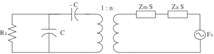
Fs
Rs C
- C 1 : n ZmS Za S
Fig. 1. Electrical equivalent circuit of a receive mode cMUT with zero electrical spurious capacitance.S is the area, Zmis the mechanical impedance of the membrane.Zais the acoustic impedance of the immersion medium.
II. METHOD
In the receive mode, the membrane is DC biased, and the displacement of membrane results in a current and voltage change. This voltage change is directly proportional to the area of the membrane. With a bias voltage adjusted at 90% of the collapse voltage, we have calculated and superimposed the voltage induced at the electrical resistance, Rs, due to each
cMUT cell in the array and calculated the transducer gain as the ratio of the power delivered to electrical load and the power available from the acoustic source.
Due to the fabrication technique of cMUTs, all cells within an array should have the same membrane thickness (tm) and the same gap height (tg). In a m-cMUT, the cells may have
varying radii (a). It is known that the collapse voltage of the cMUT is inversely proportional to the square of the radius [3]. Hence, the collapse voltages of different sized cells will not be the same. On the other hand, it is desirable to operate the cMUTs very close to the collapse voltage to maximize performance [6]. Since all cMUT cells within an array are electrically parallel, we should find a method to equalize the collapse voltages of different sized cells: If the electrodes on different sized cMUT cells are properly dimensioned, it is possible to equalize the collapse voltages. The collapse voltage of each cMUT cell is found analytically [10], [11].
We chose to work with two and three different sized cells to form the m-cMUT array. The number of cells of each kind is optimized to get a flat frequency response over the bandwidth. For the simulation of each cell, we have used the Mason equivalent of a cMUT as drawn in Fig. 1. The spring softening effect is included in the model [8] via−C in Fig. 1. Za is the acoustic impedance of water. Imaginary part of the immersion medium impedance is ignored. We have connected different
2005 IEEE Ultrasonics Symposium 0-7803-9383-X/05/$20.00 (c) 2005 IEEE 1956
sized cMUT cells in parallel as seen in Fig. 2, to an electrical resistance, Rs, the value of which is optimized to reach the
largest gain bandwidth product. We calculate the values of each parameter of cMUT: Zm, C, S, n, seen in Fig. 1 via analytical formulas.
Zm is the mechanical impedance of the membrane as
defined in [1], and corrected in [8]. The parallel capacitance is calculated via differential parallel plate approximation as in
[1].S is the area of the circular membrane.
The transformer ratio, n, is modelled to reflect partial electrode case. Finite element (FEM) simulations inspired a better model than open and short circuit methods to calculate the transformer ratio of partial electrode cMUTs .
A. Open Circuit Method for Calculation of n
In this method, it is assumed that the acoustic impedance of the immersion medium is so large that the average membrane velocity is zero [2]. As a result, when a varying force (FAC)
is superimposed on the membrane, the effective gap does not change. The calculation of the force is made from this static analysis. As found in [2],
n = CE (1)
is reached.
It is imperative to restrict the application of this method to full electrode transformer ratio calculation, since for partial electrode this calculation leads to an error as seen in Fig. 3.
Rs C - C 1 : n Zm S Za S Fs C - C 1 : n ZmS Za S Fs C - C 1 : n Zm S Za S Fs 1 1 1 1 1 1 1 2 2 2 2 2 2 2 N N N N N N N
Fig. 2. Electrical equivalent circuit of m-cMUT array in receive mode
B. Short Circuit Method for Calculation of n
In this method, it is assumed that the acoustic impedance of medium is so small that it can be neglected. As a result, an average membrane velocity, v(ω), is defined as in [3]. We find the average force by multiplying v(ω) and Zm(w). Hence
n = KFeffectiveV
AC , (2)
whereK is the lumped correction factor we introduced from the FEM comparison.
It is possible to divide the radius into infinitesimally small regions and to calculate C and E in Eq. 1. Then we can multiply and add to calculate transformer ratio for static case. However, in Eq. 2, we need to calculate the membrane impedance of the infinitely small pieces to sum to findn. To avoid unnecessary algebra, we propose a multiplierK as in Eq. 2. We found that, this factor,K, is nearly constant around 0.58
± 0.05. K is found from comparison of the analytical results
with FEM results. Fig. 3 displays the open circuit method, corrected short circuit method, and FEM (ANSYS) results of transformer ratio in partial electrode case for a = 50µm,
tm= 3µm, and tg= 0.25µm. 10 15 20 25 30 35 40 45 50 0 20 40 60 80 100 120
Electrode Radius (um)
n values (uNt/V)
Electrode Radius vs. transformer ratio a = 50 − tm= 3 − tg= 0.25 um K = 0.58
Corrected Short Circuit Method ANSYS
Open Circuit Method
Fig. 3. Comparison of turns ratio (n) calculation methods at 5.5 MHz,
a = 50µm, tm= 3µm and tg= 0.25µm
III. RESULTS
A. 2 m-cMUT Array at fc=5.4 MHz
We have used 2 different sized cMUTs to create an m-array at the center frequency 5.4 MHz. For comparison purposes we selected a uniform cMUT with the same center frequency. It was optimized for electrode size as well as the source resistance to achieve the highest gain bandwidth product. Figs. 4 and 5 display the results along with Table I. The electrode coverage is displayed in Tables I and II in terms of percentages with respect to radius. Only the regions between the specified percentages are covered with the top electrode. The phase is linear within 3-dB bandwidth.
B. 3 m-cMUT Array at fc = 8.8 MHz
1) Maximizing Gain Bandwidth Product in m-array: In
Figs. 6 and 7,Rs and number of m-array contents optimized in terms of gain bandwidth product. The phase is adjusted to be linear within 3-dB bandwidth to ensure practical use.
The number of m-cMUTs that can be used in an array is limited as the phase linearity of a cMUT fails at the second
2005 IEEE Ultrasonics Symposium 1957
0 2 4 6 8 10 12 0 0.05 0.1 0.15 0.2 0.25 0.3 0.35 0.4 f (MHz) Gain
Gain vs. Frequency Plot of the m−array and its components
m − array : composed of 57 CMUT
1 and 40 CMUT2 cMUT1 : a=85 um (%45 − % 63 Electrode) cMUT2 : a=60 um (Full Electrode)
139% frac
BW
91% fracBW
155% fracBW
Fig. 4. Gain plot of 2 element m-array and its components,tm=6 um,tg=0.6 um 0 2 4 6 8 10 12 0 0.05 0.1 0.15 0.2 0.25 0.3 0.35 0.4 0.45 f (MHz) Gain
Gain vs. Frequency Plots for 3 Different cMUT arrays, fcenter = 5.4MHz
m−cMUT array composed of 57 cMUT1 and 40 cMUT2 cMUT array composed of cMUT
3 only cMUT array composed of cMUT
4 only
cMUT1 a = 85um (%45 to %63 Electrode) cMUT
2 a = 60um (Full Electrode) cMUT
3 a = 73.4um (Full Electrode) cMUT4 a = 73.4um (%50 to %70 Electrode) 155% frac BW 100% frac BW
Fig. 5. Comparison of 2 element m-array and conventional cMUT array at center frequency 5.4 MHz,tm=6 um,tg=0.6 um
resonance frequency. Besides, in an m-array, the collapse voltage of each cMUT should be the same to operate at the highest sensitivity. This approach prevents the use of cMUTs whose individual collapse voltages are too much far apart from each other to be equalized by electrode patterning.
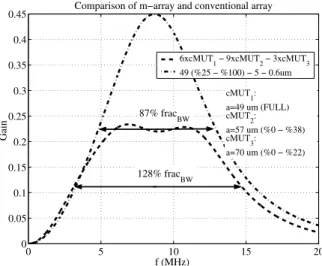
2) Maximizing Bandwidth in m-array at 8.8 MHz: In Fig. 8,
we observe that the optimization of the bandwidth and the optimization of the gain bandwidth product of an m-array are two different things with two different solutions. In Table II, it is seen that we can not only enhance bandwidth in m-arrays, but also enhance the gain bandwidth product. In this particular example, seen in Fig. 8 and Table II, the fractional bandwidth is enhanced by 58% and the gain bandwidth product by 9%. The solution to these two cases, optimization of fractional bandwidth and of fractional gain bandwidth product are differ-ent, and should be treated separately. If fractional bandwidth maximization is the criteria, the resonance frequencies of mixed cMUT cells should be separate enough to maximize bandwidth and should be close enough to avoid decrease in gain by more than 3-dB.
0 2 4 6 8 10 12 14 16 18 20 0 0.1 0.2 0.3 0.4 0.5 0.6 0.7 f (MHz) Gain
Comparison of m−array and its components
6xcMUT1 − 9xcMUT2 − 3xcMUT3 cMUT1 cMUT2 cMUT3 cMUT1: a=49 um (FULL) cMUT2: a=57 um (%0 − %38) cMUT3: a=70 um (%0 − %22) 120% frac BW 98% fracBW 67% frac BW 128% frac BW
Fig. 6. Comparison of gain bandwidth characteristics of 3 element m-array (fc= 8.8 MHz)and its components,tm= 6µm, tg= 0.6µm
0 5 10 15 20 0 0.05 0.1 0.15 0.2 0.25 0.3 0.35 0.4 0.45 f (MHz) Gain
Comparison of m−array and conventional array
6xcMUT 1 − 9xcMUT2 − 3xcMUT3 49 (%25 − %100) − 5 − 0.6um cMUT 1: a=49 um (FULL) cMUT 2: a=57 um (%0 − %38) cMUT 3: a=70 um (%0 − %22) 87% fracBW 128% fracBW
Fig. 7. Comparison of 3 element m-array and conventional cMUT array at center frequency 8.8 MHz,tm= 6µm, tg= 0.6µm 0 5 10 15 20 0 0.05 0.1 0.15 0.2 0.25 0.3 0.35 0.4 0.45 f (MHz) Gain
Comparison of m−arrays and conventional array at fc = 8.8MHz
5xcMUT4 − 6xcMUT5 −10xcMUT6 6xcMUT1 − 9xcMUT2 − 3xcMUT3 49 (%25 − %100) − 5 −0.6 cMUT 1: a=49 um (FULL) cMUT 2: a=57 um (%0 − %38) cMUT 3: a=70 um (%0 − %22) cMUT 4 a=48 um (FULL) cMUT 5 a=54 um (%0 − %42) cMUT6 a=70 um (%0 − %21) 87% fracBW 128% fracBW 146% fracBW
Fig. 8. Comparison of 3 element m-arrays (G×BW and only BW maximized)
and conventional cMUT array at center frequency 8.8 MHz, tm = 6µm,
tg= 0.6µm
2005 IEEE Ultrasonics Symposium 1958
TABLE I
COMPARISON OF2-M CMUTARRAY AND CONVENTIONAL ARRAY ATfc=5.4 MHZ
cMUT Configuration (tg= 0.6µm) fc(MHz) Gain BW (MHz) fracBW (%) G×BW (MHz) fracG×BW (%)
Uniform: a=73.4,tm= 7µm %50 - %70 Electrode 5.45 0.421 5.46 100 3.54 65.0
57×cMUT140×cMUT2 : 2 m-cMUT array 5.46 0.166 8.45 155 3.44 63.0
cMUT1(a=85,tm= 6µm) %45 - %63 Electrode 2.98 0.374 4.15 139 2.54 85.2
cMUT2(a=60,tm= 6µm) Full Electrode 7.12 0.392 6.49 91 4.06 57.0
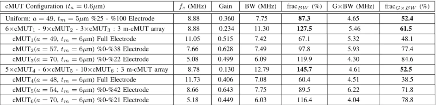
TABLE II
COMPARISON OF3M-ARRAYS AND CONVENTIONAL ARRAY ATfc=8.8 MHZ
cMUT Configuration (ta= 0.6µm) fc(MHz) Gain BW (MHz) fracBW (%) G×BW (MHz) fracG×BW (%)
Uniform:a = 49, tm= 5µm %25 - %100 Electrode 8.88 0.360 7.75 87.3 4.65 52.4
6×cMUT1- 9×cMUT2 - 3×cMUT3: 3 m-cMUT array 8.88 0.234 11.30 127.5 5.46 61.5
cMUT1(a = 49, tm= 6µm) Full Electrode 11.05 0.515 7.42 67.1 5.32 48.1
cMUT2(a = 57, tm= 6µm) %0-%38 Electrode 7.66 0.628 7.49 97.8 5.93 77.4
cMUT3(a = 70, tm= 6µm) %0-%22 Electrode 5.08 0.499 6.09 119.9 4.30 84.6
5×cMUT4- 6×cMUT5 - 10×cMUT6: 3 m-cMUT array 8.78 0.130 12.79 145.7 4.61 52.5
cMUT4(a = 48, tm= 6µm) Full Electrode 11.73 0.406 7.08 60.4 4.51 38.5
cMUT5(a = 54, tm= 6µm) %0-%42 Electrode 8.66 0.643 7.75 89.5 6.22 71.8
cMUT6(a = 70, tm= 6µm) %0-%21 Electrode 5.18 0.449 6.03 116.4 4.04 78.8
IV. CONCLUSION
We optimized the values of membrane thickness, tm, gap
width, tg, membrane radius,a, electrode radius and electrical
termination resistance, RS, to maximize the gain-bandwidth
product. We assured that the all cMUT cells have the same collapse voltage regardless of membrane radius. A linear phase within 3-dB bandwidth is also ensured. The results show that by proper dimensioning of the m-cMUTs, m-array supplies a higher fractional bandwidth than conventional cMUT arrays. We demonstrated an increase of 55% and 58% at 5.4 MHz and 8.8 MHz in fractional bandwidth.. Besides, m-arrays can have a higher gain bandwidth product than conventional cMUT arrays when the number ratios and types of different cMUT cells and source resistance are properly adjusted. We have reported an increase of 9% in fractional gain bandwidth product at 8.8 MHz.
In future work, we will fabricate the m-arrays and compare these theoretical results with experimental ones.
REFERENCES
[1] I. Ladabaum, X. C. Jin, H. T. Soh, A. Atalar, and B. T. Khuri-Yakub, ”Surface micromachined capacitive ultrasonic transducers,” IEEE Trans. Ultrason., Ferroelect., Freq. Contr., vol. 45, no. 3, pp. 678-690, 1998. [2] M. I. Haller and B. T. Khuri-Yakub, ”A surface micromachined
electro-static ultrasonic air transducer,” in Proc. IEEE Ultrason.Symp., 1994, pp. 1241-1244.
[3] A. Bozkurt, I. Ladabaum, A. Atalar, and B. T. Khuri-Yakub,”Theory and analysis of electrode size optimization for capacitive microfabricated ultrasonic transducers,” IEEE Trans.Ultrason., Ferroelect., Freq. Contr., vol. 46, pp. 1364-1374,Nov. 1999.
[4] B. Bayram, G. G. Yaralioglu, A. S. Ergun, ¨O . Oralkan, B. T. Khuri-Yakub. ”Dynamic FEM Analysis of Multiple cMUT Cells in Immersion.” Presented at the 2004 IEEE International Ultrasonics Symposium, Mon-tral, QC, Canada, Aug. 23 - 27, 2004.
[5] B. Bayram, ¨O. Oralkan, A.S. Ergun, E. Hæggstr¨om, G.G. Yaralioglu, and B.T. Khuri-Yakub, Capacitive Micromachined Ultrasonic Transducer Design for High Power Transmission, IEEE Trans. on UFFC, Vol. 52, No. 2, Feb. 2005.
[6] B. Bayram, E. Hæggstr¨om, G. G. Yaralioglu, and B. T. Khuri-Yakub,”A New Regime for Operating Capacitive Micromachined Ultrasonic Trans-ducers”, IEEE Trans. on UFFC, Vol. 50, No. 9, pp. 1184-1190, Sep 2003. [7] B. Bayram, E. Hæggstr¨om, A. S. Ergun, G. G. Yaralioglu, B. T. Khuri-Yakub. ”Dynamic Analysis of cMUTs in Different Regimes of Opera-tion.” Presented at the 2003 IEEE International Ultrasonics Symposium, Honolulu, HI, Oct. 5 - 8, 2003.
[8] S. Olcum, M. N. Senlik, and Abdullah Atalar, ”Optimization of the gain-bandwidth product of capacity micromachined ultrasonic transducers” in press.
[9] ¨O. Oralkan et al., ”Capacitive micromachined ultrasonic transducers: Next generation arrays for acoustic imaging?,” IEEE Trans. Ultrason., Ferroelect., Freq. Cont., vol. 46, no.6, pp. 1337-1340, Nov. 1999. [10] Amin Nikoozadeh, Baris Bayram, Goksen G. Yaralioglu, and Butrus
T. Khuri-Yakub, ”Analytical Calculation of Collapse Voltage of CMUT Membrane” Presented at the 2004 IEEE International Ultrasonics Sym-posium, Montral, QC, Canada, Aug. 23 - 27, 2004.
[11] S. P. Timoshenko and S. W. Woinowski-Krieger, ”Theory of Plates and Shells” McGraw-Hill, New York, 1959.
2005 IEEE Ultrasonics Symposium 1959