i
ENERGY TRANSFER, PHOTOSENSITIZATION
AND SENSING WITH NOVEL BODIPY
COMPOUNDS AND THEIR SUPRAMOLECULAR
ASSEMBLIES
A DISSERTATION SUBMITTED TO
THE GRADUATE SCHOOL OF ENGINEERING AND SCIENCE
OF BILKENT UNIVERSITY
IN PARTIAL FULFILLMENT OF THE REQUIREMENTS FOR
THE DEGREE OF
DOCTOR OF PHILOSOPHY
IN
CHEMISTRY
By
NİSA YEŞİLGÜL
June 2017
ii
ENERGY TRANSFER, PHOTOSENSITIZATION AND SENSING WITH NOVEL BODIPY COMPOUNDS AND THEIR SUPRAMOLECULAR ASSEMBLIES
By Nisa Yeşilgül June 2017
We certify that we have read this dissertation and that in our opinion it is fully adequate, in scope and in quality, as a dissertation for the degree of Doctor of Philosophy.
Engin Umut Akkaya (Principal Advisor)
Dönüş Tuncel
Özgür Altan Bozdemir
Özdemir Doğan
Canan Ünaleroğlu
Approved for the Graduate School of Engineering and Science:
Ezhan Karaşan Director of the Graduate School
iii
ABSTRACT
ENERGY TRANSFER, PHOTOSENSITIZATION AND
SENSING WITH NOVEL BODIPY COMPOUNDS AND
THEIR SUPRAMOLECULAR ASSEMBLIES
Nisa Yeşilgül
Ph.D. in Department of Chemistry Supervisor: Engin Umut Akkaya
June 2017
Fluorescent dyes have been used for decades in many applications due to their versatility, sensitivity and many other useful properties. Since their discovery in 1968, BODIPY dyes have come forward and have been used in many fields of research such as photodynamic therapy, anion/cation sensing, dye-sensitized solar cells. In this thesis, novel applications of fluorescent dyes, mainly based on BODIPY fluorophores are reported. In the first project, a photosensitizer derived from erythrosine attached to a luminol derivative is presented. The main purpose was to achieve photosensitization without requiring external excitation with light. In another project, we synthesized and characterized a series of heavy atom substituted BODIPY based photosensitizers. In a related study, the photophysical properties of a BODIPY based chemosensor substituted with benzo-21-crown-7 units were studied in the presence of various -diamino alkanes. Then, we designed a BODIPY based probe sensitive to bioreductive conditions known to be prevalent in hypoxic cancer cells. In the final chapter, we present a mechanically interlocked energy transfer cassette consisted of a distyryl-BODIPY acceptor and two donor units.
Keywords: Photodynamic therapy, photosensitizer, energy transfer cassette,
iv
ÖZET
YENİ BODIPY BİLEŞİKLERİ VE SUPRAMOLEKÜLER
TOPLULUKLARIYLA ENERJİ TRANSFERİ,
FOTODUYARLAŞTIRMA VE ALGILAMA
Nisa Yeşilgül Kimya Bölümü, Doktora Tez Danışmanı: Engin Umut Akkaya
Haziran 2017
Floresant boyalar çeşitlilik, duyarlılık ve daha pekçok kullanışlı özelliklerinden dolayı yıllardır birçok çalışmada kullanılmaktadırlar. BODIPY boyaları 1968 yılında keşfedildiklerinden beri ön plana çıkmış ve fotodinamik terapi, anyon/katyon sensörü, boya esaslı güneş pilleri olarak birçok alanda kullanılmışlardır. Bu tezde BODIPY boyaları başta olmak üzere floresant boyaların yeni kullanımları çalışılmıştır. İlk projede, luminole bağlanmış eritrosin bazlı fotoduyarlaştırıcı tasarlanmıştır. Burdaki temel amaç dışarıdan ışık uygulanmasına ihtiyaç olmadan fotoduyarlaşma sağlanmasıdır. Sonraki projede ise ağır atom içeren BODIPY temelli fotoduyarlaştırıcılar sentezlenmiş ve karakterize edilmiştir. Başka bir çalışmada -diamino alkan varlığında benzo-21-crown-7 iliştirilmiş BODIPY temelli kemosensörlerin fotofiziksel özellikleri çalışılmıştır. Daha sonra kanserli hücrelerde yaygın olduğu bilinen biyo-indirgeyici koşullara duyarlı BODIPY temelli boya dizayn edilmistir. Son bölümde ise mekanik olarak birbirine bağlanmış, distiril-BODIPY akseptörü ve iki donör biriminden oluşan enerji hasadı birimi sentezlenmiştir.
Anahtar kelimeler: Fotodinamik terapi, fotoduyarlaştırıcı, enerji transfer birimi,
v
ACKNOWLEDGEMENT
First and foremost I would like to express my sincere thanks to my supervisor Prof. Engin Umut Akkaya for his support and advice throughout my graduate studies by providing an environment conducive to independent research, creativity and hard work. I will never forget his support throughout my life.
I also would like to thank all members of the Chemistry Department for providing a multidisciplinary research atmosphere and for joyful friendships.
I owe a special thanks to Bilal Kılıç for his everlasting help, support and friendship. I am sincerely grateful to Ruslan Guliyev and Bilal Uyar for their help and guidance they provided through all these years.
Thanks to all past and present members of Akkaya Group for their help, time and friendship during all these years. Esma Uçar, Ziya Köstereli, İlke Şimşek-Turan, Seylan Ayan, Deniz Yıldız, Yahya Ismaeli, Serdal Kaya, Cansu Kaya, Simay Aydonat, Abdurrahman Türksoy, Özge Pehlivan, Merve Canyurt, Beste Gündüz and rest of the SCL (Supramolecular Chemistry Laboratory) members. It has been a great pleasure for me to work with you.
This thesis is dedicated to my mother, without whom I would never be where I am today. I would like to thank my sister and my little nephew for all love and understanding. I want to express my gratitude to my friend and my second sister Özlem Seven for her endless support and friendship. I also owe gratitude to Melih Koca for the enedless help, love and support. There is no way to thank them for their love, care, trust and encouragement they have provided all these years for me.
vi
LIST OF ABBREVIATIONS
AcOH : Acetic Acid
BODIPY : Boradiazaindacene CHCl3 : Chloroform DDQ : Dichlorodicyanoquinone DMF : Dimethylformamide DPBF : 1,3-Diphenylisobenzofuran ET : Energy Transfer Et3N : Triethylamine
FRET : Förster Resonance Energy Transfer
HEPES : 4-(2-Hydroxyethyl)piperazine-1-ethanesulfonic acid HOMO : Highest Occupied Molecular Orbital
ICT : Internal Charge Transfer IFE : Inner Filter Effect
LUMO : Lowest Unoccupied Molecular Orbital MALDI : Matrix-Assisted Laser Desorption/Ionization MS : Mass Spectroscopy
NMR : Nuclear Magnetic Resonance PET : Photoinduced Electron Transfer TFA : Trifluoroacetic Acid
THF : Tetrahydrofuran
TLC : Thin Layer Chromotography
vii
TABLE OF CONTENTS
CHAPTER 1 ... 1
1. INTRODUCTION ... 1
1.1. Photodynamic Therapy ... 1
1.1.1. History of Photodynamic Therapy ... 2
1.1.2. Mechanism of Photodynamic Therapy ... 2
1.1.3. Photodynamic Effect ... 5
1.1.4. Photosensitizers ... 7
1.1.5. Chemiluminescence ... 11
1.1.6. Chemiluminescent and Photoluminescent Systems in Photodynamic Therapy ... 13
1.2. Energy Transfer (ET) ... 15
1.2.1. Energy Transfer Mechanisms ... 15
1.2.1.1. Förster Type Energy Transfer ... 16
1.2.1.2. Dexter Type Energy Transfer... 20
1.2.2. Energy Transfer and Molecular Machines ... 22
1.3. Electron Transfer Processes ... 24
1.3.1. Internal Charge Transfer (ICT) ... 25
1.3.2. Photoinduced Electron Transfer (PET) ... 27
1.4. Fluorescent Dyes ... 28
1.4.1. Fluorescein Dyes ... 29
1.4.2. BODIPY Dyes ... 34
CHAPTER 2 ... 39
2. SINGLET OXYGEN GENERATION WITH CHEMICAL EXCITATION OF AN ERYTHROSINE-LUMINOL CONJUGATE ... 39
viii
2.2. Introduction ... 40
2.3. Results and Discussion ... 42
2.4. Conclusion ... 45
2.5. Experimental Details ... 45
2.5.1. Additional Information... 51
CHAPTER 3 ... 56
3. BODIPY-BASED PHOTOSENSITIZERS WITH LONG ALKYL TAILS AT THE MESO POSITION: EFFICIENT SINGLET OXYGEN GENERATION IN CREMOPHOR-EL MICELLES ... 56
3.1. Objective ... 57
3.2. Introduction ... 57
3.3. Results and Discussion ... 58
3.4. Conclusion ... 62
3.5. Experimental Details ... 63
3.5.1. Additional Information... 67
CHAPTER 4 ... 72
4. A STUDY ON SPECTRAL CHANGES IN TETRA-BENZOCROWN MODIFIED BODIPY INDUCED BY -DIAMINO ALKANES. ... 72
4.1. Objective ... 73
4.2. Introduction ... 73
4.3. Results and Discussion ... 75
ix
4.5. Experimental Details ... 80
CHAPTER 5 ... 86
5. TOWARDS A REACTION-BASED PROBE FOR REDUCTIVE INTRA-CELLULAR CONDITIONS ... 86
5.1. Objective ... 86
5.2. Introduction ... 86
5.3. Results and Discussion ... 87
5.4. Conclusion ... 91
5.5. Experimental Details ... 92
CHAPTER 6 ... 94
6. SUPRAMOLECULAR CONTROL OF THROUGH SPACE ENERGY TRANSFER ... 94
6.1. Objective ... 95
6.2. Introduction ... 95
6.3. Results and Discussion ... 97
6.4. Conclusion ... 106
6.5. Experimental Details ... 106
EPILOGUE ... 115
BIBLIOGRAPHY ... 117
x
LIST OF FIGURES
Figure 1: Chemical structure of the first approved photodynamic therapy agent [22]. 2
Figure 2: The modified Jablonski energy diagram. ... 3
Figure 3: Type 1 and Type 2 reactions... 4
Figure 4: Mechanism of photodynamic therapy on a tumor. Reprinted with permission from reference [23]. Copyright 2015, Bioscience Reports. ... 5
Figure 5: Therapeutic window of the body, absorbance of melanin, oxy-Hemoglobin (HbO2) and water. Reprinted with permission from reference [34]. Copyright 2012, American Chemical Society. ... 7
Figure 6: Selected examples of the recent photosensitizers from literature... 8
Figure 7: Halogenation of BODIPY core at different positions. ... 10
Figure 8: Literature examples of BODIPY based photosensitizers. ... 11
Figure 9: Peroxide containing chemiluminescent substrates. ... 12
Figure 10: Peroxide-containing bioluminescent and chemiluminescent substrates. .. 13
Figure 11: Chemiluminescence reaction mechanism of luminol. ... 14
Figure 12: Excitation of a photosensitizer, hematoporphyrin, by luminol. ... 14
Figure 13: Schematic representation of Dexter and Förster type energy transfers. ... 15
Figure 14: The coulombic and exchange energy transfer mechanisms. ... 16
Figure 15: Energy level scheme for donor and acceptor molecules. ... 17
Figure 16: A BODIPY-based Förster type energy transfer system... 20
xi
Figure 18: [2]rotaxane system for Förster resonance energy transfer. Reprinted with
permission from [98]. Copyright 2013, Royal Society of Chemistry. ... 23
Figure 19: A mechanically interlocked rotaxane in Förster resonance energy transfer. Reprinted with permission from [99]. Copyright 2005, Royal Society of Chemistry. ... 24
Figure 20: Schematic representations of fluorescent chemosensors. ... 25
Figure 21: Red and blue shifts according to energy gap between HOMO and LUMO in ICT based chemosensors. ... 26
Figure 22: Examples for ICT based sensor which has crown ether as receptor. ... 26
Figure 23.Schematic representation and mechanism of PET. ... 27
Figure 24.Example compounds for PET based chemosensors. ... 28
Figure 25: A PET sensor involving excimer formation. ... 28
Figure 26: Common fluorescent dyes in visible region [109]... 29
Figure 27: Basic numbering system of xanthenes dyes. ... 30
Figure 28: Named derivatives of fluorescein. ... 30
Figure 29: A literature examples of fluorescein based FRET system. Reprinted with permission from [115]. Copyright 2014 American Chemical Society. ... 34
Figure 30: Molecular structures of BODIPY and its precursors. ... 35
Figure 31: Sulfonated Bodipy derivatives in literature (Figure 31a). Available positions in electrophilic substation (Figure 31b). ... 35
Figure 32: Two Bodipy derivatives from the literature. Quantum yields of compound 28 and 29; 0.19 and 0.65 in MeOH, respectively. ... 36
xii
Figure 33: The substation on 3- and 5- positions on BODIPY core. ... 36
Figure 34: Tetramethyl- and pentamethyl Bodipy derivatives with 1H NMR chemical shifts in CDCl3. ... 37
Figure 35: The synthesized tetra-styryl BODIPY derivatives [131]. ... 37
Figure 36: A schematic representation of tetra-styryl BODIPY derivatives. ... 38
Figure 37: General principle for singlet oxygen generation via chemical excitation. Hydrogen peroxide would be a preferred initiator. CL: chemiluminogen module, PS: photosensitizer module, PS*: excited photosensitizer. ... 41
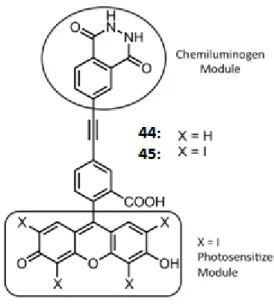
Figure 38: The structure of the immediate precursor 44 and the erythrosine-luminol conjugate 45, which was synthesized and characterized in this study, as a model for intramolecular chemical excitation to generate singlet oxygen. ... 42
Figure 39: Reaction of the singlet oxygen generated by photosensitization with 47 µM DPBF in DMSO in the presence of erythrosine-luminol conjugate 45. For the first 8 minutes the solution was kept in dark, then irradiated with 520 nm LED array for 16 minutes. Total volume was adjusted to 3.0 mL. Absorbance spectra were recorded in 2-minute intervals. ... 43
Figure 40: Change in the absorbance of 47.0 µM DPBF in DMSO in the presence of 104.0 µM of compound 44 or 45. The sample solutions contain 300 µl of pH=10.0 buffer solution (Na2CO3 and NaHCO3). After 8 minutes, chemical excitation is
induced by 300 µl of 1.5x10⁻³
M CuSO4 and 2x10⁻³ M H2O2. Total volume was
adjusted to 3.0 mL. Absorbance data were recorded in 2-minute intervals. ... 44
Figure 41: Bleaching of 47 µM DPBF in DMSO in the presence of 104 µM of compound 45. (Figure 41a) The sample solutions contain 300 µl of pH=10 buffer solution (Na2CO3 and NaHCO3). After 6 minutes, chemiluminescence is induced by
xiii
minutes intervals. During bleaching of DPBF, no change is observed in absorption spectrum of compound 45. (Figure 41b) ... 51
Figure 42: Absorbance of DPBF in DMSO at 417 nm without compound 45 or 44 (square), in the presence of compound 2 (circle), in the presence of compound 45 (triangle). ... 52
Figure 43: Bleaching of 47 µM DPBF in DMSO in the presence of 104 µM of compound 44. The sample solutions contain 300 µl of pH=10 buffer solution (Na2CO3 and NaHCO3). After 12 minutes, chemiluminescence is induced by 300 µl
of 1.5x10⁻³M CuSO4 and 2x10⁻³ M H2O2. Absorbance was measured in 4 minutes
intervals. ... 52
Figure 44: Absorbance of 47 µM DPBF in DMSO. The sample solutions contain 300 µl of pH=10 buffer solution (Na2CO3 and NaHCO3) and 300 µl of 1.5x10⁻³M
CuSO4 and 2x10⁻³ M H2O2. Absorbance was measured in 4 minutes intervals. ... 53
Figure 45: Bleaching of 47 µM DPBF in DMSO in the presence of compound 45 (Figure 45a) For the first 8 minutes sample was kept at dark, then irradiated with 530 nm light for 16 minutes. Absorbance was measured in 2 minutes intervals. During bleaching of DPBF, no change is observed in absorption spectrum of compound 45 (Figure 45 b). ... 54
Figure 46: Chemiluminescence intensity of compound 44. Intensity was measured in 1 minute intervals. ... 55
Figure 47: Chemiluminescence intensity decay curve of compound 44. Intensity was measured in 1 minute intervals. ... 55
Figure 48: Normalized absorption spectra of photosensitizers 58, 59 and 62 in DCM. ... 60
xiv
Figure 49: Singlet oxygen mediated bleaching of the trap molecule2,2'-(Anthracene-9,10-diyl)bis(methylene)dimalonic acid in the presence of Bodipy 59 (4.0μM) in water. The light source was an LED array with peak emission at 520nm. ... 61
Figure 50: Singlet oxygen mediated bleaching of the trap molecule2,2'-(Anthracene-9,10-diyl)bis(methylene)dimalonic acid in the presence of photosensitizers 58, 59 and 62 (4.0μM) in water. Absorbance at 382 nm was plotted as a function of time. The light source was an LED array with peak emission at 520nm. ... 62
Figure 51: The normalized fluorescence emission of Compound 58, 59 and 62 in CH2Cl2. ... 67
Figure 52: Singlet oxygen mediated bleaching of the trap molecule2,2'-(Anthracene-9,10-diyl)bis(methylene)dimalonic acid in the presence of Bodipy 58 (4.0 μM) in water. The light source was an LED array with peak emission at 520nm. ... 68
Figure 53: Singlet oxygen mediated bleaching of the trap molecule2,2'-(Anthracene-9,10-diyl)bis(methylene)dimalonic acid in the presence of Bodipy 62 (4.0μM) in water. The light source was an LED array with peak emission at 520nm. ... 68
Figure 54: Absorbance spectrum of trap molecule 2,2'-(anthracene-9,10-diylbis(methylene)dimalonic acid in water without photosensitizer. ... 69
Figure 55: Synthesis of tetra-crown BODIPY 63. ... 75
Figure 56: UV-visible spectra of chromophore 63 (33 M in acetonitrile) treated with diaminoethane (DAE), diaminobutane (DAB), diaminohexane (DAH), diaminodecane (DAD) and hexylamine (HA) with trifluoroacetic acid (TFA). The chromophore 63 was also treated with only diaminohexane and only trifluoroacetic acid. The final concentrations are 66 M for guest molecules and 132 M for trifluoroacetic acid. ... 77
xv
Figure 58: Emission spectra of chromophore 63 (33 M in acetonitrile) treated with diaminoethane (DAE), diaminobutane (DAB), diaminohexane (DAH), diaminodecane (DAD) and hexylamine (HA) with trifluoroacetic acid (TFA). The chromophore 63 was also treated with only diaminohexane and only trifluoroacetic acid. The final concentrations are 66 M for guest molecules and 132 M for trifluoroacetic acid and each mixture was excited at 690 nm. ... 79
Figure 59: Chemical structure of a hypoxia sensing BODIPY dye. ... 87
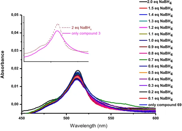
Figure 60: Fluorescence emission spectra of the meso-formyl BODIPY, compound 69 (35 µM) in pH 7.4 HEPES buffer (15 mM) and ethanol before and after addition of increased equivalents of sodium borohydride from 0.1 equivalent to 2 equivalent (Figure 60a). The photo of compound 3 (left) under a UV lamp (=254 nm and 365 nm, respectively). From left to right, rapid emission enhancement was observed upon addition of sodium borohydride (=254 nm and 365 nm, respectively) (Figure 60b). ... 89
Figure 61: The absorption spectra of the meso-formyl BODIPY, compound 69 (35 µM) in pH 7.4 HEPES buffer (15 mM) and ethanol before and after addition of increased equivalents of sodium borohydride from 0.1 equivalent to 2 equivalent... 91
Figure 62: (a)Schematic representation of BODIPY-based [2]rotaxane showing that a macrocycle (purple) was mechanically interlocked through a linker (orange), terminated by two BODIPY end groups (blue). The energy cassette components were tagged by the donor D (blue) and acceptor A (red). (b) Chemical structure of the [2]rotaxane 83. ... 95
Figure 63: The absorption spectra of [2]rotaxane 83 (1x10⁻⁶ M), compound 74 (1x10
-6
M), compound 82(2x10⁻⁶ M), and mixture M (a mixture of 74 and 82 in a molar ratio of 1:2). ... 101
xvi
Figure 64: The emission spectra of [2]rotaxane 83 (1x10⁻⁶ M), compound 74 (1x10⁻⁶ M), compound 82 (2x10⁻⁶ M), and mixture M (a mixture of 74 and 82 in a molar ratio of 1:2). The excitation wavelength of the fluorescent spectra is 500 nm. ... 102
Figure 65: The absorption spectrum of compound 74 (1x10⁻⁶ M) and the emission spectrum of compound 82 (2x10⁻⁶ M) in chloroform. ... 103 Figure 66: The emission spectra of [2]rotaxane 83 (1x10⁻⁶ M) and mixture M (a mixture of 74 and 82 in a molar ratio of 1:2) in chloroform recorded at different excitation wavelengths (500 nm and 630 nm) at room temperature. ... 104
Figure 67: Percent energy transfer efficiency of 83 (solid line) as a function of wavelength of excitation. Excitation spectrum of 83 (dotted line) and absorption spectrum of 83 (dashed line), normalized at 660 nm. (Emission data were collected at 673 nm.) ... 106
xvii
LIST OF SCHEMES
Scheme 1: Synthesis of Fluorescein. ... 31
Scheme 2: pKa dependence of fluorescein [114]. ... 32
Scheme 3: The functionalization of 2,6-diformyl-BODIPY core, 38. ... 38
Scheme 4: Synthesis of compound 45 from commercially available and/or easily accessible compounds. ... 46
Scheme 5: Synthesis of the targeted photosensitizers 58, 59 and 62. ... 59
Scheme 6: Synthesis scheme of B21C7 moietiey, compound 65. ... 75
Scheme 7: Synthesis scheme of compound 63. ... 76
Scheme 8: Synthesis of the meso-formyl BODIPY, compound 69. ... 88
Scheme 9: Synthesis scheme of acceptor and linker parts of [2]rotaxane. ... 98
Scheme 10: Synthesis scheme of the donor part of [2]rotaxane. ... 99
xviii
LIST OF TABLES
Table 1: Some approved photosensitizers and the diseases for which they are used for treatment [36]. ... 9
Table 2: Typical values of RF, Förster radius. ... 18
Table 3: Quantum yields of pKa dependent structures of fluorescein in 1%DMSO– Tris buffer solution [114]. ... 32
Table 4: Ф(1O2) values of photosensitizer ... 70
Table 5: Characteristics of micellar compounds 4, 5 and 8. Cremophor EL was used for embedding the dye. ... 71
Table 6: Fluorescence lifetime (τ) of 14 and 13 obtained from the time-resolved fluorescence measurement in CHCl3 solution. ... 105
1
CHAPTER 1
1. Introduction
1.1. Photodynamic Therapy
Photodynamic therapy, also called as photoirradiation therapy, phototherapy, photochemotherapy or PDT, is one of the promising methods for certain cancer types such as bladder cancer, head and neck cancer, gastrointestinal cancer, skin cancer, gynecological, cervical cancer or some cardiovascular diseases in consequence of its noninvasive approach [1], [2]. In this therapy, photosensitizing agents, also called as photosensitizers, are brought in locally or intravenously and these agents localized in cancer tissues [2].After administration of a photosensitizer (PS), usually 1 to 3 days depending on type of the drug, it is activated by light of certain wavelength, preferentially by red or near infrared light.
An acceptable photosensitizer should be inactive or in other words „harmless‟ without light. However, by applying a suitable light, photosensitizer gets activated and reactive oxygen species as singlet oxygen (1O2) are generated. Depending on the
localization of photosensitizer, surrounding molecules such as DNA, proteins, lipids or tumor tissues can be damaged oxidatively [3], [4]. Therefore, selectivity of photosensitizer is an important issue such that when a phtotosensitizer is designed for the target tumor cells, it will be localized selectively, so when the light at therapeutic window is applied surrounding healthy tissues will not be photodamaged.
In a successful photodynamic therapy application, therefore, photosensitizer should have certain properties. Photosensitizer, photodynamic therapy agent, should absorb light at near-IR region, also known as therapeutic region. This is because light below this range cannot penetrate deeply cancer tissue and above this range, water in the body absorbs light [5]. Absorption maximum of a PDT agent is also important because it determines singlet oxygen generation efficiency as it will be mentioned later. Singlet oxygen is one of the key elements for a successful PDT application.
2
1.1.1. History of Photodynamic Therapy
Light was a widely used treatment in many diseases such as psoriasis, rickets or skin cancer by ancient nations as Egyptians, Chineses or Indians for thousands of years [6], [7]. However, photodynamic therapy is known for more than a hundred year [8]. In 1900, cytotoxic affect of acridine orange is observed with day light [8]. In 1903, Niels Finsen was awarded Nobel Prize for treatment of smallpox and cutaneous tuberculosis by phototherapy [9]. After mid 1900s, many successful studies with hematoporphyrin derivative (HPD) were reported [10]–[14]. Therefore, clinical trials of this drug were initiated in 1976 [1]. The first human trials were successful and a hematoporphyrin derivative was used for the treatment of recurrent bladder cancer. These cancer tissues were destroyed by necrosis by slowing down malignant tissue growth. Later 25 patients were treated by the same method successfully [15].
In later years, photodynamic therapy was used in different cancer types and different diseases as brain tumors, skin carcinoma, cholangioma, pancreatic carcinoma etc. [16]–[21]. In 1993, porfimer sodium was reported as the first approved photodynamic therapy agent (Figure 1) [22].
Figure 1: Chemical structure of the first approved photodynamic therapy agent [22].
1.1.2. Mechanism of Photodynamic Therapy
Generation of reactive oxygen species is the crucial step of photodyanmic theraphy application. When light at appropriate wavelength is applied, photosensitizer is
3
energetically activated (PS 1PS*) The formed excited singlet state is not stable and has a very short life time, which is in nanoseconds. Therefore, here, these short lifetime species may decay to its ground state so that fluorescence occurs or these species can go for a more stable triplet state by intersystem crossing (Figure 2).
Figure 2: The modified Jablonski energy diagram.
The triplet state species has a lifetime in microseconds, longer than singlet state. In this state, generation of singlet oxygen is possible or electron falls back to its ground state so that delayed fluorescence, phosphorescence occurs. The former pathway is favored by attaching heavy halogens to photosensitizers (heavy atom effect). In this step, reactive oxygen species can form by two different mechanisms. In the type I reaction, triplet state phtosensitizer transfers its energy to surroundings as protons or electrons so that radicals or radical ions form. These radicals or radical ions react with oxygen, therefore, singlet oxygen species form. In type II reactions, triplet state phtosensitizer transfers its energy directly to surrounding oxygen molecules to yield reactive oxygen species (Figure 3).
4
Figure 3: Type 1 and Type 2 reactions.
Reactive oxygen species have very short lifetimes and are highly reactive, therefore, only tissues where photosensitizers are localized, are treated with PDT. It should be noted that PDT efficiency decreases as the oxygen concentration in targeted tissue decreases [1].
The photodamage of photosensitizer results as apoptosis or necrosis in PDT applied tissues (Figure 4) [23]. Apoptosis is a programmed cell death and characterized by cell shrinkage [24]. Necrosis is an unnatural cell death and characterized by swelling of the cell. The cell deaths are the cytotoxic outcome in photodynamic application [25].Other then cytotoxic drawback, PDT has some other minor results in human body as prolonged skin sensitization to the sunlight so that patients should avoid at least 1 to 4 weeks away from sunlight [26]. The efficiency of treatment can be affected by light wavelength, light doses, photosensitizer administration to body [27].
5
Figure 4: Mechanism of photodynamic therapy on a tumor. Reprinted with permission from
reference [23]. Copyright 2015, Bioscience Reports.
1.1.3. Photodynamic Effect
In photodynamic therapy application, photosensitizers also can be mentioned as drugs in clinical applications, light and oxygen (or cytotoxic oxygen) are the basic elements. In order to generate a successful treatment, all these components of PDT should provide optimum standards. As reactive oxygen species form, they directly react with surrounding cellular components such as proteins, lipids, nucleic acids [28]. Therefore, formation of reactive singlet oxygen species triggers immediately cellular damage and vascular shutdown so that immune response system is activated by cellular destruction.
As it is mentioned, necrosis and apoptosis occur as cellular death by PDT. The type of cellular death is determined by the localization of drug and quantity of reactive singlet oxygen. In apoptosis, photosensitizers are generally located in mitochondria or endoplasmic reticulum. In necrosis, however, photosensitizers are generally located in lysosomes or in plasma membrane [29].The targeted phtotosensitizers are preferable choices for succesfull PDT applications with minor side affects.
Besides targeting property of a photosensitizer, effective singlet oxygen generation capability is also a crucial step in photodynamic therapy applications. Spin orbit
6
coupling can be increased by spin forbidden transition from ground state oxgen (3O2)
to excited state oxygen [30], [31].
In the above formula, L is angular momentum number and S is spin operator and spin-orbit Hamiltonian term is shown with HSO. Z is atomic number, ao is Bohr‟s
radius, m is mass of electron, c is speed of light, n is principle quantum number and e is electron charge.
As it can be found from spin orbit Hamiltonian formulation, HSO is proportional to
fourth power of atomic number. Therefore, when heavy atoms are fused in photosensitizer core, spin-orbit coupling increases so as spin-forbidden transition of singlet-triplet states.
In living organisms, there are many absorbing molecules, therefore, light penetration differs according to where it is applied. For instance, melanin collagens, hemoglabins absorb different regions of visible light or some aromatic compounds as aminoacids phenylalanin absorbs near visible light (Figure 5) [32]. Therefore, longwavelength light is the essential key for sufficient tissue penetration. However, it should be considered that above 900 nm, water absorbs the applied light. That‟s because the therapatic window, which is between nearly 650-900 nm, gives the best penetration depth in photodynamic theraphy applications. Thus, the use of photosensitizers in PDT application is done accordingly [33].
7
Figure 5: Therapeutic window of the body, absorbance of melanin, oxy-Hemoglobin (HbO2) and
water. Reprinted with permission from reference [34]. Copyright 2012, American Chemical Society.
Therefore, absorption maxima of a photosensitizer must be in the therapeutic window in order to generate effective reactive singlet oxygen species so that it can absorb the given light strongly.
1.1.4. Photosensitizers
As the key element of photodyanmic therapy application, there are extensive studies for generation of effective photosensitizers [35]. The first generation photosensitizers generally based on porphyrin [36]. For example, photofrin is a porphyrin based photosensitizer and does not have a good absorption at therapeutic window, has an absorption maxima at 630 nm. Therefore, light does not penetrate deeply and also painful edema is the side effect of this drug application [37].
Due to the drawbacks of photofrin, hematoporphyrin type of drugs and other drug types as synthetic chlorins, which have absorption maxima at therapeutic window, are more favorable (Figure 6) [36]. 5-Aminolaevulinic acid (5-ALA), which is a porphyrin precursor, is another clinically approved photosensitizer. It is used in skin cancer [38]. Sessler et al. reported new type of photosensitizers in 1988 [39]. Texaphyrins have common properties with porphyrin derivatives as high intensity colors. These dyes have an absorption maxima at near IR region.
8
Figure 6: Selected examples of the recent photosensitizers from literature.
After the first clinical trials in 1976, photodynamic therapy is used in the treatment of many diseases [1]. Many approved phtosensitizers are used in clinical applications widely in cancer treatments (Table 1). Lung, bladder, neck and head, prostate, nonmelanoma cancer types are just a few of the examples [40]–[47]. Besides trials of some cardiovascular diseases are conducted and approval of new treatments are soon to be expected in the near future [48].
9
Table 1: Some approved photosensitizers and the diseases for which they are used
for treatment [36].
Photosensitizer Trade Name Approval Wavelength (nm)
Area of Use
Taloporfin Sodium LS11 Phase I&II
664 Choroidal
neovascularization, liver and colorectal metastasis
Motexafin Lutetium MLu, Lutex, Lutrin
Phase I 732 Prostate,
Atherosclerosis
Silicon pthalocyanine-4 PC-4 Phase I 672 Skin
mTHPC Foscan 2001 EU 652 Head and neck, prostate, pancreas, esophagus,
mesothelioma
Methyl aminolevulate-PpIX
Hexvix 2005 EU 405 Detection of Bladder tumors
Pd-bacteriopheophorbide
Tookad Phase I 762 Prostate
Porfimer Sodium Photofrin 1998 FDA
630 Lung, Barrett‟s esophagus
10
Boron dipyrromethene, BODIPY, dyes are attractive phtosenstizer agents with their high extinction coefficient and phtostabilities [49]. In 2005, a BODIPY derivative is synthesized as a photosensitizer. In this work, Nagano et al., show that haloganated BODIPY generates singlet oxygen species with intersystem crossing, 2 (Figure 7). In another work, heavy atoms are introduced to 3-, 5- and 2-, 6- positions of BODIPY core, 3, 4 and 5 (Figure 7). As singlet oxygen generation efficiencies of BODIPY derivatives are compared, it is observed that BODIPY derivatives that are haloganated in 2-, 6- positons have high fluorescence and high singlet oxygen quantum yield. Also, It should be noted that these BODIPY derivatives are highly stable in light [50].
Figure 7: Halogenation of BODIPY core at different positions.
O‟Shea et al. also reported a new class of BODIPY based photosensitizers [51]. These aza-BODIPY derivatives have a strong absorption at near-IR region, 6 and 7 (Figure 8). In figure 8, there are some examples of photosensitizers that can work in the therapeutic window of the body [52]–[54]. Akkaya et al. has published a nice example of a smart photosensitizer that takes into account cancer parameters, 9 [54]. In this article, the increased acidity amounts in cancer cells were used as one parameter for photosensitizer to work. The other parameter was the sodium concentration of the medium. In acidic medium, pyridine groups were protonated and bathochromic shift in absorbance was observed. Light at 660 nm was applied, only
11
protonated molecules show photodynamic work and by Na+ binding photoinduced electron transfer, PET, was blocked. Therefore, a smart photosensitizer that works only in cancer cells that has low pH and high Na+ concentration.
Figure 8: Literature examples of BODIPY based photosensitizers.
1.1.5. Chemiluminescence
As it is stated before, typical photosensitizers absorb at 600-800 nm so UV light to excite these molecules has some problems related to penetration depth of light [35], [55]–[58]. Therefore, photodynamic theraphy with these common photosensitizers are suitable only for tumors under skin with a ceratin depth interval (~1cm) or on skin. Also the method is not suitable for metastatic tumors, which are main reason of cancer deaths [55], [56]. Therefore, photosensitizers, which can be activated without any external light source, are important in photodynamic applications. In self illuminating photodynamic therapy system, nonradiative energy is transferred from suitable donors to acceptor molecules. The energy transfer porcess is either
12
chemiluminescent resonance energy transfer (CRET) or bioluminescent resonance energy transfer (BRET) [55], [58]–[64]. During the process, chemiluminescent or bioluminescent donors activate photosensitizer intracellulary without using any light source.
Chemiluminescence is the emission of light, which is formed as a result of a chemical reaction. When chemiluminescence occurs in living cells by enzyme catalyzation, it is called as bioluminescence [65]–[69]. Bioluminescence is a sub-type of chemiluminescence. Bacteria, insects and worms are some of the living organisms that bioluminescence can be observed [65], [66]. Many of the chemiluminescent substrates contain an oxygen-oxygen peroxide bond. The excited state products form by thermal activation in this case [65], [66], [70]. Dioxetanedione, R1,R2,R3,R4-dioxetane and R1,R2-dioxetanone (Figure 9) are the
main groups for substrates that contain peroxide [65], [66], [70], [71]. The main criterion for peroxide containing substrates is whether they can provide enough energy for chemiexcitation of acceptor during the thermal process.
Figure 9: Peroxide containing chemiluminescent substrates.
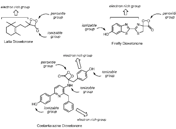
Peroxide-containing bioluminescent and chemiluminescent substrates have three parts. A peoxide bond is one of these parts [65], [66], [70]. The peroxide bond breaking results with thermally activated ground state to excited state chemiexcitation. The other part is electron rich moity. This part arranges the electron or charge transfer for peroxide ring decomposition. The final part is ionazable groups that are responsible of arranging activation energy for thermal decomposition (Figure 10) [72]–[74].
13
Figure 10: Peroxide-containing bioluminescent and chemiluminescent substrates.
1.1.6. Chemiluminescent and Photoluminescent Systems in Photodynamic Therapy
The oxidation of luminol is one of the many reactions that reasulted with emission of light [75], [76]. A basic solution and an oxidant catalyst as Fe2+, Cu2+, Co2+, periodate ions or hydrogen peroxide is reaquired for the oxidation of luminol. As it is shown in figure 11, the interaction of luminol with hydroxide anions results with dianion formation. The resulted dianion reacts with oxygen and the oxidation product forms. Aminophthalte ion in excited state has an emission at max 425 nm and a blue chemiluminescence (Figure 11) [75], [77]. There are several examples of use of luminol derivatives in photodynamic therapy studies. For instance, Wang and coworkers study chemiluminescence of luminol in photodynamic theraphy [61]. In the study, oligo (p-phenylene vinylene) (OPV) as the photosensitizer absorbs chemiluminescence of luminol. Luminol, hydrogen peroxide and horseradish (HRP) were used to induce chemiluminescence. OPV has an absorption range of 350-550 nm and luminol has an emission maxima at 425 nm. Therefore, in this case spectral
14
overlap is also achieved chemiluminescence resonance energyu tarnsfer CRET or bioluminescence resonance energy tarnsfer BRET. CRET is also favorable by considering the fact that dianionic excited product of luminol chemilumescence and cationic OPV.
Figure 11: Chemiluminescence reaction mechanism of luminol.
Firer and coworkers injected luminol, hydrogen peroxide and as a catalyst Fe2+ to murine hybridoma cells in order to activate hematoprophyrin, which was used as photosensitizer (Figure 12) [55]. The results showed that luminol induces intracellular chemiluminescence and photodyanmic theraphy activation is induced cytotoxicity in %95 of cells.
15
1.2. Energy Transfer (ET)
The design and synthesis of artificial energy light harvesting systems have been an attractive area in supramolecular studies since there are many inspiring examples of light-harvesting antenna systems [78]. There are two different types of energy transfer mechanism: Dexter and Förster energy transfers (Figure 13).
Figure 13: Schematic representation of Dexter and Förster type energy transfers.
1.2.1. Energy Transfer Mechanisms
Resonance energy transfer is a photophysical process that occurs between an electronically excited donor molecule and an acceptor molecule so that at the end, lifetime of donor molecule decreases. In supramolecular systems, energy transfer can be observed between two localized electronically excited states by radiationlessly. Non-radiative energy transfer can be explained by two different mechanisms, which are inductive resonance and exchange interaction. The inductive resonance mechanism also called as Förster type mechanism (Coulombic energy transfer) is a long range mechanism, on the other hand, exchange mechanism also called as Dexter type mechanism is significant only less than 10 Å distance between donor and acceptor molecules [79]. The orbital aspects of both energy transfer mechanisms are represented in figure 14.
16
Figure 14: The coulombic and exchange energy transfer mechanisms.
1.2.1.1. Förster Type Energy Transfer
In an interaction of a donor molecule and an acceptor molecule, non-radiative energy transfer of excitation energy occurs and if the emission spectrum of donor molecule and the absorption spectrum of acceptor molecule overlaps, the energy transfer between donor and acceptor could be possible (Figure 15) [80], [81]. This type of energy transfer is called as Förster (resonance, inductive resonance, Coulombic or through space) Resonance Energy Transfer.
Förster Type energy transfer does not require a physical contact or interaction between donor molecule or acceptor molecule [82], [83]. However, for an effective energy transfer process, donor chromophore should be fluorescent. If the donor molecule is a fluorescent molecule, the energy transfer is called as fluorescence energy transfer (FRET). FRET requires that the energy gap between ground and excited states should be nearly equal for both donor and acceptor molecules. Therefore, in an interaction of a donor molecule and an acceptor molecule, non-radiative energy transfer of excitation energy occurs and if the emission spectrum of donor molecule and the absorption spectrum of acceptor molecule overlap, the energy transfer between donor and acceptor could be possible (Figure 15). The dipole-dipole term is the most important term in Förster theory.
17
Figure 15: Energy level scheme for donor and acceptor molecules.
In the energy level scheme of donor and acceptor molecules, coupled transitions where vibrational relaxation is faster than energy transfer can be observed and the integral overlap between absorption of acceptor and the emission of donor is shown. The spectral overlap of donor and acceptor occurs when an electron in LUMO of donor molecule goes to its HOMO, energy is released so that an electron in HOMO of acceptor molecule goes to its LUMO.
In early 1920s, J. Perrin stated that if molecules can be separated by a sufficient distance, energy can be transferred from a donor molecule to an acceptor molecule
18
non-radiatively. Later on, Förster in 1946 showed that the energy transfer possible up to 10 nm and explained the energy transfer quantitatively where
k
F= k
rad(R
F/R)
6krad is radiative rate, RF is critical distance or Förster radius [84]. Förster radius is
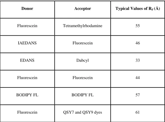
determined by the overlap of emission spectrum of donor and absorbance spectrum of acceptor molecules. RF is generally in a range of 1-8 nm. Some literature RF values
are given in table 2 [85].
Table 2: Typical values of RF, Förster radius.
Donor Acceptor Typical Values of RF (Å)
Fluorescein Tetramethylrhodamine 55
IAEDANS Fluorescein 46
EDANS Dabcyl 33
Fluorescein Fluorescein 44
BODIPY FL BODIPY FL 57
Fluorescein QSY7 and QSY9 dyes 61
Two different methods can be used to calculate Förster Type Energy Transfer efficiency, which are steady state and time resolved [86]. In steady state approach, the amount of decrease in quantum yield of donor molecule is used. However, self absorption of emitted light by the same molecule or surrounded ones is a problem
19
which is called as inner filter effect. In order to avoid inner filter effect, dilute solutions should be used. FRET efficiency is formulated as:
E = 1 -
DA/
DWhere, ΦDA is quantum yield of donor in the presence of acceptor and ΦD is quantum
yield of donor in the absence of acceptor. FRET efficiency can be calculated with a different formulation in the same approach:
E = A
A(
D) / A
D(
D) * [I
AD(
Aem) / I
A(
Aem) - 1
]
In this formulation, AA is absorbance value of acceptor at the maximum absorbance
wavelength of donor and AD is absorbance value of donor at the maximum
absorbance wavelength of donor. IAD is integrated emission area of acceptor in the
presence of donor at λAem and IA refer to integrated emission area of acceptor in the
absence of donor at λAem.
In time resolved approach, time resolved emission data of donor and acceptor molecules is used. Since the inner filter effect is eliminated here, this method provides much more accurate data. FRET efficiency can be formulated as shown below, in the case of decay emission is a single exponential:
k
FRET= 1/
DA– 1/
DE =
Dk
FRET/ (1+
Dk
FRET)
where τD refers to excited state lifetime of donor in the absence of acceptor and τDA
refers to excited state lifetime of donor in the presence of acceptor.
In figure 16, there is a BODIPY based, Förster type energy transfer system shown [87]. The system consists of an acceptor, perylene diimide core, and four donors, four BODIPYs. The increased number of donors increases the extinction coefficient. The extinction coefficient of the molecule is 250000 M-1 cm-1 at the maximum
20
absorbance wavelength of donor molecules, at 526 nm. The critical Förster radius is determined to be 4.7 nm and with energy transfer efficiency of 99%.
Figure 16: A BODIPY-based Förster type energy transfer system.
1.2.1.2. Dexter Type Energy Transfer
The interaction between highest occupied orbital of donor molecule and lowest unoccupied orbital of an acceptor molecule is called as Dexter type energy transfer or electron exchange type mechanism or through bond energy transfer [88].The orbital interaction limits the distance between acceptor and donor so that maximum distance is generally 10 Å and the rate constant of Dexter type energy decreases exponentially with the distance to nuclei [79]. The rate constant is formulated as below:
k
ET= K J exp(-2R
DA/ L)
where K is orbital interaction, J represents the overlap integral between emission of donor molecule and absorption of acceptor molecule, RDA is the donor acceptor
21
There are different molecular systems with this type of energy transfer. Two anthracene-BODIPY based systems 11 and 12 are shown in figure 17. The important point about the energy transfer system 12 is that it is much more efficient than 11 and when the molecule is excited at the maximum absorption of anthracene, energy transfer occurs very fast, which is about ~200 fs. Anthracene unit behaves as donor and BODIPY serves as acceptor in this system. It‟s because of the parallel alignment of S1 transition dipole moment of donor and S0 transition of acceptor units and due to
the steric hindrance in 11, conjugation is disturbed and energy transfer decreased [89]. The compound 13 is another example of a BODIPY based energy transfer cassette in which two donor units are attached to an acceptor unit with conjugated bridges. In this literature example, the decrease in through bond energy transfer with increased distance is observed [90].
22
1.2.2. Energy Transfer and Molecular Machines
Rotaxanes and catenanes have been studied for development of mechanically bonded systems. Switches, molecular shuttles are a few examples of mechanically bonded molecular machines [91]–[97]. There are many attempts to construct rotaxanes in energy transfer systems. In these systems, chromophoric units can be placed in axle or wheel parts. Rotaxane systems are especially favorable in Förster energy transfer cassettes due to having a chance to place donor and acceptor components in close distances.
Brouwer and coworkers have published a study of [2]rotaxane system for Förster resonance energy transfer as the first known example of pillararene based rotaxane [98]. In the design of energy transfer cassette, wheel component constructed from pillar[5]arene and a dipyrene is attached to pillar[5]arene. As an axle, pyridinium is used and perylene unit is used as the stopper (Figure 18). In the mechanically interlocked rotaxane system, efficient Förster resonance energy transfer from wheel component to stopper component is proved.
23
Figure 18: [2]rotaxane system for Förster resonance energy transfer. Reprinted with permission from
[98]. Copyright 2013, Royal Society of Chemistry.
There is another example of Förster resonance energy transfer in a mechanically interlocked system (Figure 19) [99]. In the synthesized rotaxane system, Coumarine 2 is placed on the axle and served as the donor component and Coumarine 343 placed on the macrocycle and served as the acceptor. A schematic representation of rotaxane system shows that a macrocycle (red) is mechanically interlocked by a hydrogen bonding site (green) to an axle (black). Bulky group represented as yellow.
24
Figure 19: A mechanically interlocked rotaxane in Förster resonance energy transfer. Reprinted with
permission from [99]. Copyright 2005, Royal Society of Chemistry.
1.3. Electron Transfer Processes
A fluorescent probe can be designed by the combination of a fluorophore to provide optical signal from a chemical input and a receptor to provide the sensitivity and selectivity towards the intended material [100]. In a fluorescent probe, receptor can be directly connected to fluorophore to from a conjugated system or there can be a spacer between the fluorophore and the receptor (Figure 20) [101].
25
Figure 20: Schematic representations of fluorescent chemosensors.
1.3.1. Internal Charge Transfer (ICT)
In internal charge transfer (ICT) system, a receptor is directly attached to a fluorophore, as a result a conjugated fluorescent probe forms (Figure 21). When an analyte binds through the receptor, dipole moment changes causing intramolecular charge transfer from donor to acceptor. Therefore, a spectral shift in absorption and emission is observed.
The type of the ligand determines the character of the shift in absorption and emission spectrum according to the electronic character of the receptor and the analyte. When an electron donor group is attached to a fluorophore, a cation binding as an analyte will decrease electron density and the conjugation which means that cation binding destabilize the excited state so the energy gap between HOMO and LUMO levels increases. Thus, there will be a blue shift in absorbance and emission spectrum [102].
26
Figure 21: Red and blue shifts according to energy gap between HOMO and LUMO in ICT based
chemosensors.
On the other hand, when an electron withdrawing group is attached to a fluorophore, a cation binding as an analyte will increase electron density and the conjugation which means that cation binding stabilize the excited state so the energy gap between HOMO and LUMO levels decreases. Thus, there will be a red shift in absorbance and emission spectrum [103]. In figure 22, there are examples for ICT based systems that show blue shift in case of metal ion binding [104], [105].
27
1.3.2. Photoinduced Electron Transfer (PET)
In photoinduced electron transfer (PET) systems, the conjugation is prevented by placing a spacer between a fluorophore and receptor but electronic interaction can be still possible (Figure 23) [106]. The PET working mechanism starts with the absorption of photon by a fluorophore, therefore, electron is excited from highest occupied molecular orbital (HOMO) to lowest unoccupied molecular orbital (LUMO). After excitation an electron from the donor atom move to the HOMO of fluorophore. Since the HOMO level of fluorophore is fully occupied, the excited electron of fluorophore cannot return, as a result fluorescence is quenched.
Figure 23: Schematic representation and mechanism of PET.
The figure 24 shows some literature examples for PET based chemosensors for different metal ions. In these examples, fluorescence is quenched by the binding of some alkali and transition metal ions [107].
28
Figure 24: Example compounds for PET based chemosensors.
In figure 25, The PET based system consists of two pyrene moieties attached to a diazacrown ether. In the case of a cation binding, as it is expected, monomer to excimer ration changes and fluorescence increases due to decreased PET from the nitrogen atoms of diazacrown ether to pyrene groups. The monomer to excimer ratio strongly depends on the size of the binding cation and K+ and Ba2+ shows the highest stability [108].
Figure 25: A PET sensor involving excimer formation.
1.4. Fluorescent Dyes
Fluorescent organic dyes, as it is mentioned before, have many applications. A wide variety of fluorescent dyes with emission in ultraviolet (UV), visible (VIS), infrared (IR) and near-infrared (NIR) regions can be observed in different applications. In
29
figure 26, there are fluorescent organic dyes with different emission wavelengths [109].
Figure 26: Common fluorescent dyes in visible region [109].
The UV region mainly contains coumarin, pyrene and naphthalene based dyes and the IR region contains BODIPY, fluorescein, cyanine and rhodamine dyes.
1.4.1. Fluorescein Dyes
Fluorescein dyes are also called as 2-(6-hydroxy- 3-oxo-xanthen-9-yl)benzoic acid synthesized first time in 1871 by Adolph Von Baeyer by the condensation of resorcinol and phthalic anhydride in the presence of a strong acid and a catalyst, sulfuric acid and zinc chloride, respectively [110]. Fluoerescein dye derivatives have many applications in biotechnology considering their high quantum yield and relatively good water solubility [111]. As in BODIPY dyes they have many literature
30
application examples as chemosensors, DNA attachments, laser applications and photosensitizers [112], [113]. The basic numbering of the xanthene core of Fluorescein dyes are shown in figure 27 .
Figure 27: Basic numbering system of xanthenes dyes.
The properties of fluorescein dyes can be improved with different functionalization on the core. Halogenation, alkylation, sulfonation or other specific type of reactions can be used to improve absorption or emission wavelengths or quantum yields. In literature, there are many examples of fluorescein derivatives (Figure 28).
31
The synthesis of fluorescein dyes consists of a condensation of two equivalents of resorcinol and one equivalent of phthalic anhydride in the presence of a strong acid as sulfuric acid, later it was found that using zinc chloride as the catalyst increaes the yield.
Scheme 1: Synthesis of Fluorescein.
Fluorescein has a lactone locked form in acidic conditions and going from neutral conditions to acidic conditions, the transformation from an open from to lactone form, fluorescein undergoes five different forms. The five different forms of fluorescin depending on pH can be seen in scheme 2.
32
Scheme 2: pKa dependence of fluorescein [114].
The phenol and carboxylic groups on fluorescein core are almost ionized completely when pH is higher than 9. As pH get lowers (pKa~6.4), first the phenol group in dianion protonates and monoanion forms and as the acidification of monoanion (pKa<5.0), carboxyl group gets protonate and fluorescein in neutral form is produced. A fluorescein cation forms with further acidification (pKa~2.1). At pKa= 2.4, a colorless nonfluorescent lactone form of fluorescein is produced. The monoanion and the dianion forms of fluorescein are the only ones that are fluorescent and with quantum yields of 0.36 and 0.93, respectively (Table 3) [114].
33
Table 3: Quantum yields of pKa dependent structures of fluorescein in 1%DMSO–
Tris buffer solution [114].
Species Quantum yield
dianion (ring opened phenolate) 0.93
anion (ring opened phenol) 0.36
neutral forms 0.29
cation 09-1.0
In literature, there are many fluorescein derivative examples. In figure 29, there is a FRET system based on fluorescein dye. In this system, a bispyrene moiety works as donor unit and fluorescein serves as the acceptor unit. Highy efficiency of system is provided two crucial parts. Emission of pyrenyl excimer has an overlap with the absorption of fluorescein unit. Secondly, triggiring lactone to ring open form of fluorescein by the target. Therefore, a trun-on probe is produced [115].
34
Figure 29: A literature examples of fluorescein based FRET system. Reprinted with permission from
[115]. Copyright 2014 American Chemical Society.
1.4.2. BODIPY Dyes
4,4‟-difluoro-4-bora-3a,4a-diaza-s-indacene is abbreviated as BODIPY and synthesized by Treibs and Kreuzer in 1968 first time. They have been used in many applications such as in energy transfer systems, PDT applications, in solar cell systems or in biological labeling [116], [117].
The BF2 bridge in BODIPY dyes increases the planarity of dipyrrin so that BODIPY
dyes have highly delocalized system (Figure 30). There are numerous distinctive properties of BODIPY dyes compared to other organic dyes. They have high fluorescent quantum yields and narrow emission bands in UV and also near-IR region. BODIPY dyes also have high thermal and photostabilities. Furthermore, their ease of solubility in organic solvents and ease of functionalization make them attractable in many applications as it is mentioned above. There are different examples of BODIPY derivatives with functionalization at different positions [49], [118]–[126].
35
Figure 30: Molecular structures of BODIPY and its precursors.
In order to functionalize of 2-,6- positions, an electrophilic reaction such as sulfonation, halogenation is required (Figure 31a). It is because the 2- and 6- positions hold less positive charge (Figure 31b). Heavy atom, Br or I, introduction to 2- and 6- positions cause a significant red shift of absorption and emission maxima. This type of functionalization is favored by PDT applications due to intersystem crossing resulting with low fluorescence.
Figure 31: Sulfonated Bodipy derivatives in literature (Figure 31a). Available positions in
electrophilic substation (Figure 31b).
In the case of the effect of functionalization position on absorption and emission bands, it can be stated that the substitution of aryl groups on the meso position has a minor effect (Figure 32). However, substitution on 1-, 7- positions increases the quantum yield according to unsubstituted ones [118]. It is because of free rotation of phenyl ring on meso position is prevented with 1-, 7- substitution.
36
Figure 32: Two Bodipy derivatives from the literature. Quantum yields of compound 28 and 29; 0.19
and 0.65 in MeOH, respectively.
BODIPY dyes with extended conjugation and dispersed emission maxima can be synthesized by the functionalization on 1-, 3-, 5- and 7- positions with different type of reactions such as transition metal catalyzed reactions (Suzuki, Sonagashira, Stille and Heck couplings). The substation on 3- and 5- positions give BODIPY derivatives with shifted emission and absorption maxima such as thioalkoxides or amino groups on these positions cause bathochromic shift (Figure 33). The acidic character of methyl groups on these positions gives a high yield with Knoevenagel reactions [127].
Figure 33: The substation on 3- and 5- positions on BODIPY core.
Knoevenagel condensation reaction is a nucleophilic addition of active hydrogen compound to a carbonyl compound. The reaction medium requires a basic environment and removal of water, Dean-Stark apparatus is used for this purpose. This method results with high results with substitution on 1-, 3-, 5- and 7- positions. Therefore, in one Knoevenagel reaction, mono-, di-, tri-, and tetrastyryl-Bodipy derivatives can be synthesized in an order [128]–[130].
37
In 2009, Akkaya et al synthesized the first tetra styryl derivative of BODIPY dye [131]. In this study, it‟s suggested that 1,7- positions of BODIPY core is as acidic as methyls at 3-, 5- positions. The acidic character of different positions can be observed by Mulliken-charge analysis on the core carbon atoms of tetramethyl-BODIPY (Figure 34).
Figure 34: Tetramethyl- and pentamethyl Bodipy derivatives with 1H NMR chemical shifts in CDCl3. In this study, bromine atoms in 2-, 6- positions and pyridine groups in tetrastyryl substitution were used (Figure 35).
Figure 35: The synthesized tetra-styryl BODIPY derivatives [131].
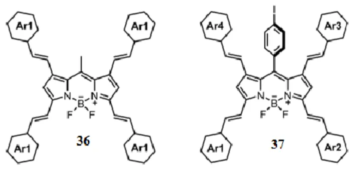
After the mentioned article of tetrastyryl substitution, Ziessel et.al. synthesized different BODIPY derivatives bearing same and different aldehydes (Figure 36) [132]. The new tetrastyryl substituted BODIPY derivatives have absorption maxima at 720 nm and emission maxima at 800 nm. Ziessel et.al. also reported that methyls at 3-, 5- positions on BODIPY core are more reactive according to methyls at 1-, 7- positions in Knoevenagel condensation.
38
Figure 36: A schematic representation of tetra-styryl BODIPY derivatives.
In another study, Liu et.al. substituted 2, and 6, positions with formyl groups and they observed that 1, and 7- positions more attractive to go Knoevenagel reaction according to the 3, and 5, positions (Scheme 3) [133]. By this approach, different BODIPY derivatives, functionalized first by 1- and/or 7- positions and then allowing to functionalize on methyl groups at 3- and 5- positions.
Scheme 3: The functionalization of 2,6-diformyl-BODIPY core, 38.
In the study, different groups were used to functionalize the BODIPY core, 38. As it is shown in scheme 3, oligo (ethylene glycol) was also used for functionalization so that water solubility and near IR emission of BODIPY derivatives are achieved. By the variety of fictionalization, oligomers, dendrimers or near IR emissive building blocks can be synthesized.
39
CHAPTER 2
2. Singlet Oxygen Generation with Chemical Excitation of
an Erythrosine-Luminol Conjugate
This work is reprinted with permission from the following publication, Copyright 2017, American Chemical Society:
Yesilgul, N.; Uyar, T. B.; Seven, O.; Akkaya, E. U. ACS Omega, 2017, 2 (4), 1367-1371.
40
2.1. Objective
Chemical generation of singlet oxygen under biologically relevant conditions is very important considering the role played by singlet oxygen in the cancer therapeutics. We now demonstrate that a luminol derivative can be chemically excited, and transfer excitation energy to the covalently attached photosensitizer derived from erythrosin. Photosensitizer module, when excited in this manner, can generate singlet oxygen in solution. Since hydrogen peroxide is present at a relatively high concentration in cancer cells, singlet oxygen generation through chemical excitation may evolve into an important therapeutic approach.
2.2. Introduction
Singlet oxygen is the primary cytotoxic agent responsible for the photodynamic therapy (PDT) of cancer [134]–[136]. Generation of singlet oxygen requires a photosensitizer, dissolved molecular oxygen and light of an appropriate wavelength for the excitation of that photosensitizer [1], [53], [54], [137]–[141]. Excited photosensitizer should be capable of undergoing efficient intersystem crossing [142]–[145] so that an energy transfer to the ground state molecular oxygen can take place. The fact that light is needed for the generation of singlet oxygen is both an advantage (increased spatial selectivity) and a disadvantage (light does not penetrate tissues more than a few millimeters). Attenuation of light as it passes through the tissues is one of the reasons limiting the clinical practice of PDT to mostly superficial lesions [146]. Despite considerable efforts to alleviate these problems with new light sources, photosensitizers, and novel delivery methods, they seem to remain as intractable as ever [147], [148]. There are proposed alternatives to in vivo irradiative generation of singlet oxygen, such as X-ray induced scintillating nanoparticles [149], [150] or persistent luminescent nanoparticles. The former approach attempts to excite using penetrating radiation,[151] whereas the latter separates excitation step from singlet oxygen generation step. Recently, we


![Figure 62: (a)Schematic representation of BODIPY-based [2]rotaxane showing that a macrocycle (purple) was mechanically interlocked through a linker (orange), terminated by two BODIPY end groups (blue)](https://thumb-eu.123doks.com/thumbv2/9libnet/5689235.114997/111.892.192.766.363.721/schematic-representation-rotaxane-macrocycle-mechanically-interlocked-terminated-bodipy.webp)
