I¸sık Alanı Çakı¸stırması: Çok Görüntülü Geometri
Yakla¸sımı
Light Field Registration: A Multi-View Geometry
Approach
M. Umair Mukati and Bahadir K. Gunturk
Dept. of Electrical and Electronics Engineering, Istanbul Medipol University, Istanbul, Turkey [email protected], [email protected]
Özetçe —I¸sık alanı kameraları, ı¸sı˘gın yer ve yön da˘gılımını kaydederek, normal kameraların sahip olmadı˘gı kabiliyetler ortaya koyar. I¸sık alanı literatürünü taradı˘gımızda ¸simdiye kadar olan ara¸stırmanın tek çekimlik ı¸sık alanı teorisi ve uygulamaları üzerine oldu˘gu görülür. Tek çekimlik ı¸sık alanı i¸slemenin do˘gal bir uzantısı olarak birden çok ı¸sık alanının i¸slenmesidir; bu sayede, yeni uygulamalar, kabiliyetler, ve iyile¸stirmeler gerçek-le¸stirilebilir. Birden çok ı¸sık alanının i¸slenemesinde a¸sılması gereken ilk engellerden birisi ı¸sık alanlarının çakı¸stırılmasıdır. Bu makalede, çok görüntülü geometri yakla¸sımıyla ı¸sık alanı çakı¸stırılması üzerinde durduk. I¸sık alanı verisindeki yer ve yön kaydının düzenli aralıklarla kaydedilmesinden faydala-narak, stereo görüntüleme amaçlı geli¸stirilen metodları ı¸sık alanı çakı¸stırması için geli¸stirerek kullandık. Birden çok ı¸sık alanını birle¸stirerek, sentetik lens açıklı˘gını arttırdık ki bu tek bir ı¸sık alanine kıyasla daha hassas bir derinlik kestirimi sa˘gladı.
Anahtar Kelimeler—I¸sık alanı çakı¸stırması, çok görüntülü ge-ometri
Abstract—Through capturing spatial and angular radiance distribution, light field cameras bring new capabilities that are not possible with conventional imaging systems. So far in the light field imaging literature, the focus has been on the theory and applications of single light field capture. The natural extension of single light field processing is the processing of light field sequences, which is likely to bring in new applications, capabilities, and enhancements. One of the first challenges of light field video processing is the registration of light field data. In this paper, we investigate light field registration through multi-view projective geometry. We utilize the regularity of the spatial and angular sampling in the light field data, and extend the methods developed for stereo vision systems to such a regular data. By merging multiple light fields, we demonstrate the extension of synthetic aperture, which results in more accurate depth estimation compared to that obtained by a single light field.
Keywords—light field registration, multi-view geometry
I. INTRODUCTION
Light field imaging systems capture the directionality in-formation, i.e., the amount of light coming from a specific direction. This information is lost traditional imaging systems.
This work is supported by TUBITAK Grant 114E095. Dr. Gunturk is supported by TUBITAK Grant 114C098.
The idea of measuring the amount of light from different directions was proposed by Lippmann in 1908 [1]. He placed a micro-lens array on a film to record light in different directions and called this technique “integral photography”. Gershun [2] worked on the formulation of the distribution of light in space and used the term light field for the first time. Adelson and Bergen [3] defined light field as a five dimensional function (3 dimensions for position in space and 2 dimensions for direction). With the fact that the dimensionality reduces to 4 in free space where there is no loss of energy, Levoy and Hanrahan [4] and Gortler et al. [5] proposed to analyze light field in a 4 dimensional parametric space and opened up the way for many applications today. There are two popular ways of capturing light field. One is to use an array of cameras [4] and the other is to use a micro-lens array in front of an image sensor [6].
Once the light field is recorded, images with different camera parameters can be formed computationally. A regular image can be formed by adding up all light rays at each pixel. The aperture size and shape can be adjusted through changing the integration range/limits. It is possible to focus farther or closer. With light field data, aperture, focus, point of view, angle of view can be changed; depth information can be obtained; virtual image plane of any shape can be formed; and geometric aberrations can be corrected [6].
The biggest problem with light field imaging today is res-olution. There is essentially a trade-off between directionality resolution and spatial resolution; and many light field cameras sacrifice spatial resolution to gain directionality information. In the first generation Lytro camera [7], the spatial resolution is 380x380=0.14 megapixels although the underlying sensor is about 10 megapixels. Such a spatial resolution is very small in today’s standards.
So far in the light field research, the focus has been the processing of single light field data. Through merging multiple light field data, it is possible to obtain new capa-bilities and even address some of the fundamental issues light field cameras, such as limited resolution. In this paper, we investigate registration of light field data, which is one of the first challenges in merging multiple light field data.
Figure 1: Raw light field data and the decoded sub-aperture images.
II. PRIOR WORK
Registration of light field data has recently been tackled in a few publications. In [8], a method for computing panorama light fields by processing ray entries. Their approach is based on projecting two plane parametrized light field on cylindrical coordinate system. In their implementation LF camera must be properly rotated on a tripod. In [9], a ray space motion matrix (RSMM) model is developed to stitch light field image with an assumption that there is small amount of rotation and translation between two captures. Then they have used graph cut based stitching technique for registering light fields. [10] uses an approach of relative pose estimation which is tailored to 4D light field cameras. From the relationship between scene geometry and light field structure they deduce a set of linear constraints on ray space correspondences between light field camera pair.
Our work is based on the 3D geometry of light field data. The raw light field capture is decomposed in a set sub-aperture images. We then utilize the fact that these sub-aperture images are sampled on a regular grid, and employ a fundamental matrix based registration method. As compared to the previous work done on this domain, the computational cost for our implementation is relatively low.
III. LIGHT FIELD PRE-PROCESSING
We use a first-generation Lytro camera in our experiments. The raw light field data is decoded using a Matlab toolbox provided in [11]. As a result, an 11-by-11 array sub-aperture images, each with size 380x380, is obtained. In Figure 1, a raw light field data and the decoded sub-aperture images are shown. The decoded images have certain issues that need to be address before proceeding with the implementation. The intensity of sub-aperture images decreases as we move from middle to the sides due to the vignetting effect. To compensate for the intensity decrease, we apply histogram-based photometric registration to all images to match intensity of middle image. Such a photometric registration is also applied to other light field images to be registered as well.
The second problem with the decoded light field images is that the sub-aperture images may not have their center locations aligned, that is, the sampling grid of the decoded sub-aperture images is not uniform. (It is indeed expected that the images are on a uniform grid; however, we observed that the decoding process, which involves estimation of lenslet centers, may produce non-uniform grid.) Since our algorithm assumes the sub-aperture images are on a regular grid, we need
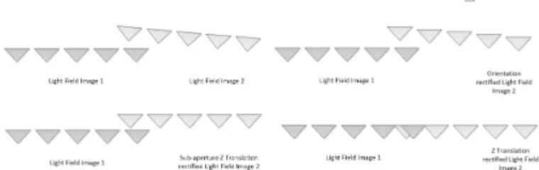
Figure 2: Light field rectification illustrated with virtual cam-eras capturing sub-aperture images. Second light field images are first rotated to compensate for the orientation difference of the light field cameras, then scaled to compensate for the z-axis translations.
to address this issue beforehand. Our approach is translate all sub-aperture such that they have the same location for identical feature points at the farthest distance. We use the epipolar image (EPI) slope based approach [12] to properly translate the sub-aperture images.
IV. LIGHT FIELD REGISTRATION
Our light field registration method consists of rectification and stitching steps. During rectification, all sub-aperture im-ages are compensated for rotation and translation so that they are on the same plane. During stitching, sub-aperture images are merged into a single light field. We now detail these steps. A. Rectification of sub-aperture images
Suppose we have two light fields decomposed into sub-aperture images; in Figure 2, we provide an illustration with virtual cameras capturing these aperture images. The sub-aperture images of the second light field are rotated and trans-lated with respect to the first light field sub-aperture images. While the translations differ, the rotation amount is same for all sub-aperture images. First, we would like to correct the orientations of the second light field sub-aperture images. The orientation can be estimated through the fundamental matrix [13] of any image pair from the first and second image sets. The standard approach is to extract and match the image features, such as eigen-features [14] or SURF [15], obtain the epipolar inliers, and estimate the fundamental matrix. We followed the procedure to estimate the fundamental matrix that minimizes the reprojection error, and then decomposed the essential matrix, which is obtained from the fundamental matrix, to obtain the rotation matrix [16]. Although any image pair is sufficient to obtain the rotation matrix, in order to minimize the effects of noise and other possible errors, we obtained the rotation matrix for every pair, averaged the rotation matrices, and ensured the final matrix is a rotation matrix by finding the closest rotation matrix in terms of the Frobenius norm [13].
The rotation matrix is applied to every sub-aperture image of the second light field to correct for the orientation. We then need to compensate for the z-axis translations (translations orthogonal to the image planes) within the second light field and between the first and second light fields. The effect of these translations is scale change between the images. Our approach to address this issue is to extract and match features, estimate homography matrix utilizing the RANSAC technique,
Figure 3: Final light field obtained by merging four light fields. and apply singular value decomposition to the homography matrix to get the scales. Because the scale is fixed between consecutive pairs of the second light field sub-aperture images, we take the geometric mean of the proper scales for robustness. As a result of the scale compensation, all light field sub-aperture images are placed on the same plane.
B. Light field stitching
After rectification, the light fields need to be merged into a single light field. This is done using the sub-aperture images, which now only differ in terms of spatial translations. The translations need to be estimated within each light field and between the light fields to properly place them in the final light field. We again used the feature extraction and matching approach to estimate the translation amounts. For four light fields, we followed the following steps:
1) Estimate the horizontal and vertical translation amounts between two neighboring sub-aperture im-ages within the each light field.
2) Estimate the translation amount between the first light field middle sub-aperture image and the every other light field middle sub-aperture image.
3) Combine all to obtain the translations among all sub-aperture images with respect to the first light field image origin.
Using these translations and linearly interpolating when a motion vector points to a non-integer location within a grid, a single light field is obtained. An example where four light fields are merged is shown in Figure 3.
V. RESULTS
In this section, we provide some experimental results obtained using the proposed algorithm. We used the Lytro light field camera and used the Matlab toolbox [11] to decode the light field. All implementations are done in Matlab, running on an i5 PC with 12 GB RAM. The rectification step for four light field data takes about 50 seconds, while the stitching step takes about 10 seconds. In this paper, we show a result, i.e., Figure 3, where the aperture size is extended. It is also possible to improve the spatial and angular resolution when the light fields overlap more.
A. Larger virtual aperture
One of the features of light field photography is the ability to digitally change focus after capture. With large aperture,
(a) Single light field. Focus is on the front object, the back object is zoomed-in.
(b) Four light fields merged. Focus is on the front object, the back object is zoomed-in.
(c) Single light field. Focus is on the back object, the front object is zoomed-in.
(d) Four light fields. Focus is on the back object, the front object is zoomed-in.
Figure 4: Out-of-focus blurs at different depths are shown. the refocusing effect becomes dramatic as the blur in focus regions would be large. On the other hand, the out-of-focus blur is small with small aperture. (The extreme case is a pinhole camera, where the out-of-focus blur even for a wide range of object distances is minimal.) In Figure 4, we show how the out-of-focus blur changes when we extend from single light field to merged light field.
B. Translation parallax
With the extension of light field image we also increase the baseline between the extreme sub-aperture images of the extended light field. This will also result in an increase of translation parallax. In our case, we have only shown the
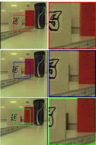
Figure 5: Translation parallax with the single light field and the extended light field. (Top) Leftmost sub-aperture image in the single light field and the extended light field. (Middle) Rightmost sub-aperture image in the single light field. (Bot-tom) Rightmost sub-aperture image in the extended light field. results for horizontal displacement. In our algorithm, the extension of light field is also possible in any displacement without the consideration of overlapping light field planes. The top image in Figure 5 gives the leftmost sub-aperture image in the single light field and the extended light field. The middle image in Figure 5 gives the rightmost sub-aperture in the single light field, whereas the bottom image in Figure 5 gives the rightmost sub-aperture in the extended light field. Figure 5 also gives zoomed-in regions from these images. The increase in the translational parallax is obvious as we can see more of an object behind a box in these zoomed-in regions.
C. Disparity map range and resolution
Microlens-array based light field cameras, such Lytro, have narrow baseline among the sub-aperture images. This limits the depth map estimation range and accuracy. By extending light field aperture, we essentially increase the angular range, and improve both depth map range and accuracy. In Figure 6, we show the disparity map for single and extended light fields. The disparity map, which can be converted to depth map, is obtained from the slopes of the epipolar images. As seen in this figure, we have a more continuous disparity map for the “ruler” in the image in the extended light field, which indicates an increase in accuracy. Also, the back part of the scene has better depth map for the extended light field, which indicates
(a) Disparity map with single light field.
(b) Disparity map with ex-tended light field.
Figure 6: Disparity map. larger depth estimation range.
VI. CONCLUSION AND FUTURE WORK
In this paper we presented a multi-view geometry based technique for light field registration and applied it to extend the angular range of light field. We demonstrated that angular extension improves depth estimation. With the proposed reg-istration technique, it is also possible to improve the angular and spatial resolution. As a future work, we will demonstrate how such a resolution enhancement improves the quality of images and capabilities of light field imaging.
REFERENCES
[1] G. Lippmann. Epreuves reversibles donnant la sensation du relief. J. Phys. Theor. Appl., 7(1):821–825, 1908.
[2] A. Gershun. The light field. J. of Mathematics and Physics, 18(1):51– 151, 1939.
[3] E. H. Adelson and J. R. Bergen. The plenoptic function and the elements of early vision. Massachusetts Institute of Technology, 1991. [4] M. Levoy and P. Hanrahan. Light field rendering. In Proc. ACM Conf.
Computer Graphics and Interactive Techniques, pages 31–42, 1996. [5] S. J. Gortler, R. Grzeszczuk, R. Szeliski, and M. F. Cohen. The
lumigraph. In Proc. ACM Conf. Computer Graphics and Interactive Techniques, pages 43–54, 1996.
[6] R. Ng. Digital light field photography. PhD thesis, Stanford University, 2006.
[7] Lytro, inc. https://www.lytro.com/.
[8] C. Birklbauer and O. Bimber. Panorama light-field imaging. In Computer Graphics Forum, volume 33, pages 43–52, 2014.
[9] X. Guo, Z. Yu, S. B. Kang, H. Lin, and J. Yu. Enhancing light fields through ray-space stitching. IEEE Trans. Visualization and Computer Graphics, PP(99):1–11, 2015.
[10] O. Johannsen, A. Sulc, and B. Goldluecke. On linear structure from motion for light field cameras. In Proc. IEEE Int. Conf. Computer Vision, pages 720–728, 2015.
[11] D. G. Dansereau, O. Pizarro, and S. B. Williams. Decoding, calibration and rectification for lenselet-based plenoptic cameras. In Proc. IEEE Int. Conf. Computer Vision and Pattern Recognition, pages 1027–1034, 2013.
[12] R. C. Bolles, H. H. Baker, and D. H. Marimont. Epipolar-plane image analysis: An approach to determining structure from motion. Int. J. Computer Vision, 1(1):7–55, 1987.
[13] R. Hartley and A. Zisserman. Multiple view geometry in computer vision. Cambridge University Press, 2003.
[14] J. Shi and C. Tomasi. Good features to track. In Proc. IEEE Int. Conf. Computer Vision and Pattern Recognition, pages 593–600, 1994. [15] H. Bay, A. Ess, T. Tuytelaars, and L. Van Gool. Speeded-up robust
features (surf). Computer Vision and Image Understanding, 110(3):346– 359, 2008.
[16] B. Horn. Recovering baseline and orientation from essential matrix. J. Opt. Soc. Am, 110, 1990.