* Corresponding author. Tel.: +90-274-443-4142 ; Fax: +90-274-265-2066 ; E-mail address: [email protected] (M. H. Saraçoğlu) ISSN: 2149-8024 / DOI: https://doi.org/10.20528/cjsmec.2020.03.006
Research Article
Stress and displacement analysis of perforated circular plates
Mustafa Halûk Saraçoğlu
a,*
, Fethullah Uslu
a, Uğur Albayrak
ba Department of Civil Engineering, Kütahya Dumlupınar University, 43100 Kütahya, Turkey b Department of Civil Engineering, Eskişehir Osmangazi University, 26480 Eskişehir, Turkey
ABSTRACT
Critical deflection and stress values of perforated circular plates under loads has an important role on the design criteria. For the perforated circular plates, the basic problem is determining how they have a perforation schema for the most suitable design. For this purpose, 10 different perforated circular plate models were pre-sented and their static analysis was studied. All of the models have the same open area percentage but different number of holes. In this way, it was more convenient to compare the results. The circular plates were analyzed under their self-weight and uniformly distributed load with different nine thickness to diameter ratios obtained based on Classical Plate Theory. In addition, two set of analyses have been performed on the circular plates for fixed supported and simply supported boundary conditions. As an example, for the 6th model critical displacement and stress values under
self-weight and under uniformly distributed load are investigated in detail. Designers of perforated circular plates can use the graphics presented in this study. The present study also purposes the shape optimization of thin circular perforated plates with round and staggered holes.
ARTICLE INFO Article history: Received 10 March 2020 Revised 16 May 2020 Accepted 3 June 2020 Keywords: Displacement Finite element method Perforated circular plates Static analysis
Stress
1. Introduction
Circular plates are common in many structures. They are used such as nozzle covers, end closures in pressure vessels, and bulkheads in submarines and airplanes, re-actors, heat exchangers, and distillation towers (Jawad, 2010).
There are many practical applications of perforated plates because of their advantages. They let flow of light and air. They have a resistant to high/low temperature and corrosion. They have light weight and they have a low cost. Also, in the architectural applications - office buildings, hospitals, educational establishments, air-ports, stations etc. - perforated plates are can be used as a ceilings, floors, dividers, walls etc. Many equipment as speakers, furniture, dryers, light fixtures etc. are made of perforated plates. Also daily use areas are very wide in-cluding electrical components, agricultural equipment, mining, food processing equipment, vehicles as well as other machines.
Studies about perforated circular plates with a serial solutions are not found in abundance in literature.
Timoshenko and Woinowsky-Krieger (1959), wrote the basic reference for plates and shells. Many authors have interested in bending of perforated plates. Harrop and Abdul-Karim (1967), investigated the deflections and stresses for circular plates with square pitch perfo-rations. The plates are subjected to uniform lateral pres-sure. They also compare the results with experimental results obtained by other investigators on three plate models. Murakami and Konishi (1982), studied about an elastic-plastic constitutive equation for transversely iso-tropic materials and as an application of the resulting con-stitutive equation, elastic-plastic bending of perforated circular plates is analyzed by modelling them by equiva-lent homogeneous transversely isotropic plates. Albayrak and Saraçoğlu (2011, 2018) and, Saraçoğlu and Albayrak (2016, 2017, 2018), were interested in plates with mul-tiple holes and published some research articles about their subject. Wu et al. (2003), present a mathematical
model of axisymmetric elastic/plastic perforated circu-lar plate bending and stretching is developed which ac-counts for through thickness yielding, through thickness variations in perforation geometry, elastic outer edge re-straint, and moderately large deflections. Atanasiu and Sorohan (2016), studied the displacements and stresses distribution in bending of perforated circular plate in their work using the finite element analysis (FEA) and experimentally by holographic interferometry. Azelmad et al. (2018), proposed a 2D typical model for the numer-ical simulation of the circular clamped perforated thin plates behavior in the elastic and elastoplastic domains. Their problem model is based on the real geometry of plates. The model takes into account different perfora-tion distribuperfora-tion patterns and ligament factors. Also it is then validated by experiments. Konieczny et al. (2020), presented an analysis of an isotropic circular axisym-metric perforated plate loaded with concentrated force applied in the geometric center of the plate using finite element software ANSYS. The results of numerical calcu-lations were compared and verified with experimental results.
In addition to theoretical studies, there are also stud-ies that carry out experimental studstud-ies about this subject takes place in the literature. Osweiller (1989), presented some curves about the effective elastic constants based on consistent theoretical and experimental results in his study. These curves allow one to determine accurate and confident effective elastic constants and they were some help to engineers concerned with the design of multi- perforated plates. Solar and Hill (1976), analyzed the perforated plates for tubesheet design in their study. And also a simple analytical expression is proposed to determinate the effective bending stiffness of a perfo-rated plate in the paper. Achtelik et al. (2008), presented a paper about elaborating the methodology of empirical studies in perforated plates centrally loaded by a con-centrated force. They also presented experimental re-sults to verify the mathematical model proposed in a companion paper.
There are a considerable number of studies that per-form dynamic analysis as well as static analysis. Civalek and Çatal (2003), studied numerical solution to static and free vibration analysis of thin circular and annular plates having various supports and load conditions are obtained by the method of Harmonic Differential Quad-rature (HDQ). Mishra and Das (1971), studied about free vibrations of isotropic nonhomogeneous circular plates and discussed the transverse vibration of nonhomogene-ous free circular plate in their paper. Jhung et al. (2006), investigated free vibration analysis of perforated plate and in their study the equivalent material properties of perforated plates are suggested by performing several fi-nite element analysis with respect to the ligament effi-ciencies. Jhung and Jo (2006), suggested the equivalent material properties of a perforated plate by performing several analyses with respect to ligament efficiencies. Jhung et al. (2009), studied about equivalent material properties of perforated structures. Lee and Chen (2011), in their paper theoretically derived the natural frequencies and natural modes of a circular plate with multiple circular holes and numerically determined.
Dinkar (2015), study about vibration analysis of perfo-rated plates in his doctoral thesis. Senjanovic et al. (2017), investigate the vibration analysis of thin circular plates with multiple openings. They use the assumed mode method and evaluate the results through their comparison with an analytical and finite element method solution. Jeong and Jhung (2017), have pre-sented free vibration analysis of partially perforated cir-cular plates with a triangular hole pattern and clamped boundary condition. They proposed a theoretical method and compare the results with finite element method solutions.
In this study, the effect of perforation pattern in per-forated circular plates is investigated. For this purpose, ten perforated plate models were produced and stati-cally analyzed under their self-weight. The finite element software ANSYS workbench was used to analyze the de-flection behavior of thin circular plates with open holes in bending, and put forth a suitable perforation pattern for a perforated circular plate was proposed.
2. Material and Methods
Deformations and stresses in a plates are calculated by using a plate theory. Various plate theories have been developed since 19th century. In engineering two of them are widely used. One of them is named Kirchhoff–Love plate theory and also named as Classical Plate Theory (CPT). The other is named as Mindlin–Reissner plate the-ory and also named as First-order Shear Deformation Plate Theory (FSDPT). Every theory has different as-sumptions. In this study perforated circular plates are analyzed using CPT. In this theory the following kine-matic assumptions are made:
Straight lines normal to the mid-surface remain straight after deformation.
Straight lines normal to the mid-surface remain nor-mal to the mid-surface after deformation.
The thickness of the plate does not change during a deformation.
In CPT, thickness to width ratio of a plate structure is have to be between 1/150 and 1/20.
The equations developed with reference to Cartesian coordinates are not convenient for the analysis of circu-lar plates (Bhaskar et al., 2014). Therefore, the differen-tial equations for the bending of a rectangular plate have to be transform to the polar coordinates for circular plates.
For the analysis of stress and displacement distribu-tion of circular plates under loads, the derived differen-tial equations of circular plates must have to be solved. These equilibrium equations of plates was made around 1900 by Love. These investigations were made for vari-ous boundary conditions and loadings.
When the load is symmetrically on the axis perpen-dicular to the circular plate through its center, the de-flection surface is bent also symmetrically. So that, all points which have equal distance from the center of the plate the deflections will be the same as can be seen at Fig. 1.
Fig. 1. Deflection of a circular plate.
The governing differential equation of a circular plate in cylindrical coordinates is given in Eq. (1):
1 r d dr
{r
d dr[
1 r d dr(r
dw dr)]} =
q D (1)In this equation w is the deflection of the plate, r is the radius coordinate of the circular plate, q is the intensity of loading and D is the flexural rigidity of the plate for-mulated at Eq. (2) dependent to E modulus of elasticity, υ Poisson’s ratio and h plate thickness.
𝐷 = 𝐸ℎ3
12(1−𝜈2) (2)
Considered coordinates for circular plates with fixed supported and simply supported boundary conditions are shown in Fig. 2.
(a) Fixed supported (b) Simply supported
Fig. 2. Coordinates of a circular plate. 3. Numerical Applications
For demonstrating the differences between perfora-tion patterns ten models were produced systematically
as shown in Fig. 3. Firstly, a non-perforated circular plate with no holes is taken as a reference plate. These models were subjected to bending analysis under their self weights.
Fig. 3. Models of perforated circular plates. dr r B w O x z x y z x z x y x r x y O a z r x y O a z
Stress and displacement analysis of these models in-vestigated and mid-point deflections and stresses are calculated. Circular plates are considered as they are thin plates. Nine different thickness to diameter ratio of these thin plate structures is taken into account as 2/300, 3/300, 4/300, 5/300, 6/300, 8/300, 10/300, 11/300 and 14/300 respectively. The solutions were developed for boundary conditions of simply supported and fixed supported.
The circular plate models are assumed to have the ra-dius of 150 mm and made of steel material. The material parameters of the steel plates are assumed as shown in Table 1.
Table 1. Material properties of the perforated steel plate.
Property Value
Young's modulus, E (GPa) 200 Poisson's ratio, υ 0.3 Mass density, ρ (kg/m3) 7850
Shell181 has a capability for analyzing thin to moder-ately-thick shell structures. It is defined by four nodes. There are six degrees of freedom at each node as: rota-tions about the x, y and z axes, and translarota-tions in the x, y and z directions.
Triangular free mesh is used in free meshing opera-tions. In the example models 1mm finite element mesh size is used.
After preprocessing the problem in the program, static analysis was performed and the results of defor-mations and stresses were obtained from the program.
Stress output for SHELL181 element is as follows: σx is normal stress due to X axis (SX)
σy is normal stress due to Y axis (SY)
τxy is shear stress (SXY)
Number of holes, radius of the circular holes and total hole area is dependent to the model number n. In all of the perforated circular plate models % open area is the same as shown in Table 2.
Analyses of these models ANSYS software was used. This finite element software has various elements in the ele-ment library for static and dynamic analyses. For this study Shell181 is the most suitable element for the problem. Table 2. Total hole areas for the models.
Model No Number of holes Radius Total hole area
0 0 0.0000 0*π*02 1 4 37.5000 4*π*37.50002 2 16 18.7500 16*π*18.75002 3 36 12.5000 36*π*12.50002 4 64 9.3750 64*π*9.37502 5 100 7.5000 100*π*7.50002 6 144 6.2500 144*π*6.25002 7 196 5.3571 196*π*5.35712 8 256 4.6875 256*π*4.68752 9 324 4.1667 324*π*4.16672 10 400 3.7500 400*π*3.75002 . . . . . . . . . . . . n (2*n)2 R/(4*n) (π*R2)/4
4. Results and Discussion
Although the plate models in this study have the same arrangement they have different number of holes. The circular plates examined to different number of holes as 4, 16, 36, 64, 100, 144, 196, 256, 324, 400, respectively and radius and locations are also different. As seen from the Table 2, % open areas of the models are exactly same. Analyze results evaluate how the perforated circular would perform under self-weight. The results can be ex-amined under two headings, namely displacements and stresses.
4.1. Displacements under self-weight
Fig. 4 shows comparison of mid-point deflections for fixed supported and simply supported non-perforated and perforated circular plates according to ten models with different nine thickness to diameter ratios obtained by ANSYS with solutions based on CPT.
It can be seen from the Fig. 4 that mid-point deflec-tions of the circular plates have almost the same value for the models greater than 6th model.
Critical displacements for non-perforated and perfo-rated (6th model) circular plates are given in Table 3.
Fig. 4. Midpoint deflections of fixed supported and simply supported non-perforated and 10 perforated circular plate models according to thickness to diameter ratios.
Table 3. Critical displacements of the plates under self-weights (mm).
h/D Fixed Supported Simply Supported
non-perforated perforated non-perforated perforated
2/300 -0.008318 -0.011111 -0.033893 -0.047570 3/300 -0.003701 -0.004989 -0.015067 -0.021177 4/300 -0.002085 -0.002833 -0.008478 -0.011930 5/300 -0.001337 -0.001828 -0.005429 -0.007647 6/300 -0.000930 -0.001280 -0.003772 -0.005318 8/300 -0.000526 -0.000730 -0.002125 -0.003000 10/300 -0.000339 -0.000473 -0.001362 -0.001925 11/300 -0.000282 -0.000393 -0.001127 -0.001593 14/300 -0.000176 -0.000247 -0.000698 -0.000988
Displacement values for all points of fixed and simply supported perforated (6th model) circular plate for D/h=150 under self-weights is shown in Fig. 5.
4.2. Displacements under uniformly distributed load Displacements under uniformly distributed q=1kN/m2 load has been performed on the two set of plates for fixed supported and simply supported non-perforated and 6th model perforated circular plates.
The critical displacements of the circular plates loaded with uniformly distributed load are shown in
Ta-ble 4 with two support conditions. The maximum deflec-tion is occurs at the midpoint of the circular plate and smaller than the thickness of the plate.
4.3. Stresses under self-weight
Stress distribution for the perforated circular holes under self-weights is more complex than the deflection distributions.
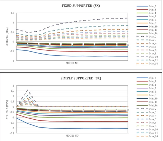
In Fig. 6, minimumSX and maximumSX stress values of non-perforated circular plate and ten models of fixed and simply supported perforated circular plates are shown.
-0.012 -0.010 -0.008 -0.006 -0.004 -0.002 0.000 0 1 2 3 4 5 6 7 8 9 10 M ID -P O INT D EF LE CT IO NS ( m m ) MODEL NO FIXED SUPPORTED 2/300 3/300 4/300 5/300 6/300 8/300 10/300 11/300 14/300 -0.050 -0.040 -0.030 -0.020 -0.010 0.000 0 1 2 3 4 5 6 7 8 9 10 M ID -P O INT D EF LE CT IO NS ( m m ) MODEL NO SIMPLY SUPPORTED 2/300 3/300 4/300 5/300 6/300 8/300 10/300 11/300 14/300
MinimumSY and maximumSY stress values of non-perforated circular plate and ten models of non-perforated circular plates are shown in Fig. 7.
MinimumSXY and maximumSXY stress values of non-perforated circular plate and ten models of non-perforated circular plates are shown in Fig. 8.
As an example stress distribution of reference (non-perforated) and 6th model (perforated) plate for D/h=150 is shown in Fig. 9. In the example variation of stresses along line from point (0,0,0) to point (150,0,0) for perforated and non-perforated reference plates un-der their self-weights are given.
Similar to fixed supported plates, variation of stresses for simply supported circular plates are also given in Fig. 9.
From the graphs it can be inferred that there are large stress jumps on the perimeters of the holes.
The critical stresses of the circular plates under self-weights are shown in Table 5 with two support condi-tions. Circular plates are taken as non-perforated and as an example for 6th perforated model.
Stress values for all points of fixed and simply sup-ported perforated (6th model) circular plate for D/h=150 under self-weights is shown in Fig. 10.
fixed supported simply supported
Fig. 5. Displacement values of fixed and simply supported perforated (6th model) circular plate for D/h=150 under self-weights.
Fig. 6. MinimumSX and MaximumSX stress values of fixed supported and simply supported non-perforated and 10 perforated circular plate models.
-1 -0.5 0 0.5 1 1.5 0 1 2 3 4 5 6 7 8 9 10 ST R ES SE S (M Pa ) MODEL NO
FIXED SUPPORTED (SX) Min_2
Min_3 Min_4 Min_5 Min_6 Min_8 Min_10 Min_11 Min_14 Max_2 Max_3 Max_4 Max_5 Max_6 Max_8 Max_10 Max_11 Max_14 -2.5 -2 -1.5 -1 -0.5 0 0.5 1 1.5 2 0 1 2 3 4 5 6 7 8 9 10 ST R ES SE S (M Pa ) MODEL NO
SIMPLY SUPPORTED (SX) Min_2
Min_3 Min_4 Min_5 Min_6 Min_8 Min_10 Min_11 Min_14 Max_2 Max_3 Max_4 Max_5 Max_6 Max_8 Max_10 Max_11 Max_14
Table 4. Critical displacements of the plates loaded with uniformly distributed load (mm).
h/D Fixed Supported Simply Supported
non-perforated perforated non-perforated perforated
2/300 -0.054028 -0.072168 -0.220140 -0.308970 3/300 -0.016025 -0.021603 -0.065242 -0.091695 4/300 -0.006770 -0.009199 -0.027534 -0.038743 5/300 -0.003473 -0.004750 -0.014104 -0.019866 6/300 -0.002014 -0.002771 -0.008166 -0.011513 8/300 -0.000854 -0.001185 -0.003450 -0.004871 10/300 -0.000441 -0.000615 -0.001770 -0.002501 11/300 -0.000332 -0.000465 -0.001331 -0.001882 14/300 -0.000164 -0.000230 -0.000648 -0.000917
Fig. 7. MinimumSY and MaximumSY stress values of fixed supported and simply supported non-perforated and 10 perforated circular plate models.
Fig. 8. (continued) -1 -0.5 0 0.5 1 1.5 0 1 2 3 4 5 6 7 8 9 10 ST R ES SE S (M Pa ) MODEL NO
FIXED SUPPORTED (SY) Min_2
Min_3 Min_4 Min_5 Min_6 Min_8 Min_10 Min_11 Min_14 Max_2 Max_3 Max_4 Max_5 Max_6 Max_8 Max_10 Max_11 Max_14 -2.5 -2 -1.5 -1 -0.5 0 0.5 1 1.5 2 0 1 2 3 4 5 6 7 8 9 10 ST R ES SE S (M Pa ) MODEL NO
SIMPLY SUPPORTED (SY) Min_2
Min_3 Min_4 Min_5 Min_6 Min_8 Min_10 Min_11 Min_14 Max_2 Max_3 Max_4 Max_5 Max_6 Max_8 Max_10 Max_11 Max_14 -0.8 -0.6 -0.4 -0.2 0 0.2 0.4 0.6 0.8 0 1 2 3 4 5 6 7 8 9 10 ST R ES SE S (M Pa ) MODEL NO
FIXED SUPPORTED (SXY) Min_2Min_3
Min_4 Min_5 Min_6 Min_8 Min_10 Min_11 Min_14 Max_2 Max_3 Max_4 Max_5 Max_6 Max_8 Max_10 Max_11 Max_14
Fig. 8. MinimumSXY and MaximumSXY stress values of fixed supported and simply supported non-perforated and 10 perforated circular plate models.
Fig. 9. Stress values of fixed supported and simply supported non-perforated and perforated (6th model) circular plate for D/h=150.
Table 5. Critical stresses of the plates under self-weights (MPa).
Fixed Supported Simply Supported
Minimum Maximum Minimum Maximum
non- perforated perforated non- perforated perforated non- perforated perforated non- perforated perforated SX -0.422180 -0.756420 0.644680 1.104500 -0.004581 0.012353 -1.071700 -2.080700 SY -0.422170 -0.757280 0.644880 1.106200 -0.004164 0.008235 -1.071700 -2.086300 SXY -0.226080 -0.535380 0.226080 0.535380 0.226120 1.077800 -0.226120 -1.077800 -1.5 -1 -0.5 0 0.5 1 1.5 0 1 2 3 4 5 6 7 8 9 10 ST R ES SE S (M Pa ) MODEL NO
SIMPLY SUPPORTED (SXY) Min_2
Min_3 Min_4 Min_5 Min_6 Min_8 Min_10 Min_11 Min_14 Max_2 Max_3 Max_4 Max_5 Max_6 Max_8 Max_10 Max_11 Max_14 -0.8 -0.6 -0.4 -0.2 0 0.2 0.4 0.6 0.8 0 20 40 60 80 100 120 140 160 ST R ES SE S (M Pa ) R FIXED SUPPORTED SX_P SY_P SXY_P SX_NP SY_NP SXY_NP -2.5 -2 -1.5 -1 -0.5 0 0.5 0 20 40 60 80 100 120 140 160 ST R ES SE S (M Pa ) R SIMPLY SUPPORTED SX_P SY_P SXY_P SX_NP SY_NP SXY_NP
fixed supported
simply supported
Fig. 10. Stress values of fixed and simply supported perforated (6th model) circular plate for D/h=150 under self-weights.
4.4. Stresses under uniformly distributed load Stresses under uniformly distributed q=1kN/m2 load has been performed on the two set of plates for fixed
supported and simply supported non-perforated and 6th model perforated circular plates.
The critical stresses of the plates loaded with uni-formly distributed load can be seen in Table 6.
Table 6. Critical stresses of the plates loaded with uniformly distributed load (MPa).
Fixed Supported Simply Supported
Minimum Maximum Minimum Maximum
non- perforated perforated non- perforated perforated non- perforated perforated non- perforated perforated SX -2.742 -4.9129 4.1872 7.1739 -0.029753 0.080234 -6.9607 -13.514 SY -2.742 -4.9186 4.1885 7.1847 -0.027043 0.053483 -6.9607 -13.551 SXY -1.4684 -3.4773 1.4684 3.4773 1.4686 7.0004 -1.4686 -7.0004 5. Conclusions
In this paper, the mid-point deflection and stress val-ues of the perforated circular plate under self-weights and under uniformly distributed load with the influence of holes was calculated and analyzed. Series of models have been produced for investigating the stresses and displacements of perforated circular plates.
The results obtained can be listed as follows:
In all of the perforated circular plate models % open area is the same as shown in Table 2.
Problems were analyzed by using finite element anal-ysis software ANSYS Workbench.
Displacement and stress distribution of perforated circular plate under self-weights and under distrib-uted q=1kN/m2 load was separately analyzed and re-sults are presented as tables and graphics.
Critical deflection and stress values has an important role on the design of perforated circular plates. The deflections for the simply supported perforated
circular plates is approximately 4.3 times higher than those fixed supported perforated circular plates.
The results obtained for nine different diame-ter/thickness values within the limits of thin plate ac-ceptance showed approximately the same behavior. The variation of the deflection and stress values are
getting asymptotic after the 6th model.
Critical displacement values of perforated circular plate under self-weights for fixed supported is 0.011111 mm and for simply supported is 0.047570 mm.
Critical SX values of perforated circular plate under self-weights for fixed supported is 1.104500 MPa and for simply supported is 2.080700 MPa.
Critical SY values of perforated circular plate under self-weights for fixed supported is 1.106200MPa and for simply supported is 2.086300 MPa.
Critical SXY values of perforated circular plate under self-weights for fixed supported is 0.535380 MPa and for simply supported is 1.077800 MPa.
Critical displacement values of perforated circular plate under distributed load for fixed supported is 0.072168 mm and for simply supported is 0.308970 mm.
Critical SX values of perforated circular plate under distributed load for fixed supported is 7.173900 MPa and for simply supported is 13.514000 MPa.
Critical SY values of perforated circular plate under distributed load for fixed supported is 7.184700 MPa and for simply supported is 13.551000 MPa.
Critical SXY values of perforated circular plate under distributed load for fixed supported is 3.477300 MPa and for simply supported is 7.000400 MPa.
When the number of holes increases, deflection and stress values are getting asymptotic.
Designers of perforated circular plates can take into account these midpoint deflections by using these graphics.
As a result, the present study purposes the shape op-timization of thin circular perforated plates with round and staggered holes. And perforation schemas can also be developed by different optimization techniques. REFERENCES
Achtelic H, Gasiak G, Grzelak J (2008). Strength tests of axially symmet-ric perforated plates for chemical reactors: Part 2-Experiments. In-ternational Journal of Pressure Vessels and Piping, 85, 257–264. Albayrak U, Saraçoğlu MH (2011). Analyzing of thin square plates with
multiple circular holes. International Symposium on Advances in Ap-plied Mechanics and Modern Information Technology 2011 (ISAAM&MIT’11), Baku, Azerbaijan, 79–83.
Albayrak U, Saraçoğlu MH (2018). Analysis of regular perforated metal ceiling tiles. International Journal of Engineering and Technology, 10(6), 440–46.
Atanasiu C, Sorohan S (2016). Displacements and stresses in bending of circular perforated plate. IOP Conference Series: Materials Science and Engineering, 147(1).
Azelmad E, Salmi A, El Kennassi E, Bousshine L (2018). Elastoplastic behavior analysis of clamped circular perforated thin plates. IOSR Journal of Mechanical and Civil Engineering, 15(2), 23–37. Bhaskar K, Varadan R (2014). Plates: Theories and Applications. Wiley
Online Library, ISBN:9781118893876.
Civalek Ö, Çatal H (2003). Linear static and vibration analysis of circu-lar and annucircu-lar plates by the harmonic differential quadrature (HDQ) method. Journal of Engineering and Architecture Faculty of Eskişehir Osmangazi University, XVII(1), 43–71.
Dinkar MK (2015). Vibration Analysis of Perforated Plates. Ph.D thesis, Birla Institute of Technology and Science, Pilani.
Harrop J, Abdul-Karim RM (1967). Stresses and deflections in circular plates with square pitch perforations. Nuclear Engineering and De-sign, 6(5), 431–39.
Jawad MH (2010). Design of Plate and Shell Structures: Bending of Cir-cular Plates. ASME Press, ISBN: 0791801993.
Konieczny MM, Achtelik H, Gasiak G (2020). Finite element analysis (FEA) and experimental stress analysis in circular perforated plates loaded with concentrated force. Frattura ed Integrita Strutturale, 14(51), 164–173.
Kyeong-Hoon J, Myung-Jo J (2017). Free vibration analysis of partially perforated circular plates. Procedia Engineering, 199, 182–87. Lee WM, Chen JT (2011). Free vibration analysis of a circular plate with
multiple circular holes by using indirect BIEM and addition theo-rem. Journal of Applied Mechanics, Transactions ASME, 78(1), 0110151–510.
Mishra DM, Das AK (1971). Free vibrations of an isotropic nonhomo-geneous circular plate. AIAA Journal, 9(5), 963–64.
Murakami S, Konishi K (1982). An elastic-plastic constitutive equation for transversely isotropic materials and its application to the bend-ing of perforated circular plates. International Journal of Mechanical Sciences, 24(12), 763–75.
Myung J, Hwan Y, Ho Y (2009). Equivalent material properties of per-forated structure for free vibration analysis. Modal Analysis, (SMiRT 20), 1–8.
Myung Jo J, Jong Chull J (2006) Equivalent material properties of per-forated plate with triangular or square penetration pattern for dy-namic analysis. Nuclear Engineering and Technology, 38(7), 689–96. Myung-Jo J, Jong Chull J, Kyeong Hoon J (2006). Free vibration analysis
of perforated plate submerged in fluid. Journal of Mechanical Sci-ence and Technology, 20(9), 1323–38.
Osweiller F (1989). Evolution and synthesis of the effective elastic con-stants concept for the design of tubesheets. Journal of Pressure Ves-sel Technology, Transactions of the ASME, 111(3), 209–17. Saraçoğlu MH, Albayrak U (2016). Linear static analysis of perforated
plates with round and staggered holes under their self-weights. Re-search on Engineering Structures & Materials, 2(1), 39–47. Saraçoğlu MH, Albayrak U (2017). Computational analysis of
perfo-rated rectangular thin plates. 2nd International Conference on Civil and Environmental Engineering, Nevşehir, Turkey, 1864.
Saraçoğlu MH, Albayrak U (2018). Analysis of regular perforated rec-tangular plates. 5th International Conference on Civil and Urban En-gineering (ICCUE 2018), Barcelona, Spain, 47.
Senjanović I, Hadžić N, Vladimir N (2017). Vibration analysis of thin circular plates with multiple openings by the assumed mode method. Proceedings of the Institution of Mechanical Engineers Part M: Jour-nal of Engineering for the Maritime Environment, 231(1), 70–85. Solar AI, Hill WS (1976). Effective bending properties for stress
analy-sis of rectangular tubesheets. American Society of Mechanical Engi-neers (Paper) (76-WA/Pwr-1), 365–70.
Timoshenko S, Woinowsky-Krieger S (1959). Theory of Plates and Shells. McGraw-Hill Inc.
Wu DJ, Peddieson GR, Rochelle SG (2003). Large axisymmetric defor-mations of elastic/plastic perforated circular plates. Journal of Pres-sure Vessel Technology, Transactions of the ASME, 125(4), 357–64.