T.C.
ISTANBUL AYDIN UNIVERSITY INSTITUTE OF GRADUATE STUDIES
POWER QUALITY CONTROL & ECONOMIC OPERATION IN PV-BES-DG IN AUTONOMOUS
THESIS
Danish Ali
Department of Electrical and Electronics Engineering Electrical and Electronics Engineering Program
T.C.
ISTANBUL AYDIN UNIVERSITY INSTITUTE OF GRADUATE STUDIES
POWER QUALITY CONTROL & ECONOMIC OPERATION IN PV-BES-DG IN AUTONOMOUS
THESIS
Danish Ali (Y1813.300029)
Department of Electrical and Electronics Engineering Electrical and Electronics Engineering Program
Advisor: Prof. Dr Murtaza FARSADİ
DECLARATION
I hereby declare that all information in this thesis document has been obtained and presented in accordance with academic rules and ethical conduct. I also declare that, as required by these rules and conduct, I have fully cited and referenced all material and results, which are not original to this thesis.
FOREWORD
After thanks to Allah our creator, I would like to thank my mother and my father who raised me to become a good person. They were patient during my mistakes and my bad times and helped me in all times and everything I have accomplished is because of their effort. I hope I can make them happy and return even some of what they gave me during their whole lives.I would like to thank my thesis advisor Dr. Murtaza Farsadi for his guidance, support, and help during my work in the thesis. I thank him for everything I learned from him.I thank all my teachers starting from my school time until today as they had great influence on me and made me love education and I hope I can become one day a good teacher as they were.
June, 2020 Danish Ali
TABLE OF CONTENT
Page
FOREWORD ... iv
TABLE OF CONTENT ... v
ABBREVIATIONS ... vii
LIST OF FIGURES ... viii
ABSTRACT ... x ÖZET ... xi 1. INTRODUCTION ... 1 1.1 Purpose ... 1 1.2 Problem Statement: ... 1 1.3 Literature Review ... 2 1.3.1 Definitions of Micro-Grid: ... 2
1.4 Micro-Grid & its Requirements: ... 3
1.5 Operational modes of Micro-Grid ... 4
1.5.1 Autonomous or Islanded Mode: ... 4
1.5.2 Grid Connected Mode: ... 6
1.6 Overview: ... 6
1.6.1 Utility or Community Micro-Grids: ... 7
1.6.2 Industrial or Commercial Micro-Grids: ... 7
1.6.3 Campus or Institutional Micro-Grids: ... 7
1.6.4 Military Micro-Grids: ... 8
2. SYSTEM CONFIGURATION AND COMPONENTS ... 1
2.1 Renewable Resources ... 2
2.2 Types of Renewable Energy Resources ... 2
2.2.1 Solar Energy System: ... 3
2.2.2 Photo-Voltaic Arrays or Solar Panels: ... 4
2.2.3 Solar cell ... 4
2.2.4 PV Cell Characteristic at different Irradiances ... 5
2.3 Mathematical Modeling of PV ... 7
2.4 Energy Storage System (ESS): ... 9
2.5 Battery Controller ... 12
2.6 State of charge (SOC): ... 12
2.7 Diesel Generator: ... 13
2.8 AC DCConverters: ... 14
2.9 Buck-Boost Converters: ... 15
3. PROPOSED SYSTEM &METHODOLOGY: ... 17
3.1 Photo-Voltaic System Operation: ... 18
3.2 Operation of Battery Storage System ... 20
3.3 Operation of inverter System ... 21
3.4 Operation of MPPT System: ... 23
3.5 Operation of Active harmonic filter System: ... 24
4. EXPERIMENTAL RESULTS: ... 29
5. CONCLUSİONS & FUTURE RECOMMENDATİONS: ... 38
REFERENCES ... 39
ABBREVIATIONS
PWM : Pulse Width Modulation
DC : Direct Current
AC : Alternating Current
PCC : Point of Common Coupling DERS : Distributed Energy Resources PSO : Particle Swarm Optimization PID : Proportional Integral Derivative
MG : Microgrid
DERs : Distributed Energy Resources EMS : Energy Management System ESUs : Energy Storage Units
THD : Total Harmonic Distortion H.O : Harmonic Order
PV : Photovoltaic Panels DG : Distributed Generation DG : Diesel Generator
MS : Microsystem
ESS : Energy Storage System SC : Solar Cell
TSR : Tip Speed Ratio Control PSF : Power Signal Feedback HCS : Hill Climb Search Based SOC : State of Charge
LIST OF FIGURES
Page
Figure 1.1: General Layout of Micro-Grid ... 2
Figure 1.2: General Layout of Autonomous or Islanded Mode ... 5
Figure 1.3: General Layout of Grid Connected Mode ... 6
Figure 1.4: General Networked Structure of Micro-Grid ... 8
Figure 2.1: Block Diagram of Proposed System... 1
Figure 2.2: Depiction of Proposed System ... 2
Figure 2.3: Types of Renewable Resources ... 2
Figure 2.4: Home based Solar Energy System ... 3
Figure 2.5:Characteristic of VI at different irradiation ... 5
Figure 2.6:characteristics of Power of the PV cell with different irradiances value .. 5
Figure 2.7: characteristics ofPower of PV cell at different values of Temprature ... 6
Figure 2.8: characteristics of VI of Solar cell with different temperature ... 6
Figure 2.9: Equivalent Circuit of PV Cell ... 7
Figure 2.10: PV array with multiple strings ... 8
Figure 2.11: Application Purposes of Energy storage system. ... 10
Figure 2.12: Detailed claasifications of energy storage technologies. ... 11
Figure 2.13: Typical Configurations of Energy Storage System ... 12
Figure 2.14:Diesel Generator ... 13
Figure 2.15: Configurations of 3 Phase Biderctional AC DC Converter ... 14
Figure 2.16: General circuit of Buck-Boost Converter ... 15
Figure 2.17: Simulink circuit of Buck-Boost Converter with P&O MPPT Algorithm ... 16
Figure 3.1: Matlab Simulink Model of Propsed System ... 17
Figure 3.2: Solar power, MPPT, Battery storage and Inverter system simulink circuit. ... 18
Figure 3.3: PV System in Simulink ... 19
Figure 3.4: Power, Voltage and Current generated by solar arrays ... 19
Figure 3.5: Battery Storage System in Simulink... 21
Figure 3.6: 3 Phase Inverter System in Simulink. ... 22
Figure 3.7: MPPT Circuit in Simulink. ... 23
Figure 3.8: Circuit of Active Harmonics System in Simulink. ... 26
Figure 3.9: Control Layout System in Simulink. ... 26
Figure 4.1: PV voltage, Current and power outputs. ... 29
Figure 4.2: Battery sharing power in the absence of PV. ... 29
Figure 4.3: MPPT input & Output voltage. ... 30
Figure 4.4: Battery SOC Charging Discharging, load current and voltage, ... 30
Figure 4.5: Rectifier load only Load side ... 31
Figure 4.6: Rectifier load only Source side ... 31
Figure 4.7: Rectifier load +R Load ... 32
Figure 4.9: Source Voltage, current and load current wave forms ... 33
Figure 4.10: RL Load current Harmonics Load Side ... 33
Figure 4.11: RL Load current Harmonics Load Side ... 34
Figure 4.12: Rectifier and RL Load THDs, THD of source current ... 34
Figure 4.14: Rectifier and RC Load THDs, THD of source current ... 35
Figure 4.15: Voltage, source current and load current wave forms @RLC LOAD . 36 Figure 4.16: THD of RLC Load at Load Side ... 37
POWER QUALITY CONTROL & ECONOMIC OPERATION IN PV-BES-DG IN AUTONOMOUS
ABSTRACT
In this thesis, an autonomous renewable system which is backed-up by diesel generator is proposed which maintain the system’s economic performance and power quality within permissible limits of IEEE 519 standard. The system feeds Non linear loads, which will be primarily fed by Photovoltaic system in the presence of sun light and by battery energy storage, also there is diesel generator available which is operated in ON/OFF state,the generator will not be running in continuous mode, rather it will work in ON/OFF mode to maintain the system operation economic, Minimum fuel cost and maximum fuel efficiency will be obtained by maintaing the system free from harmonics which will be present in the presence of non linear load. Active filter system will be deployed to the system which will counter the unknown harmonics so that less reactive power and harmonicssustain in the system. The coordinated control among Bidirectional Buck-Boost converter and Voltage source controller will obtain the multiple objectives like maximum power point track (MPPT), battery state of charge (SoC),maximum fuel efficiency and minimum running cost while meeting the minimum critical load demands in the system.
Key Words: PV-BES-DG(PhotoVoltaic-Battery Energy Storage-Diesel Generator),
PV-BES-DG TABANLI ÖZERK SISTEMDE GÜÇ KALITESI KONTROL VE EKONOMIK OPERASYON
ÖZET
Bu tezde, dizel jeneratör tarafından yedeklenmiş özerk bir yenilenebilir bir sistem, IEEE 519 standardının izin verilen sınırları içinde sistemin ekonomik performansı ve güç kalitesini koruyan önerilir. Sistem, güneş ışığı ve pil enerji depolamasında varlıkta fotovoltaik sistem tarafından öncelikle beslenmemiş olmayan doğrusal yükleri besler, ayrıca açık / kapalı devlette işletilen dizel jeneratörü var, jeneratör sürekli modda çalışmaz, oldukça oldukça çalıştırmak için sistem / amformal modda çalıştırmak için ekonomik, minimum yakıt maliyeti ve maksimum yakıt verimliliği, lineer yük varlığında bulunacak şekilde harici montajı sağlayarak sağlanacak. Aktif filtre sistemi, bilinmeyen harmoniği sayacak sistem, sistemdeki az daha reaktif güç ve harmonikssusta olacak şekilde sürdürülebilir. İki yönlü buck-artırıcı dönüştürücü ve voltaj kaynak kontrol cihazı arasında koordine edilmiş kontrol, maksimum güç noktası parçasının (MPPT), pil durumu (SOC), maksimum yakıt verimliliği ve minimum koşul maliyeti gibi birden fazla hedef elde edilir. Sistemdeki minimum kritik yük taleplerini karşılayacaktır.
Anahtar Kelimeler: PV-BES-DG (Photovoltaic-Pil Enerji Depolama-Dizel
1. INTRODUCTION
1.1 Purpose
The purpose of this thesis is to rely maximum on the renewable resources so that the conventional generation methods like coal fired generation, diesel generation, steam turbines generation and all other non-environmental friendly and high running cost generation methods can be replaced by implementing the naturally available free resources which are also environmental friendly. No air pollution or sound pollution spread with the photovoltaic system, also another aspect of this study is to mitigate the harmonics in the system when non-linear loads are present in the system so that all the available power can be utilized in effective work done and least reactive power sustain in the system and hence the performance of the system will be more smooth and efficient.
1.2 Problem Statement:
In Power systems specifically in renewable systems which are backed up by some conventional resources like diesel generators, its very important to deal with harmonics and reactive power which are generated in the system when Non-linear loads are connected to the system, in order to maintain system economic and fuel efficient when system is being operated on diesel generator so the full rated KVA will be available for load rather than wasting energy in reactive power and harmonics, because in the presence of these parameters the efficiency of the system and economic operation of the system does not remain optimal so we need to mitigate harmonics from the system and reduce the reactive power. The other part which has to be dealt in this thesis is coordinated control among different subsytems, in first the, first priorty is to obtain power from Photo-voltaic system, the extra power demand will be obtained using battery energy storage and diesel generator, for this operation an algorithm is needed to be designed.
1.3 Literature Review
A Microgrid is a compact unit which is consist of multiple loads and local Distributed generators which operates in two modes Grid connected mode and the Islanded or autonomous mode. In grid connected mode the Microgrid is linked with main grid and it is part of the interconnected system, but in autonomous mode it is self dependent, energy is generated by local DGsand there may be backup conventional generation method is available which may be diesel engine generator.In this thesis we will explore the microgrid in islanded or autonomous mode.
Micro-Grid:
Figure 1.1: General Layout of Micro-Grid 1.3.1 Definitions of Micro-Grid:
There are many definitions of Micro-Grid defined by different institutes; some of them are as under,
• An integrated ES (energy system) comprising of distributed ER(energy resources) and different electrical loads running as a unified, independent grid either working in parallel to the existing utility power-grid or working as islanded system.
• The IEEE(Institute of Electrical and Electronics Engineers) has described DR(distributed resources)as the sources of generation of electric power which aren’t directly linked with high power transmission line system. Distributive resourcescontain generators & energy storage systems. While DG is defined as, “ 28 generation facilities of electrical energy,linked with an area EPS electric power system with a PCC(point of common coupling) as subunit of distributive resource (DR) , EPS is actually a compact unit which supply the Electrical Power to the loads.
• IEA (International Energy Agency) views Distributive generators (DG) as the units which are producing electrical power on a consumer site, or within local distribution utilities &feeding electrical power directly to local distribution system.
• However, most accepted definition by Dr. Robert H. Lasseter , Professor and Principle Research Scientist, University of Wisconsin, Madison, is ―The Consortium for Electric Reliability Technology Solutions (CERTS) MicroGrid concept assumes an aggregation of loads and microsources operating as a single system providing both power and heat. The majority of the microsources must be power electronic based to provide the required flexibility to insure operation as a single aggregated system. This control flexibility allows the CERTS Micro-Grid to present itself to the bulk power system as a single controlled unit that meets local needs for reliability and security.
1.4 Micro-Grid & its Requirements:
As we know that, future Electrical systems will be deployed to Micro-Grids or Smart-Grids, So the the advancement in Micro-Grids must be made in such a way that Micro-Grid must be Economic in operations, Efficient in services, Reliable in performance, Flexible for handeling multiple devices and future advancements and Accessible widely.
The main idea of Smart-Grids is to get rid from conventional resources which emits green house gases which are not environmental friendly also they have
high running costs, so the idea is to integrate the renewable energy resources like PV systems, Wind energy, geo thermal, tidal energy, hydro-electric system and many more, but as we know we cannot depend all along on these resources we must have backup of conventional generation system like diesel generation, coal fired generation and steam turbine generation. The Micro-Grid must be smart enough to harness maximum energy available from the renewable resources and feed the loads from these systems and use the conventional resources when renewable resources are not able to supply the minimum critical loads, like in the presence of sunlight, we can feed the loads from the PV system, but in the absence of sunlight, PV will not be able to supply the load, in this scenario if we have any other resource like wind turbine generation system the load could be fed by this generation, and in the end if there is no renewable resource available to feed the load, battery energy resource is there to supply the critical laod for some time and finally if there is no option left, any available backup conventional unit must be operate to supply the load demands.
For all these scenarios, a simple system will not be enough to make such intelligent decisions, so we are required to design such intelligent Micro-Grids or Smart-Grids which are reliable enough to cope with such scenarios and obtain multiple objectives in such a manner so that the system will be effective and efficient in operation.
1.5 Operational modes of Micro-Grid
There are two modes of operation of Micro-Grid.1): Islanded Modeor Autonomous Mode.
2): Grid Connected Mode.
1.5.1 Autonomous or Islanded Mode:
In this particular system, Micro-Grid behave as autonomous system it has single or multiple local generation and multiple loads connected to it and its not linked with utility power network. There are some further types of this configuration.
Figure 1.2: General Layout of Autonomous or Islanded Mode
Islanded mode of microgrid have more local reliablity than that of a system working as whole.
Microgrids can be operated either in interconnected with the main distribution-grid, or also in isolated mode. From grid‘s perspective, a micro-grid can work in a power system, as single summarized load and a source of power with small quantity of power in the system. For client perspective, its low-voltage distribution network with added features which are higher local reliability, improvedpwer and voltage quality, less emissions emitted by the conventional resources , energy is cheaper to generate and supply also less power losses in transmission etc.
In this study, starting from the literature review and the advancements deployed already, we have developed a new islanded system with a smart algorithm which will provide a economic operational and better power quality 3 phase system which will mainly harness the PV energy, the battery energy storage is used as primary backup, the secondary backup is diesel engine operated generatore which will be more efficient while operating due to the implementation of the active harmonics filters. Our sytem aims to identify maximum power point track using PO technique, stabilize the PCC (point of common coupling) voltage and frequency.
Thedefending ability of disturbance during operation of automomousMicro-grid is quite weak, its harmful for the system stability because of theweak and randomness controllability of latest energy generation. So an accurate and complete model of autonomousMicrogrid is required to do advancement & research in new generation technologies.
1.5.2 Grid Connected Mode:
In this particular system, Micro-Grid act as asub partof the system, it has single or multiple local generation and multiple loads connected to it and its linked with utility power network. There are some further types of this configuration. we will be focusing on the islanded micro-grids because our system is designed as an islanded system.
Figure 1.3: General Layout of Grid Connected Mode 1.6 Overview:
When we talk about the Microgrids history then we have to go back in the time when the electricity generation was initially started, the first generation of electrical energy was developed by Thomas Edison back in 1882,in Pearl Manhattan. In the beginning it was a small autonomous generation system which consist of small local loads. There was no concept of centralized generation at that time, After some time in late 1886, 58 DC supply electrical energy generation units were developed to provide the service to the commercial consumer as starting the corporate business of electrical energy selling.
With the passage of time the concept of centralized generation was introduced and, in the centralized generation system the generation is done at single location and later its transmitted to subscribers through long transmission and distribution lines. Later on as the technology kept evolving, smart controls were necessary to be designed, so the concept of microgrids came into place, the electronically and smart controls in which both renewable and non-renewable methods of electrical energy generation methods are used for generation purposes, laid the concept of micro-grids.
Different kind of Microgrids are used as per the application point of view 1.6.1 Utility or Community Micro-Grids:
These types of Micro-Grids are Primarily deployed at local end consumer or we can say for a specific geographic area consumer for domestic purposes, as from their name they are installed for specific community customers who get these services privately or governmental services. These clients pay for the services, these Micro-Grids are gaining more and more attention as all the world is trying to shift on smart and renewable resources. There is a big market area is yet empty in this domain. So the researchers and companies are trying to build such Micro-Grid which are smart in control and economic in operational modes.
1.6.2 Industrial or Commercial Micro-Grids:
As from their name, such Micro-grids are designed for industrial application purposes, industries like Petrochemical and other manufacturing industries are the key target for these Micro-grids, utilization of renewable resources as primary sources and DG as backup can enhance the reliability of the system and reduce the operational cost of the system which can make a great impact on production’s cheaper manufacturing cost. Japan is key player in such Micro-Grid installations and future developments.
1.6.3 Campus or Institutional Micro-Grids:
This type of Micro-Grid is used in private purposes like for a College, University, or may be in a hospital. These types are available in the markets these days as a lot of research has already been done in such Micro-Grids.
1.6.4 Military Micro-Grids:
These Micro-Grids are used for military purposes as shown from their name, such Micro-Grids needs to be perfectly reliable, robust they must standalone in any case because in military purposes its key thing to supply the Electrical power to the communication systems so that the communication take place without any disturbances, there are multiple local generations and more than one backup system are available in military Micro-Grids so that the system could be considered as a reliable system.
In this chapter,we have thoroughlydicussed about Micro-Grid, &how the challenges tocontrol the networked microgrid were faced and the methods discussed to onercome those challenges. The dominanceof the Micro-Grids hasamplified extensivly in last 10 years because of the features like consistancy, sustainable electricity,environment friendly and particularly the low running cost of the system because of the implementation of renewable resources in Micro-Grids, are offered by the Micro-Grids. There are numerous researches works are available and keep going on regarding integration of DG(distributed generation) in Micro-Grids.
2. SYSTEM CONFIGURATION AND COMPONENTS
In this chapter we will discuss the configuration of the system, and the components will be used in the system. We will start by dicussing the renewable energy resource used in the system which is Photo-voltaic system, for energy storage we will use Battery energy storage and Diesel generatorn as a backup resource which will be used when the both Photo-voltaic and battery energy storage system will be unable to feed the critical load on the system.
Figure 2.1: Block Diagram of Proposed System
Central controller will ensure all the control operationas, buck-boost converter and AC-DC converter will also perform their duties. RC filter and shunt Active filter are also part of the system which will ensure the system opration free from harmonics ven in the presence of Non linear loads, smart power management Algorithm also deployed in central controller to reduce running fuel cost sothe system operation remains Economic.
Figure 2.2: Depiction of Proposed System 2.1 Renewable Resources
Renewable energy resources are the resources which are present in our environment in different form of energy, what we need to do is to convert different kind of energy into Electrical or any other required type of energy in order to fulfill our requirments,as we know they are free to use only we have to design the system which can convert the energy from one type to another.
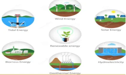
Figure 2.3: Types of Renewable Resources 2.2 Types of Renewable Energy Resources
• Solar Energy • Tidal Energy • Wind Energy
• Bio-mass Energy • Geothermal Energy
Every resource can not be deployed anywhere, physibilty of the resources is required to take into account, like wind energy cannot be installed where the flow rate of the air is less, each system has its demands.
We will be discussing only the solar energy system because we will only use this in our study.
2.2.1 Solar Energy System:
Solar Energy System also known as Photo-Voltaic system provide us electrical energy, it takes the sunlight as input and convert it into direct current DC electrical energy, the photovoltaic PV system is one of the fastest growing renewable resource in present age, because of its easy instalation, zero noise very low running cost and many other benefits.
Figure 2.4: Home based Solar Energy System
As we know the photo-voltaic system provides us DC electrical energy because of its inheretance property, if the load requires DC it can be directly used with the help of simple Buck-Boost converter in case of normal/light load, but if there is any torque load or heavy load needed to be supplied by the system then, a bunch of capacitors or a battery energy storage system is required to be installed in the system, And Secondly the inverter is also required if the load is operatedon AC power to operate.
1. Photo-Voltaic arrays 2. Inverter with controllers 3. Battery Storage or Capacitors 2.2.2 Photo-Voltaic Arrays or Solar Panels:
This is the first part of the system and the major part of the system, It is responsible to produce Electrical Power by using the sunlight as driving power. Photo-Voltaic arrays are constructed with a number of solar cells which are made bysemiconductor materialslikesilicon and some other impurities added in it to make conduction possible when photon energy fell on it. Solar units are mostly constructed withcrystalline silicon particles.
2.2.3 Solar cell
SC is made up of semiconductor and is the simplest unit of the photo-voltaic arrays. Different types of Semiconductor are used in the solar cell construction which are silicon, Cadmium telluridegallium arsenide. These semiconductor materials converts the sun-lightenergy into direct current DC electrical energy. When the photon energy of Sun-light strikes on the surfaceof solar cells,it produces positive and negative PN junctions because of the free electron in conduction band and the absence of electrons creates holes & If we attach the small DC load with positive & negative PN junction of this PV cell then current will flow through the load, the amount of current generated by one PV cell is very low however by using the PV cell strings and by connecting them in series parallel combination we can get the desired output power.
Photon energy is basically the energy obtained by sunlight. Phton energy is emitted in the form of packets these photon packets are known as quantums. The Sunlight’s wavelength is the key parameter for the energy contained by quantum.
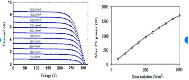
2.2.4 PV Cell Characteristic at different Irradiances
Figure 2.5:Characteristic of VI at different irradiation Source: Hamza Tédjini & Youcef Meslem, 2014
Figure 2.6:characteristics of Power of the PV cell with different irradiances value Source: Green,M.A,1981
Figure 2.7: characteristics ofPower of PV cell at different values of Temprature Source: Hamza Tédjini & Youcef Meslem, 2014
Figure 2.8: characteristics of VI of Solar cell with different temperature Source: V.Jafari Fesharaki, Majid Dehghani & J. Jafari Fesharaki 2011
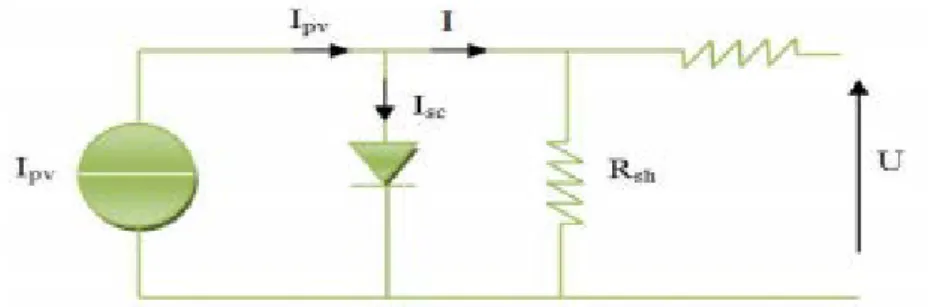
2.3 Mathematical Modeling of PV
Figure 2.9: Equivalent Circuit of PV Cell Source:Hamza Tédjini & Youcef Meslem, 2014
The mathematical equivalent circuit of the PV cell is shown in above figure, this is the simplest representation of any PV cell, as we can see from circuit starting from the left side Ipv is the current generated by the PV cell when photon energy strikes on it, later as we know PV cell is itself is PN junction so for its representation a parallel diode is attached to the system, R.shunt and R.series are the intrinsic resistance of the PV cell, for analysis purposes R.shunt is considered as infinite resistance and R.series zero ohm resistance, but only for calculation purposes, practically their values changes, Ipv is divided into two further currents first is I.short circuit, and I, I goes to load side ideally as there is zero current due to infinite resistance of R.shunt and V.open circuit remains maximum because there is no voltage drop due to ideally zero ohm resistance of R.series. all these assumptions are made to solve the mathematical representations in less complex way and formultaions can be made for further proceedings.
Now if we talk practically we can not rely on a single PV cell system, there are hundered of thousands PV cell are avaiable on a single array so that required amount of energy could be harnessed by PV arrays using the Sun’s photon energy, firstly series strings are made to reach the required voltage level, later on multiple series connected string are connected in parallel to eachother to achieve the required current value so the required Power could be achieved by using these clustered PV cells.
Figure 2.10: PV array with multiple strings Source:Trejos Grisales, L. A., Ramos Paja, 2016
The equation for characteristic of voltage and current for solar cell are given below.
Here,
𝐼𝑝ℎ is Photo-voltaic current generated by solar cell. 𝐼𝑠𝑐 is the short circuit current of PV cell
T is operational temperature in kelvins 𝐼𝑟 is Solar irradiance in (W/m^2)
The reverse saturation current 𝐼𝑟𝑠 equation is as under.
q is constant which is 1.602 × 10e(-19) coulumbs 𝑉𝑜𝑐 is the open circuit voltage
Ns is number of cells connected in series n is the identification to identify the diode
k is theBoltzmann’s constant whose value is = 1.380 x 10e(-23) (J/K) 𝐼0 is saturation current which differs according to the cell’s temperature.
Below equation describes the relationship between 𝐼0 saturation current and Temprature of the cell.
Tris 298.15 K => Nominal temperature in Kelvins
Eg0= 1.1 electron Volts =>(energy in band gap of semiconductor) So,
The PV module output is as under:
With
Now,
𝑁𝑃 shows number of Parallel connected PV modules 𝑅𝑠 shows the series resistance in ohms
𝑅𝑠ℎ is shunt resistance in ohms 𝑉𝑡 shows the diode thermal voltage.
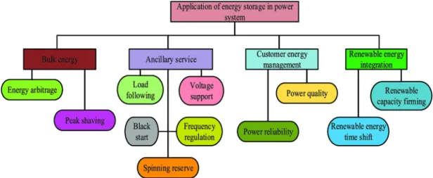
2.4 Energy Storage System (ESS):
A Micro-Grid consisting of renewable resources must be capable of harnessing the maximum renewable resources and no amount of energy go wasted, like if the Micro-Grid is autonomous and is not linked with utility grid, in such cases the grid needs the energy backup for the times when renewable resources like PV systems are unable to provides services in the night because of the absence light energy, for such cases the extra amount of energy in day times is stored using the energy storage systems, mostly batteries are used for storage purposes.
Figure 2.11: Application Purposes of Energy storage system. Source:Mohammad Faısal , Mahammad A. Hannan, 2018
A MG Micro-Grid is an local entity which is comprised of DER’s (distributed energy resources) to obtain local generated power reliability&utilization of sustainable energy in an efficient way. The Micro-Grid concept or the idea of linking renewable energy resourcs with ESS (energy storage systems) have gained popularity& interestof the emerging markets because of its capability of storinthe electrical energy inhours of off-peak & later supply electrical energy to loads at peak operating hours. But, existing energy storage systems (ESS) technologies faces multiple challenges in order to store the electrical energy because of various issues, for example, which are charging and discharging of batteries, reliability, life cycle, Safety, cost,size, life cycle, overall management. So, an advanced energy storage system ESS is needed to be designed with regard to Protection, capacity, energy management, control interface, energy, and characteristics to improve performance of energy storage subsystem ESS in Micro-Grid applications.
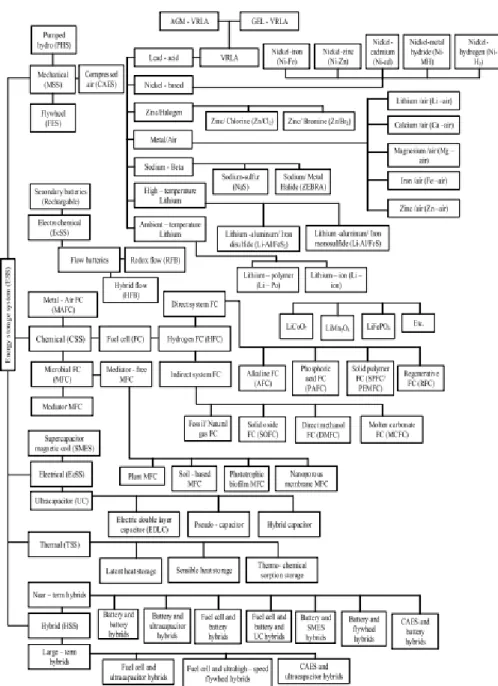
Figure 2.12: Detailed claasifications of energy storage technologies. Source:Mohammad Faısal , Mahammad A. Hannan, 2018
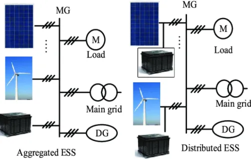
Below two types of ESS are shown, first one is aggregated system in which both the renewable resources (PV system and wind system) provide extra energy to a single but bigger energy storage systeem, while the other shown system is using indvidual energy storage system for each resource which is known as distributed energy storage system. Distributed energy storage system is more reliable than aggregated system but expensive to install.
Figure 2.13: Typical Configurations of Energy Storage System Source:Mohammad Faısal , Mahammad A. Hannan, 2018
2.5 Battery Controller
Battery controller is used to control the battery’s charging & discharging and other operations held at batteries, it makes it possible to maintain the battery State of charge minimum maximum discharging and maximum charging of the battery to ensure life cycle of the battery. Also it receive signal from the main controller either the system needs to get energy from the battery or the system is generating sufficient power which can charge the battery if ther battery state of charge is less than fully charged. Basically its it is consists of electronic switches like Mosfets and other switching circuits which are controlled by central controller.
2.6 State of charge (SOC):
The State of Charge SoC of a battery is numeric parameter which indictates the charging and discharging percentage of the battery, it varries from 0 Percentage to 100 percentage. The SoC can not be obtained directly from the battery, actually the voltage a the battery at any instance gives us information about the charging percentage of the battery. For example a battery which is fully charged and its 12 Volts DC battery and the no load voltage of the battery are 15 Volts
and when its fully discharged its voltages are 10 Volts, so keeping it in mind we have to callibrate the SoC in term of voltages, in battery controller system the monitoring of the battery SoC is being checked continuously by using a voltage sensor, so that the battery is not fully discharged nor over charged as both scenerios are not good for battery health. Practically the value of SoC is maintained between 20% to 95%.
2.7 Diesel Generator:
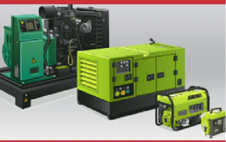
Diesel generator is an conventional resource of generation , In Islanded Micro-Grid configuration, Diesel Generator or any fuel running generation system is very much important to make the system reliable because there is no utility grid available which will feed the system in absense of primary generation system.
Figure 2.14:Diesel Generator
In this study, we have deployed SCIG squirrel cage induction generator.Diesel Generator is kept as secondary backup in our study, primary backup is energy storage system precisely which is battery bank system, Diesel Generator is needed to operate when there is no generation or less energy is generated by primary resources which is only Photo-Voltaic system in our case, lets suppose in the envening or in the night the PV is not enough to supply the critical loads and also the battery SoC is less than the minimum threshold, in this scenerio the Diesel Generator will start and take the responsibilty to supply the critical loads, the generation capacity of the DG is bit higher than the critical load because of two reasons, first one is that if in future there are extra loads are deployed in the system, the system shoud be capable to supply those future critical loads, and
the second reason is that to charge the batteries with the extra power which remains available after feeding the critical loads, the power rating selection of the Diesel Generator should not be too much greater because if the generator is producing extra power then definitely there is more fuel require to drive the combustion engine which will effect the generation cost which is key parameter for system running cost economic, also its not environment friendly because of the green house gases generation. Another idea is available for bigger system to improve the reliability and keep running cost low which is using more than one Diesel Generator but of low ratings which will operate in parallel mode according to the load demands. This will resuce to generation cost and make the system more reliable because if one generator is not working because of any fault, the second generator will operate and will meet the critical load requirements.
2.8 AC DCConverters:
AC DC converters are used for multiple purposes, it act as AC to DC converter and also DC to AC converter, in our study we have used 3 Phase AC DC Converter which can convert 3 phase AC electrical power to DC electrical power for charging the battery storage sytstem while the Diesel generator providing energy to the system, Also the other application is DC AC converterwhen the primary resource which is Photo-Voltaic in our case, is not able to feed the load and battery is usedto feed the loads. As we know that there are both AC and DC loads are available in the system, to feed the AC loads DC AC converter converts DC power into AC power.
Source: Azhar Ul Haq, Carlo Cecati, 2016
2.9 Buck-Boost Converters:
Buck-Boost or DC DC converters are used where we have to step up or step down DC voltage level, As we that transformers are not able to work on DC power, Buck-Boost converter are electronically designed transformer, by maintaing their duty cycle using main montroller, the can meet the output voltage requirements.
Figure 2.16: General circuit of Buck-Boost Converter Source: https://www.powerelectronics.com, Haifeng Fan, 2015
Here are two purposes of using the DC DC converter, the first one is to maintain the voltage coming from PV system to charge the battery storage system, the other perspective is to maintain the DC voltage for the DC loads connected to the system, in some studies or practical implementations MPPT algorithms and designed using Buck-Boost Converters.
Figure 2.17: Simulink circuit of Buck-Boost Converter with P&O MPPT Algorithm Source: Ahmed M Atallah, Almoataz Y. Abdelaziz, 2014
3. PROPOSED SYSTEM &METHODOLOGY:
Our proposed system is consist of PV system, battery storage system, inverter system, Diesel generator, Active harmonic filter, and control system. The system is primarily fed by PV system firstly it supply the loads and if there is extra power available in the system, the extra power is given to battery storage system so that in absence of solar power, battery storage must share the power to the system to supply the critical loads, battery storage system is primary backup and Diesel generator is deployed as secondary backup, in the absence of solar energy, and the battery is discharged Diesel generator operates to supply the loads.
Figure 3.2: Solar power, MPPT, Battery storage and Inverter system simulink circuit.
3.1 Photo-Voltaic System Operation:
The model of solar arrays which we have deployed in our simulink model is 11Soltech 1STH-25-WH, the array is consist of 25 parallel string each of 20 series string connected with each other. Overall output of the PV system is about 118kW, the voltage generated by PV system altogether are approximately 562 volts which are later fed to the MPPT system, the amount of current is approximately 210 Amps. The value of the temprature is set as 25. Different values of solar irradiances are set to the input of solar arrays so that the behaviour of power generation can be estimated in the presence of different values of real times irradiances.
A FWD free wheeling diode is placed at the output of PV system to protect PV system from the reverse currents by the other resources in the system.
Figure 3.3: PV System in Simulink
Figure 3.4: Power, Voltage and Current generated by solar arrays
Above pictures gives the stats of the generated power by solar modules, initially there is instability in the system which is in transients condition, later this become stable in steady state operation. After 2 unit index on the x-axis, there is a little reduction in power dues to the variability of the solar irradiance, and hence there is a little less power obtained by the system, we can see the stats on the gain table, the mean value of the power is about 8.5kw and the peak value is around 10kw in steady state operation.
3.2 Operation of Battery Storage System
The battery storage system which is used as the primary backup of the system. The battery storage system is consist of multiple connectecd lead acid batteries,
output voltages of the battery energy system are 600 VDC and the current rating of the battery storage system is 20 Ah, battery storage system can provide sufficient amount of power to the system which is 12kWh, which can support the critical loads in the system for an average duration while working alone in the absence of PV energy, and for longer duration when PV power is also supporting the system.
Two IGBT’s in battery storage system are used for switching purposes of the BSS because controller controls the operation and decides either to charge the BSS or to get energy from BSS in the absence of PV energy. These IGBT’s are are switched by the pulses provided by the central controller. Battery Voltage and SoC (state of charge)of the battery are being monitored by the controller. İnitial SoC is kept s 90 Percent, battey response time is set to 10 seconds, if BatterySoC(state of charge) is less than the allowed limit (which is between 10% to 25%), the controller will give the command to the Diesel Generator to start and feed the critical loads and if there is extra amount of energy available
after feeding the loads, this extra enegy will charge the battery storage system. otherwise Diesel Generator will operate in load following mode.
Figure 3.5: Battery Storage System in Simulink. 3.3 Operation of inverter System
The conventional H-bridge type three phase inverter consists of three legs, six pulses
delayed by the 120 degree to generate 3 phase AC power supply. Figure shows simulation circuit of H-bridge type three phase inverter. The switches are connected in threepairs S1 & S2 (red phase), S3 & S4 (yellow phase) and S5 & S6 (blue phase), each pair iscomplemented to each other. The circuit is a combination of three single phase invertersdriven by common DC voltage source. The voltage level at each phase of the inverter isequal to the voltage in 1 phase H-bridge inverter. The inverter can be operated in 120 mode or 180 mode. The inverter circuit works on the switching ON/OFF sequences of theelectronics devices. Theses electronic devices may BTJ/MOSFET/IGBTs etc, are used forthe switching purpose. At the output LCL filter is used, the SPWM signal and scope forSPWM signal is also shown.
SPWMThe inverter circuit works on the switching ON/OFF sequences of the electronics devices.
Figure 3.6: 3 Phase Inverter System in Simulink.
Theses electronic devices may BTJ/MOSFET/IGBTs etc, are used for the switching
purpose. SPWM is generated by comparing the carrier signal with reference or desiredsignal. The carrier signal is higher frequency (1-25 kHz) triangular waveform, and thereference signal is grid system sinusoidal voltage waveform. The block is called DC-DC PWM generator. Here the switching frequency is set up to5 kHz in DC-DC PWM generator block. If the synchronization of the inverter with gridsystem is not needed then three reference signals of sinusoidal waveforms delayed by 120each, are required. While comparing refence and carrier signals; as the magnitude of thereference signal increases the duty cycle (%) of the output signal increases and vice versa.The negative signals of the reference are complemented to convert into positive signals andthen given to DC-DC PWM generator. These SPWM signals are provided to the electronicdevices MOSET/IGBTs for switching. If the inverter is synchronized with other powersystem i.e. diesel generator, then we need to the reference signal of that source also. Herethree phases references signals are selected for spwm generation.
3.4 Operation of MPPT System:
Solar PV system has non-linear voltage, current and output power characteristics which
depends on solar irradiance (Watt/m2) and environmental temperature. The point of
maximum power changes as solar irradiance (Watt/m2) and environmental temperature
changes. For continuous operation it is necessary to use MPPT to deliver maximum powerto the load under different solar irradiance (Watt/m2) and environmental temperature.
Figure 3.7: MPPT Circuit in Simulink.
Similarly, the MPPT is also used for wind turbine to track the MPP under different wind
speed .In figure DC to DC boost convertor based MPPT circuit is shown, C1 is inputcapacitor and C2 is output capacitor, C1 receives charge from solar PV but it dischargesslowly, when the transistor is closed for short time the capacitor C1 discharges quickly andcurrent flows in inductor stores the energy (1/2 I2L). As the transistor switches off the storedenergy is delivered to capacitor C2. To avoid the discharging of the capacitor C2 throughinductor L and capacitor C1
reverse blocking diode is used. So, the charge of capacitor C2is delivered to the load. Thus, the quickly charging and discharging of capacitor C1,quickly receives energy from PV and delivers energy to the load. By doing this process themaximum power from solar PV is utilized by the external the load. The duty cycle (%) ofPWM is adjusted by the controller according to the MPPT algorithms when the power ofsolar PV changes.
There are some methods used for MPPT of solar PV system these are; i. MPP tacking by open circuit voltage (Voc)
ii. MPP tacking by short circuit current (Isc or Jsc) iii. Curve fitting method
iv. Differential method v. Hill climbing method a. Incremental conductance b. Perturb and Observe technique
Perturb and observe (P&O) algorithm is used for the MPPT circuit. In Perturb and Observe(P&O) method voltage is measured, the duty cycle can be increased or decreased accordingto P&O algorithm. The current is also measured to measure the power. The power of thelast and current perturbation is compared and then decide to increment the voltage ordecrement thevoltage by increasing and decreasing of the PWM. If there is increment inthe power then the voltage is increased otherwise the voltage is decreased. So, themaximum power tracking point is oscillating around the maximum power point (MPP). Toeliminate this issue the incremental conductance method is used for tracking of MPP
3.5 Operation of Active harmonic filter System:
This part of the system deals with power quality of the system, harmonics in the system due to non-linear loads affects the system power quality and it very important to deal with those harmonic components. There are three types of filter, active filter passive filter and hybrid filter, passive filter are rarely used these days because they are not dynamic. On the other hand, active filter is dynamic and can deal with a range of harmonics.
Active Filters is IGBT/MOSFET based converter which inject harmonics compensation parts in the line to cancels out the harmonics available in the line of the power system.
As per standards to IEEE 519; the total harmonic contents in power system should not be greater than 1.0% for the voltage range above 160 kV. For power system having hormonic contents more than 2.0 % are restricted
The AC output voltage of this h-bridge inverter is distorted and has large number of harmonic contents. This disturbed waveform of AC voltage is not only produced losses and heat, but it is also difficult to measure electrical quantities (voltage and current signals). The distorted voltage has multiple frequencies; each frequency has specific number and magnitude. The total distortion due to all frequencies components is known total harmonic distortion (THD). It is important to minimize the distortion in the output voltage, an LCL filter has been used at the output of the inverter. There are some common harmonic filters used to regulate/remove the harmonic contents in voltage and current.
i-Passive Filters are (Combination of any elements of R, L & C) a-Series Filter (Line Reactor)
b-Shunt Filter ii-Active Filters
iii-Hybrid Filter = Active + Passive Filter combination
Active Filters is IGBT/MOSFET based converter which inject harmonics compensation parts in the line to cancels out the harmonics available in the line of the power system.
As per standards to IEEE 519; the total harmonic contents in power system should not be greater than 1.0% for the voltage range above 160 kV. For power system having hormonic contents more than 2.0 % are restricted
Figure 3.8: Circuit of Active Harmonics System in Simulink.
3.6 Control unit:
Program
%%%%%%%%%%%%% Active Filter System %%%%%%%%
%%%%%%%%%%%%% JUNE-2020 %%%%%%%%%%%%%% function [P1, CB1, CB2, CB3] = fcn(Soc, G)
%#codegen
% % By Default the Following Output status will always remain same % % untill some conditions vary,
P1 =1; % % PWM BATTERY ON/OFF & Charging CB1 =1; % % Grid System Connect/Disconnect CB2 =0; % % Diesel Generator ON/OFF CB3 =0; % % Load on Battery
%%%%%%% The Output status of the control unit will be changed according to
%%%%%%% to the conditions defined below. if (G > 500)
P1=1; % Battery charge control, pwm (0.0-1.0) CB1 =0; % % Diesel Generator ON/OFF
CB2 =1; % % Solar Inverter ON/OFF CB3 =0; % % Load on Battery
end
%%%%%%%%%%%%%%%%%%%%%%%%%%%%%%%%%%%%%%% %%
if (G < 500 && Soc>=87.5)
P1=0; % Battery charge control, pwm (0.0-1.0) CB1 =0; % % Diesel Generator ON/OFF
CB2 =1; % % Solar Inverter ON/OFF CB3 =1; % % Load on Battery
end
%%%%%%%%%%%%%%%%%%%%%%%%%%%%%%%%%%%%%%% %%%%%%%%
if (G < 500 && Soc < 88.8)
P1=0; % Battery charge control, pwm (0.0-1.0) CB1 =1; % % Diesel Generator ON/OFF
CB2 =0; % % Solar Inverter ON/OFF CB3 =0; % % Load on Battery
end end
4. EXPERIMENTAL RESULTS:
Figure 4.1: PV voltage, Current and power outputs.
Figure 4.3: MPPT input & Output voltage.
Figure 4.4: Battery SOC Charging Discharging, load current and voltage, Load at 3.1 sec load shifted on diesel generator.
Figure 4.5: Rectifier load only Load side
Figure 4.6: Rectifier load only Source side Now Rectifier load +R Load
Figure 4.7: Rectifier load +R Load THD of load current
RL LOAD
Figure 4.9: Source Voltage, current and load current wave forms
Figure 4.11: RL Load current Harmonics Load Side
Figure 4.12: Rectifier and RL Load THDs, THD of source current RC load
Figure 4.13: Source Voltage, source current and load current wave forms @RC LOAD
Figure 4.16: THD of RLC Load at Load Side
Figure 4.17: THD of RLC Load at Source Side Type of Load THD I_Load % THD
I_Source %
Remarks
Rectifier 25.84 3.34 Within Permissible limits
of IEEE
Rectifier + R 19.06 2.54 Within Permissible limits
of IEEE
Rectifier + RL 17.71 1.86 Within Permissible limits
of IEEE
Rectifier + RC 32.25 3.17 Within Permissible limits
of IEEE
Rectifier + RLC 33.48 7.41 Within Permissible limits
5. CONCLUSİONS & FUTURE RECOMMENDATİONS:
An operational control strategy has been presented for a Battery- DG based microgrid in autonomous mode. The cost-effectiveness is achieved minimizing the use of DG, maximizing the fuel efficiency, utilizing the PV array power by MPPT operation, and dropping the dedicated converter for PV integration. The continuity and quality of power are maintained by use of a central controller and active filter control for eliminating the harmonics in current, while feeding nonlinear load. The proposed control has been tested experimentally with different loads, and performance has been compared with other control algorithms as well, to prove its superiority. The life of BES and DG has been enhanced by regulating the battery current within limits and making the DG current distortion free. Thus, the proposed multi-objective control strategy can be employed for any renewable energy-based system with an energy storage, having a fossil fuel-based generator for backup. The scheme can have vast use in rural, remote, or hilly areas, for powering telecommunication stations, hospitals etc, in future practices alot of work can be done in for mor economic purposes like deploying multiple diesel generators than using single generator which will reduce running cost, also more dynamic active harmonics filters can be designed which must be more fast by there converging speed according to the unkown harmonics generated in the system.
REFERENCES
[1]N. F. N. Ismail, I. Musirin, R. Baharom and D. Johari, "Fuzzy logic controller on DC/DC boost converter," 2010 IEEE International
Conference on Power and Energy, Kuala Lumpur, 2010, pp.
661-666.
doi: 10.1109/PECON.2010.5697663
[2]M. Castilla, J. Miret, J. Matas, L. G. de Vicuña, and J. M. Guerrero, “Control design guidelines for single-phase grid-connected photovoltaic inverters with damped resonant harmonic compensators,” IEEE Trans. Ind. Electron., vol. 56, no. 11, pp. 4492–4501, 2009, doi: 10.1109/TIE.2009.2017820.
[3]https://dergipark.org.tr/download/article-file/344935
[4]M. Castilla, J. Miret, J. Matas, L. García de Vicuña, and J. M. Guerrero, “Linear current control scheme with series resonant harmonic compensator for single-phase grid-connected photovoltaic inverters,”
IEEE Trans. Ind. Electron., vol. 55, no. 7, pp. 2724–2733, Jul. 2008,
doi: 10.1109/TIE.2008.920585.
[5]P. IEEE Standards Coordinating Committee 21 on Fuel Cells, Institute of Electrical and Electronics Engineers., IEEE-SA Standards Board., and IEEE Xplore (Online service), IEEE standard conformance test
procedures for equipment interconnecting distributed resources with electric power systems. Institute of Electrical and Electronics
Engineers, 2005.
[6]F. Katiraei and M. R. Iravani, “Power management strategies for a microgrid with multiple distributed generation units,” IEEE Trans.
Power Syst., vol. 21, no. 4, pp. 1821–1831, Nov. 2006, doi:
10.1109/TPWRS.2006.879260.
[7]J. Baek, J. Kim, J. Lee, H. Youn and G. Moon, "A Boost PFC Stage Utilized as Half-Bridge Converter for High-Efficiency DC–DC Stage in Power Supply Unit," in IEEE Transactions on Power Electronics, vol. 32, no. 10, pp. 7449-7457, Oct. 2017
[8]H. Patel and V. Agarwal, “Maximum power point tracking scheme for PV systems operating under partially shaded conditions,” IEEE Trans.
Ind. Electron., vol. 55, no. 4, pp. 1689–1698, Apr. 2008, doi:
10.1109/TIE.2008.917118.
[9]N. Femia, G. Petrone, G. Spagnuolo, and M. Vitelli, “Optimization of perturb and observe maximum power point tracking method,” IEEE
Trans. Power Electron., vol. 20, no. 4, pp. 963–973, Jul. 2005, doi:
10.1109/TPEL.2005.850975.
[10]L. Huber, Y. Jang and M. M. Jovanovic, "Performance Evaluation of Bridgeless PFC Boost Rectifiers," in IEEE Transactions on Power
Electronics, vol. 23, no. 3, pp. 1381-1390, May 2008.
[11]Y. H. Ji, D. Y. Jung, J. G. Kim, J. H. Kim, T. W. Lee, and C. Y. Won, “A real maximum power point tracking method for mismatching
compensation in PV array under partially shaded conditions,” IEEE
Trans. Power Electron., vol. 26, no. 4, pp. 1001–1009, 2011, doi:
10.1109/TPEL.2010.2089537.
[12]K. Ishaque and Z. Salam, “A deterministic particle swarm optimization maximum power point tracker for photovoltaic system under partial shading condition,” IEEE Trans. Ind. Electron., vol. 60, no. 8, pp. 3195–3206, 2013, doi: 10.1109/TIE.2012.2200223.
[13]C. Fei, F. C. Lee, Q. Li, "High-efficiency high-power-density LLC converter with an integrated planar matrix transformer for high-output current applications," IEEE Trans. Ind. Electron., vol. 64, no. 11, pp. 9072-9082, Nov. 2017.
RESUME
Name Surname: Danish Ali
Place/Date of Birth: Burewala ,Pakistan, 12-06-1993 E-mail: [email protected]
Education:
2013-2017, BSC Electrical Engineering GC University Faisalabad, Pakistan 2018-2020 MSC Electrical and Electronics Engineering. İstanbul Aydın University, Istanbul Turkey
Work Experience:
September 2019- July 2020 Product support Engineer at IMB Electric İstanbul,Turkey
Languages:
• Urdu: Native Language • English: Advanced • Turkish: Intermediate
Skills:
• Communication, Teamwork, Problem Solving