EXPERIMENTAL INVESTIGATION OF THE EFFECT OF INTERNAL STRUCTURE MODIFY ON PERFORMANCE IN TPTC TYPE HEAT PIPES
DRIVING SOLAR
A THESIS SUBMITTED TO
THE INSTITUTE OF GRADUATE PROGRAMS KARABUK UNIVERSITY
BY
ALSEDIQ S. S. FREJ
IN PARTIAL FULFILLMENT OF THE REQUIREMENTS FOR THE DEGREE OF MASTER OF SCIENCE IN
DEPARTMENT OF ENERGY SYSTEMS ENGINEERING
“I declare that all the information within this thesis has been gathered and presented in accordance with academic regulations and ethical principles and I have according to the requirements of these regulations and principles cited all those which do not originate in this work as well.”
ABSTRACT
M. Sc. Thesis
EXPERIMENTAL INVESTIGATION OF THE EFFECT OF INTERNAL STRUCTURE MODIFY ON PERFORMANCE IN TPCT TYPE HEAT PIPES
DRIVING SOLAR
Alsediq S. S. FREJ
Karabük University Institute of Graduate Programs Department of Energy Systems Engineering
Thesis Advisor:
Prof. Dr. Mehmet ÖZKAYMAK January 2020, 86 pages
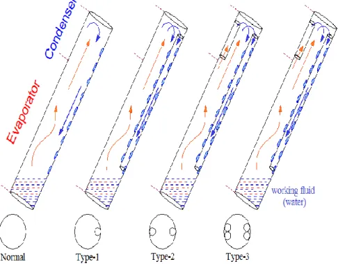
Heat pipes have be given great attention in solar energy applications, where they have great heat transfer potential. The purpose of this study is to experiment with the performance rate of a Tow-Phase Closed Thermosyphon (TPCT). The pipe is discharged from the air, while the water is used as a liquid to work at a rate of 1/3 of the size of the evaporator, and has been modified in the internal structure, by installing small pipes in different numbers inside the heat pipes in different cases, normal pipe, type I, type II and type III, then heat pipes are placed at different angles to receive solar radiation. It turns out that the value of solar radiation increases when the angle of inclination of the pipes is small, adjustment in the internal structure change
the performance also, where the best performance was at the angle of inclination 26° of the modified heat pipe by adding two small tubes inside.
Key Words : Solar Energy, Performance, modify, inner structure, (TPCT) heat pipe.
ÖZET
Yüksek Lisans Tezi
TPCT TİPİ ISI BORULARININ GÜNEŞ SÜRÜŞÜNÜN PERFORMANS ÜZERİNE PERFORMANS ÜZERİNE İÇ YAPI MODİFYASYON ETKİSİNİN
DENEYSEL İNCELENMESİ
Alsediq S. S. FREJ
Karabük Üniversitesi Lisansüstü Eğitim Enstitüsü
Enerji Sistemleri Mühendisliği Anabilim Dalı Tez Danışmanı:
Prof. Dr. Mehmet ÖZKAYMAK Ocak 2020, 86 sayfa
Isı boruları, yüksek ısı transfer potansiyeline sahip oldukları güneş enerjisi uygulamalarına büyük önem verilmiştir. Bu çalışmanın amacı, bir İki Fazlı Kapalı Termosifon (TPCT) performans oranı ile deney yapmaktır. Boru havadan boşaltılır, su ise buharlaştırıcının boyutunun 1 / 3'ü oranında çalışmak için bir sıvı olarak kullanılır ve iç yapı içinde küçük borulardaki farklı sayılardaki küçük borular monte edilerek modifiye edilir. farklı durumlarda ısı boruları, normal boru, tip I, tip II ve tip III, daha sonra ısı boruları güneş ışığını almak için farklı açılara yerleştirilir. Boruların eğim açısı küçük olduğunda güneş radyasyonu değerinin arttığı, iç yapıdaki ayarların değiştiği ortaya çıktı.
Aynı zamanda, en iyi performansın, içine iki küçük tüp eklenerek, değiştirilmiş ısı borusunun 26 ° eğim açısında olduğu performans.
Anahtar Kelimeler : Güneş Enerjisi, Performans, değişiklik, iç yapı, (TPCT) ısı borusu.
ACKNOWLEDGMENT
I would like to express my deepest appreciation to Prof. Dr. Mehmet ÖZKAYMAK. Who gave me the excellent opportunity to do this wonderful project, thank you for give assistance to be a support and a basis for my knowledge to start my research mission.
Furthermore, I would also like to acknowledge with much appreciation the crucial role of the Dr. Engin ÖZBAŞ. Who gave the permission to use all required equipment and the necessary materials to complete the task, and participation in this research project.
I dedicate this work to my mother and thank my entire family and friends who supported me during my academic career.
CONTENTS Page APPROVAL ... ii ABSTRACT ... iv ÖZET ... v ACKNOWLEDGMENT ... vii CONTENTS ... viii LIST OF FIGURES ... xi
LIST OF TABLES ... xii
SYMBOLS AND ABBREVITIONS INDEX ... xiii
PART 1 ... 1 INTRODUCTION ... 1 1.1. TYPES OF ENERGY ... 1 1.2. ENERGY RESOURCES ... 2 1.2.1. Exhaustible resources ... 2 1.2.1.1. Natural Coal ... 2 1.2.1.2. Natural Gas ... 2 1.2.1.3. Petroleum ... 2 1.2.2. Renewable resources ... 3 1.3. RENEWABLE ENERGY ... 3
1.3.1. Type of Renewable Energy ... 4
1.3.1.1. Wind Energy ... 4
1.3.1.2. Solar Energy ... 4
1.3.1.3. Hydrogen Energy ... 5
1.3.1.4. Hydroelectric Energy ... 5
1.3.1.5. Ocean and Sea Energy ... 5
1.3.1.6. Geothermal Energy ... 6
Page
1.4. SOLAR ENERGY ... 7
1.4.1. The Success of Solar Systems ... 9
1.4.2. Solar Collectors ... 10
1.4.2.1. Flat Plate Solar Collector ... 10
1.4.2.2. Parabolic Trough Collector ... 11
1.4.2.3. Evacuated Tube Solar Collectors ... 12
1.5. HEAT PIPE ... 13
PART 2 ... 16
HEAT PIPE ... 16
2.1. TYPES OF HEAT PIPES ... 18
2.1.1. Micro Heat Pipes ... 18
2.1.2. Loop Heat Pipes ... 19
2.1.3. Grooved Heat Pipes ... 20
2.2. WICK OR CAPILLARY STRUCTURE ... 21
2.2.1. Sintered Wick ... 21
2.2.2. Groove Wick ... 22
2.2.3. Screen Mesh Wick ... 23
2.3. (TPCT) TYPE OF HEAT PIPE ... 24
PART 3 ... 29
MATERIAL AND METHODOLOGY ... 29
3.1. MANUFACTURING AND PREPARATION MODULATION ... 30
3.2. EXPERIMENT DESCRIPTION ... 33
PART 4 ... 36
RESULTS AND DISCUSSION ... 36
PART 5 ... 50
CONCLUSION ... 50
Page
REFERENCES ... 52
APPENDIX ... 62
Appendix A. Results of Normal Heat Pipe whit angle 26° ... 62
Appendix B. Results of Heat Pipe Type-1 whit angle 26° ... 64
Appendix C. Results of Heat Pipe Type-2 whit angle 26° ... 66
Appendix D. Results of HEAT PIPE Type-3 whit angle 26° ... 68
Appendix E. Results of Normal Heat Pipe whit angle 41° ... 70
Appendix F. Results of Heat Pipe Type-1 whit angle 41° ... 72
Appendix G. Results of Heat Pipe Type-2 whit angle 41° ... 74
Appendix H. Results of Heat Pipe Type-3 whit angle 41° ... 77
Appendix I. Results of Normal Heat Pipe whit angle 56° ... 79
Appendix J. Results of Heat Pipe Type-1 whit angle 56° ... 81
Appendix K. Results of Heat Pipe Type-2 whit angle 56° ... 83
Appendix L. Results of Heat Pipe Type-3 whit angle 56°... 85
LIST OF FIGURES
Page
Figure 1. 1. Energy consumption and carbon dioxide emission. ... 7
Figure 1. 2. Solar generation in recent years ... 8
Figure 1. 3. Annual growth rate of renewable technologies between 1990 and 2016 . 9 Figure 1. 4. Flat Plate Collector ... 10
Figure 1. 5. Flat Plate Collector with Glass Covers ... 11
Figure 1. 6. Parabolic trough collector ... 11
Figure 1. 7. Evacuated Tube Solar Collector ... 12
Figure 2. 1. Schematic of the working principle, with direction of the vapor and liquid flows ... 18
Figure 2. 2. Common micro heat pipe cross-sections ... 19
Figure 2. 3. Schematic of Principle of Operation of a Loop Heat Pipe ... 20
Figure 2. 4. Schematic the forms of grooves present in the Grooved Heat Pipes ... 21
Figure 2. 5. Sintered wick ... 22
Figure 2. 6. Groove wick ... 22
Figure 2. 7. Mesh wick ... 23
Figure 2. 8. Schematic of heat pipe (TPCT) ... 25
Figure 2. 9. Schematic of heat pipe (TPCT) system ... 26
Figure 3. 1. DeltaOhm LP PYRA 02 pyranometer, ORDEL UDL100. ... 29
Figure 3. 2. Schematic of the heat pipe length and diameter. ... 30
Figure 3. 3. Photograph showing the tubes used in the experiment... 31
Figure 3. 4. Schematic of the types of tests used in the heat pipe... 31
Figure 3. 5. Photograph showing internal modifications made on the heat pipe. ... 32
Figure 3. 6. Schematic of the points installed thermocouples. ... 33
Figure 3. 7. Photograph showing the heat pipes receives solar radiation at an angle of 26°. ... 33
Page Figure 3. 8. Photograph showing the heat pipes receives solar radiation at an angle of 41°. ... 34 Figure 4. 1. Temporal radiation intensity with different angles... 36 Figure 4. 2. Temperature of the water tank with various heat pipes at an angle of 26°. ... 37 Figure 4. 3. Temperature of the water tank with various heat pipes at an angle of 41°. ... 37 Figure 4. 4. Temperature of the water tank with various heat pipes at an angle of 56°. ... 38 Figure 4. 5. Temperature of the water tank of the normal type heat pipe at angles 26°, 41°, 56°. ... 39 Figure 4. 6. Temperature of the water tank of the type 1 heat pipe at angles 26°, 41°, 56°. ... 39 Figure 4. 7. Temperature of the water tank of the type 2 heat pipe at angles 26°, 41°, 56°. ... 40 Figure 4. 8. Temperature of the water tank of the type 3 heat pipe at angles 26°, 41°, 56°. ... 41 Figure 4. 9. Temperatures at the thermocouple points on the along heat pipe of the normal type at an angle of 26°. ... 42 Figure 4. 10. Temperatures at the thermocouple points on the along heat pipe of the type 1 at an angle of 26°. ... 42 Figure 4. 11. Temperatures at the thermocouple points on the along heat pipe of the type 2 at an angle of 26°. ... 43 Figure 4. 12. Temperatures at the thermocouple points on the along heat pipe of the
type 3 at an angle of 26°. ... 43 Figure 4. 13. Temperatures at the thermocouple points on the along heat pipe of the
normal type at an angle of 41°. ... 44 Figure 4. 14. Temperatures at the thermocouple points on the along heat pipe of the
type 1 at an angle of 41°. ... 45 Figure 4. 15. Temperatures at the thermocouple points on the along heat pipe of the
type 2 at an angle of 41°. ... 45 Figure 4. 16. Temperatures at the thermocouple points on the along heat pipe of the type 3 at an angle of 41°. ... 46 Figure 4. 17. Temperatures at the thermocouple points on the along heat pipe of the
normal type at an angle of 56°. ... 46 Figure 4. 18. Temperatures at the thermocouple points on the along heat pipe of the
type 1 at an angle of 56°. ... 47 Figure 4. 19. Temperatures at the thermocouple points on the along heat pipe of the
type 2 at an angle of 56°. ... 48 Figure 4. 20. Temperatures at the thermocouple points on the along heat pipe of the
LIST OF TABLES
Page
Table Appendix A. Results of normal heat pipe whit angle 26° ... 62
Table Appendix B. Results of heat pipe Type-1 whit angle 26° ... 64
Table Appendix C. Results of heat pipe Type-2 whit angle 26° ... 66
Table Appendix D. Results of heat pipe Type-3 whit angle 26° ... 68
Table Appendix E. Results of normal heat pipe whit angle 41° ... 70
Table Appendix F. Results of heat pipe Type-1 whit angle 41° ... 72
Table Appendix G. Results of heat pipe Type-2 whit angle 41° ... 74
Table Appendix H. Results of heat pipe Type-3 whit angle 41° ... 77
Table Appendix I. Results of normal heat pipe whit angle 56° ... 79
Table Appendix J. Results of heat pipe Type-1 whit angle 56° ... 81
Table Appendix K. Results of heat pipe Type-2 whit angle 56° ... 83
SYMBOLS AND ABBREVITIONS INDEX
ABBREVIATIONS
CNC : Computer Numerical Control CO2 : Carbon Dioxide
EDM : Electric Discharge Machining FGHP : Flat Grooved Heat Pipe FPHP : Flat Plate Heat Pipe GHG : Greenhouse Gas H2O : Water
HVAC : Heating, Ventilation, and Air Conditioning IEA : International Energy Agency
IPCC : Intergovernmental Panel on Climate Change LCOE : Levelized Cost Of Energy
LHP : Loop Heat Pipes
R&D : Research and Development
TPCT : Two-Phase Closed Thermosyphons VOF : Volume of Fluid
PART 1
INTRODUCTION
Energy is the ability of the material to give forces capable of accomplishing a certain work, and it is the ability possessed by a system to produce the external activity or activity, which is the abstract entity, which is known only through its transformations [1]. Nevertheless, it is significant to remember that just because the energy is available, it does not mean it is necessarily exist to perform the work [2]. Energy can be changed from one form to another but energy cannot be created nor destroyed. This concept is known as energy conversion or the first thermodynamics law. For example, electrical energy or usable energy are produced by several types of devices such as batteries, fuel-burning heat engines, fuel cells, generators and magneto hydrodynamic systems. While the nuclear energy is potential energy because it is produced from the configuration of subatomic atoms in the nucleus of the atom [3]. There may be overlap between energy forms and the object always retains more than one type of energy at a time.
1.1. TYPES OF ENERGY
Types of energy can be listed as follow [4]:
Mechanical Energy Kinetic Energy Thermal Energy Nuclear Energy Chemical Energy Electromagnetic Energy Gravitational Energy Potential Energy
1.2. ENERGY RESOURCES
To get kinds of energy, we must identify their sources:
1.2.1. Exhaustible resources
1.2.1.1. Natural Coal
Coal is a black or brown flammable and combustible rock, when the combustion it gives energy in the form of heat, this energy is used for heating or as fuel for old trains in the era of the steam machine. But nowadays coal is used to produce electricity, which is currently the primary use of this type. Coal is composed of carbon in addition to varying proportions of other elements such as sulfur, nitrogen and oxygen.
It is extracted from the earth's layers, and vertical or surface mines or open mines are made to extract this coal.
1.2.1.2. Natural Gas
Natural gas, when extracted from the ground, is in the form of a mixture of gases that can be ignited, and are naturally present inside the earth at specific depths, when increasing the pressure and heat on the decomposing materials the greater the concentrations of natural gas and better quality. The gas is converted into a liquid for easy transfer from one place to another by cooling it to a temperature below 127 ° C and using it in many implementations.
1.2.1.3. Petroleum
Crude oil, also called black gold, is a dense, flammable liquid. Located in the upper earth crust layer. It is a very complex mixture of hydrocarbons. As for the composition, shape and purity, it all depends on where it is extracted. One of the most significant sources of primary energy. The first world destination for the
production of electric power by burning and exploiting it. Very reliable in the operation of factories - all means of transport. It is also a basic raw material for many chemical products such as fertilizers, plastics, fabrics, artificial leather, and many other modern products.
1.2.2. Renewable resources
Renewable energy is found in many forms as follow:
Wind Energy Solar Energy Hydrogen Energy Ocean & Sea Energy
Given the insane demand for energy, the world sees renewable energy as the only salvation, as it is environmentally friendly and its resources are inexhaustible [3,5]. The universal scientific consensus confirms that fossil fuel combustion accounts for the majority of anthropogenic global greenhouse gas (GHG) emissions, contributing meaningfully to the global climate change (IPCC, 2012). Therefore, countries around the world work on setting ambitious goals in order to decrease the carbon emission and increase the renewable energy share to reduce the terrible consensus of global warming [5].
1.3. RENEWABLE ENERGY
By the time, the global demand on energy is increasing and the traditional energy sources such as petroleum and coal are exhausting. In near future, the renewable resources of energy will play an important role. The renewable energy is also called as ―the alternative energy‖ can be defined as the energy that generated from natural source which is not depleted when used such as solar and wind energy. Since the renewable energy does not harm the environment, it gained high popularity. It is expected that the use of fossil fuel will be surpassed at the time where the renewable energy is booming around the world. It is seen that the wide use of fossil fuel such as
coal is one of the reason for climate change [4]. In spite of the oil crisis happened in previous years and damage caused by the use of fossil fuel, the renewable energy sources have not reach into high level to compete with fossil fuel. Nevertheless, the world tends to reduce the carbon dioxide and other emissions through emission regulations, taxes of carbon and subsidies of biomass and thus, the renewable energy would be a cost competitive [6].
1.3.1. Type of Renewable Energy
1.3.1.1. Wind Energy
Wind power can be defined as the power resulted from the use of airflow and atmosphere movement is driven by temperature differences at the earth surface because of changing temperature of earth surface when ignited by sunlight. This type of renewable energy is common and it is used for many purposes such as pump water and generate electricity by wind turbines to mechanically power generators for electricity. However, it needs extensive areal coverage in order to generate high amounts of energy. Wind energy is considered a good alternative to fossil fuels where it is plentiful, renewable, and clean, uses little lands, extensively spread and produces no greenhouse gas emissions through the operation [5].
1.3.1.2. Solar Energy
The sun is the final source for all energy sources and fuel we use, and it produced the energy for billions of years. People used the solar radiation for thousands of years for many purposes such as for warmth and dry fruit, grains and meat. By time, many techniques developed in order to collect the solar energy for heating and convert it to electricity [6].
1.3.1.3. Hydrogen Energy
Hydrogen is the most abundant element in our world and simplest one where it comprises of one proton and one electron. This element does not occur in naturally but it is existed in organic compounds (hydrocarbons including methanol, gasoline, propane and natural gas) and water (H2O). Moreover, hydrogen is produced under specific circumstances by some bacteria and algae using sunlight as a source of energy. This element is rich in energy and produces little or no pollution when it is burned. The fuel cells of hydrogen convert the probable chemical energy of hydrogen to electricity with the existing of pure water and heat as only byproducts. Nevertheless, the widespread and practical marketing for fuel cells of this element is still limited until decreasing costs and enhance the durability [7].
1.3.1.4. Hydroelectric Energy
Hydropower is not considered a new discovery but is the oldest, greatest, and most trustworthy energy source that used in the world. Currently, many ways are used to capture the kinetic energy of flowing rivers and transform to hydroelectricity. One of the most popular type of energy is created by system where dam is built to store the water in reservoir and when it is released, the water flows through turbines to generate electricity. This system is the most common form of the renewable energy. The features of this project is that it does not produce any direct wastes [8].
1.3.1.5. Ocean and Sea Energy
The energy generated from the waves and the phenomenon of tides.
Wave Power: Wave power is the transport of energy by waves of ocean surface and this energy is captured to be exploited in useful work. For instance, it is used for desalination of water and generation of electricity. Systems of wave power comprise the use of floating buoyed device and
create the energy by motion of snake or the mechanical movement from the wave's peaks and troughs [9].
Tidal Power: Tidal power is considered a probable source of renewable energy similar to the wind power because tides are stable and expectable. The tides are used for a long time since the days of ancient Rome. The incoming waters are stored in large ponds and when the rides went out, they twisted the waterwheels which created mechanical power to mill grain [10].
1.3.1.6. Geothermal Energy
As the name refers, this type of energy uses the heat of the earth itself. The geothermal energy is captured from the hot rock, shallow ground or hot water and the use of hot water and steam from the earth in order to run the power stations. As well as, this type of energy uses heat pumps to cool buildings in the summer season or heat the buildings in winter seasons. It cannot be used to produce electricity but it may be used to reduce the need of other power to preserve comfort heat in the buildings [11].
1.3.1.7. Biomass Energy
The biomass energy is another type of renewable energy and it is derived from the biomass to generate the liquid fuels that can be used in transportation such as biodiesel and ethanol. Also, it can be used to generate heat and electricity by the use of animal wastes and plant matter. When it is appropriately converted, the biomass energy is low-carbon energy source with little amount of pollution. However, this type of renewable energy remains expensive because it has not developed quickly as the wind and solar energy. It may effect negatively on the environment if it is not managed appropriately [12].
1.4. SOLAR ENERGY
When we say solar energy, it includes both solar thermal, which uses the heat of the sun light and solar cells or photovoltaic cells, which convert the sun light into electricity. Increased investment and efforts were poured into solar energy research in recent several years, but the outcome is slow [13].
Then, why do we study about solar energy? Why are companies and scientists eager to do research around solar energy despite the current small contribution to the total energy? The answer is in solar energy’s potential capacity.
Solar energy that we receive on earth in a year is about 12000 times larger than the total energy consumption of the whole world in a year. In comparison, the wind has the capacity of approximately 7 times larger [14].Many people in this field anticipate that solar energy will be a dominant renewable energy source in next few decades.
If we want to know the answer to the previous questions on the importance of the use of solar energy, let us consider the primary energy consumption and emission of carbon dioxide have high increase in latest years as shown in Figure 1.1.
Figure 1.1. Energy consumption and carbon dioxide emission [15 .
It has increased from 3701.5 Mt in 1965 to more than 13511 Mt in 2017. Moreover, emissions of carbon dioxide gas increased from 11189.5 Mt in 1965 to 33444 Mt in 2017 [15]. The necessity of developing the renewable energies is clear from high
increase in greenhouse gas emission and energy consumption. Recently, the renewable energies share in electricity and other applications have significantly increased [16, 17]. Many applications use the solar energy including cooling [18], heating [19,20], electricity generation [21,22] and desalination [23,24]. PV panels and thermal power plants are used in electricity generation. In terms of electricity generation, PV modules convert the sunlight directly to electricity [25].
It is possible to use the thermal energy of sun in order to run the power plant itself or to help in fossil fuels. In solar assisted power plants, the absorbed thermal energy of the sun is used to preheat the working fluid of the power cycle that result in efficacy enhancement and decrease the emission of greenhouse [26]. In recent years, the generation of solar energy has increased because of its flexible applications and availability in many regions of the world as shown in Figure 1.2 [15].
BLUE Map scenario of International Energy Agency (IEA) mentioned that the solar energy share in the generation of global electricity should reach into 11% by 2050 [27]. Recently, because of the development in R&D projects and technologies, Levelized Cost of Energy (LCOE) generated by solar sources has descending trend. The decrease of LCOE refers to more reasonable energy cost for consumers. Many factors determine the cost of electricity generated by the solar energy such as the applied technology and climate conditions [28, 29, 30].
Figure 1.2. Solar generation in recent years [15].
As we mentioned earlier, the use of solar energy will grow significantly because of adopted policies to develop the renewable energy. Solar PV with growth rate of
37.3% achieves the highest growth rate in renewable energies between 1990-2016. Figure 1.3 shows the growth rate of other renewable technologies.
Figure 1.3. Annual growth rate of renewable technologies between 1990 and 2016 [32].
1.4.1. The Success of Solar Systems
There are many reasons behind the success of solar systems as follow:
Technologies with simple costs thanks to increased competence and effectiveness.
Cost of systems is low.
Increase the awareness of solar systems in decreasing the emission of Carbone Dioxide [33, 34] and offering energy access [35].
More promising political circumstances motivated by governmental incentives and regulations [36, 37].
Consequently, solar energy implementation became important in order to make cities, neighbourhoods and buildings move quickly towards this clean energy [38].
1.4.2. Solar Collectors
Solar collectors perform an important function that is the conversion of solar radiation inti useful heat. They are existed in two types, concentrated and non-concentrated solar collectors. In general, non-concentrated solar collector are direct absorption solar collectors and parabolic solar collectors whereas flat plate is a non-concentrated solar collector.
Flat plate solar collector. Parabolic trough collector. Evacuated tube solar collector.
1.4.2.1. Flat Plate Solar Collector
This type of collector is used in most of the solar energy existed in the world.
Figure 1.4. Flat plate collector [8].
Flat Plate Solar Collector are relatively easy to preserve and cheap if compared with other types of collar collectors. Figure 1.4 shows a typical flat plate solar collector and involves a flat box comprising a black coated copper plate entrenched with tubes located in serpentine fashion or in parallel tubes as shown in Figure 1.5. In addition, the plate is lined with the lining at the plate bottom and with one or two glass or plastic covers on the top [8 , 9].
Figure 1.5. Flat plate collector with glass covers [9].
1.4.2.2. Parabolic Trough Collector
This type of collectors is a simple parabolic dish that focus the energy of the sun on a thermal receiver mounted at the focal point of the dish. The temperature obtained by this collector is reached to 1000°C. A simple parabolic trough collector is shown in Figure 1.6.
Figure 1.6. Parabolic trough collector [41].
The output from one dish is 25 kW only because of its limited size. Another type of parabolic trough collector is the central receiver or solar tower. This type consists of thousands of mirrors and cane track the sun. These mirrors are organized round a
central tall tower. The heat transfer fluid of this type of collectors are molten salt, air, water or steam and liquid sodium. It flows through the receiver and collect the heat. The temperature convoluted are in the region of 300-1000°C. It is normally used to create steam to generate electricity [41].
1.4.2.3. Evacuated Tube Solar Collectors
Evacuated tube solar collector contains a black coated copper tube comprising a heat pipe fluid surrounded in an evacuated glass tube. Normally, either 20 or 30 tubes are inserted in row and the top of the copper tubes is linked to a heat exchanger located in the top header of the collector as shown in the Figure 1.7. The fluid of collector is passed through its head and it is heated when the tube exposes to solar energy.
Figure 1.7. Evacuated tube solar collector [42].
The main feature of the evacuated tube collectors is the loss of heat because of the convection from the surface of the hot absorber to the surrounding is removed because of the vacuum conditions and the unique loss if because of the radiation that is not important. This type of collectors can achieve higher collector fluid temperatures if compared with flat plate unit. It is possible to achieve high efficiency with this type of collectors even at a very low surroundings temperature [42].
1.5. HEAT PIPE
70% of the energy in the world is consumed as heat. It is important to shrink the carbon footprint by reducing the energy use and the irreversibility’s due to heating and friction, because the energy costs are going up continuously. This reduction can be obtained by using heat exchangers or by heat pipes [43, 44]. Heat pipe is considered a heat transfer device which allow a high heat transfer between the evaporator and condenser during the liquid-vapor stage change of the fluid [45]. A heat pipe can transfer the heat from one end to the other many times faster than a metal bar with the same material and size [46]. Heat pipes are used in electronic devices, in hospitals, hotels etc. in heating and ventilation (HVAC) systems, in space and nuclear technologies as a completely natural cooling apparatus and in some other industrial sectors [45].
Heat pipes have advantages of high thermal conductivity and a high heat flux. A high temperature difference between the heat source and the heated place is not needed for an effective heat transfer with heat pipes [47]. Transfer of the working fluid from the evaporator to the condenser is driven by the vapor pressure and becomes in vapor phase. Fluid condensed by stage change in the condenser is transferred to the evaporator by an installed wick or by the gravity [48]. Heat pipes are the best solutions that can be chosen for the thermal control by their affordable costs and excellent heat transfer abilities.
From the previous experiments on heat pipes, it is discovered that the efficiency and heat of the heat pipe is affected by the time of solar radiation first, the more increase of solar radiation the more heat is used. Also the variables that affect the efficiency of the evaporator diameter, the greater the diameter, the higher the temperature obtained in the water tank [49].
It has been observed from previous studies that the temperature of the water entering, the flow rate of the mass of the water entering, the permeability of the pipes and the absorption surface absorption have an explicit impact on the energy efficiency and exergy efficiency of the heat pipe evacuated tube solar collector. The increase in the
water temperature entering the evacuated from the solar collectors reduces the rate of heat transfer between the heat pipe's condenser and water [50].
Also influencing the solar system used for heat pipes is the type of fluid inside the thermal tube Studies have shown that efficiency varies depending on the type of fluid.
The literature reported many studies about heat pipe solar collectors. Riffat, et al [51] developed a theoretical model for investigating the thermal performance of a thin membrane heat-pipe solar collector. At their study, they designed and constructed thin membrane heat pipe solar collector from the solar radiation to be collected at nearly high efficiency and keep low cost of capital. Azad [52] studied theoretically and practically the heat pipe solar collector and the optimal rate of heated length-cooled length of the heat pipe. Hull [53] studied factors of heat transfer and thermal efficiency for heat pipe absorber array linked to a corporate manifold. He discovered that the array with less than ten pipes of heat have considerably less efficiency than the traditional collector of flow-through. Hussein [54] studied the different design factors of the natural circulation two phase closed thermosiphon flat plate solar water heaters by the user of the verified expanded model. Chun, et al [55] provided experimental setup where they tested five individual modules for only one heat pipe coupled with a thermal reservoir. They compared several working fluids (acetone, methanol, ethanol and water), different absorber surface treatment, heat pipes with or without wick and different thermal tank volumes. The results that obtained at that work with a compact solar heating system, which is designed to offer heating by solar water to low income families. Radhwan, et al [56] performed an experimental study in thermal performance of two R11 charged integrated solar water heaters by the use of forced and natural circulation water flows. The results of the study presented that inclination of the condenser integrated inside the collector frame had great impact on the natural circulation of the water flow system. Whereas it had no particular impact on the forced circulation flow system. Soin, et al [57, 58] investigated the thermal performance for the thermosiphon collector including boiling acetone and petroleum ether, and showed the impact of insolation and the liquid level on the performance of collector. Fanney, et al [59] performed experiment
in order to determine the effect of irradiance level on the thermal performance of the refrigerant charged home solar hot water system. The experiment concluded that the irradiance level was insignificant for the considered levels. Akyurt [60] has designed and manufactured many heat pipes. Each manufactured heat pipe has been combined to a prototype solar water heater. They used extensive testing program continued for more than one year and it revealed that the heat pipe works properly as an element to transfer heat in solar water heaters. Rittidech, et al [61] studied the interconnected heat pipe solar collector. They described a type of interconnected heat pipe solar collector that does not depend on the natural power of gravity and capillary. As well as, it does not need external power source.
PART 2
HEAT PIPE
Heat pipe is a high-efficiency heat exchange component that performs heat transfer by repeated stage change (evaporation, condensation) of a working fluid enclosed in a pipe. It can transmit a large amount of heat through its small cross-sectional area for long-distance transmission without external power [62]. It is a heat-transfer device combines between the concepts of both phase transition and thermal conductivity to effectively manage heat transfer between two solid interfaces. In general, they referred as the "superconductors" of heat because they have high heat transfer ability and ratio with nearly no loss of heat.
The liquid in contact with thermally conductive solid interface in the hot surface of the heat interface turns to vapor by absorbing the heat from that surface. Later, the vapor travels across the pipe of heat to the cold surface, condenses back to a liquid, and leads to release the latent heat. Then, the liquid returns back to the hot interface by either the capillary action, gravity or centrifugal force and the cycle will be repeated. The direction of vapor and liquid flows are shown in Figure 2.1. The pipes of heat are high efficient thermal conductors because of the very high heat transfer factors of boiling and condensation. The efficiency of thermal conductivity differs with length of the heat pipe, and can attitude 100 kW/(m⋅K) through the long heat pipes, in comparison with about 0.4 kW/(m⋅K) for copper. In addition, another advantage characterizes the heat pipes to be much lighter than the rods of copper [68].
In the field of chemical industry, there are many needs for efficient and energy-saving heat exchange components. The heat pipis characterize by many advantage and thus, they are used in various fields including furnace waste heat recovered, steam generator, air preheater, and chemical reactors [62].
The receiver of heat pipis is an important element in advanced solar energy systems of space stations. It integrates heat transfer, heat absorption and thermal storage as an entire [63]. Through periods of sunlight in the orbit, the hear receiver absorbs the solar energy that reflected from the sunlight reflector over the incidence window, some energy transfer circulating working gas unswervingly, the remaining store in phase change thermal storage supplies. Through the eclipse periods in the orbit, the materials of thermal storage release heat to circulating working gas, and thus, the entire system may work effectively during the eclipse periods [63].
The heat pipe was discovered in 1942 by Gaugler, who registered its first patent in 1944 to be used in a refrigeration system. ln 1963, Grover registered a patent of a device with the name of heat pipe presenting a short theoretical introduction and some experimental results obtained using a heat pipe with metallic mesh as a wick and sodium as a working fluid. The first publication of a heat pipe was done by Grover et alli [64, 65]. After wards, the number of publications rapidly increased. Cotter 1965 [64, 66] published the first article that contained a comprehensive theoretic unidimensional global design was published by Cotter 1965 [64, 66]. Bienert and Wolf insrtd introduced the use of heat pipes in solar collectors. They inserted a heat pipe evaporator in solar energy collector but the results were not satisfied. Ramsey et alli [67] obtained better results where they achieved efficiency of 50% at a temperature of 300°C for a heat pipe and solar collector with discriminatory surface. It is known that the heat is transformed from the evaporator to the condenser and not vice versa and thus, this feature may reduce the loss of heat when the temperature of absorption is lower than the liquid temperature in the heat exchanger [69, 70].
The most important elements that effect the pressure drop and heat exchange in the heat pipe are the distance between the diameter and length of the heat pipe and the heat pipe and fins. The diameter of heat pipe must be selected carefully where it should be inside the scope of medium diameter, decreasing the spacing of tube and increasing the length of tube [71]. Heat pipe thickness may not effect very much on heat exchange and no effect on drop of pressure [71].
Figure 2.1. Schematic of the working principle, with direction of the vapor and liquid flows [68].
2.1. TYPES OF HEAT PIPES
The heat pipes take different shapes and types such as Pulsating Heat Pipe, Gas-Loaded Heat Pipe, Mono groove Heat Pipe, Two-Phase Closed Thermosiphon, Nonconventional Heat Pipes, Capillary Pumped Loop Heat Pipe, Inverted Meniscus Heat Pipe, Vapor Chamber, Annular Heat Pipe, Rotating Heat Pipe, Micro and Miniature Heat Pipes, Loop Heat Pipe and Capillary-Driven Heat Pipe [72]. At the following parts, we will describe briefly three types of them.
2.1.1. Micro Heat Pipes
Micro heat pipe was defined firstly in 1984 by Cotter [73]. It comprises one channel with non-circular cross-section and sharp corners act as liquid arteries offering adequate tube power for the liquid flow. Different cross-sections of micro heat pipes that studied in the literature is shown in Figure 2.2 [75]. In order to the maximum heat transfer capacity of micro channel, Cotter suggested a triangular cross-section through a theoretical study. Cross-section may found with different shapes such as triangular with concave walls, trapezoidal, rectangular or square with straight or incurved walls and circular with incurved walls. When the liquid flow at the sharp
corner, fallow of vapor flows in the inner hollow core. The distinctive hydraulic diameter of a micro heat pipe is in the range of 10 − 500µm [74].
Figure 2.2. Common micro heat pipe cross-sections [75].
2.1.2. Loop Heat Pipes
This type of heat pipes can be described as two-phase heat transfer devices that use the same tube pumping of a working fluid which used in traditional heat pipes. It comprises of a compensation chamber, capillary pump, condenser, liquid, and lines of vapor. Loop heat pipes have the ability to transfer the heat effectively to many meters with any direction in the field of gravity. If is placed horizontally, this distance may extend into tens of meters. They are able to dissipate heat through long distances between the heat source and heat sink against the forces of gravity. This type of pipes have many applications in thermoregulation systems of spacelabs and technology and computers cooling. The main motivation behind the development of loop heat pipes is the reduction of traditional heat pipes where the wick system brusquely reduces the capacity of its heat transfer if the evaporator has increased higher than the condenser. This is needed in aerospace applications where the heat generated by the electronics must be transferred effectively away for debauchery purposes. However, the device needs to be less sensitive for changes in the direction of gravity field [76, 77]. Figure 2.3 [77, 78] shows operation principle of Loop Heat Pipe. The tube head must be raised to recompense the loss of pressure when the liquid moves to the evaporator while operate against gravity. This can be achieved by reducing the effective pore radius of the wick. Nevertheless, hydraulic resistance
increase is almost relative with pore radius square. Consequently, it was not possible to construct a heat pipe with appropriate length which is able to operate effectively against gravity [79].
Figure 2.3. Schematic of principle of operation of a loop heat pipe [77, 78].
2.1.3. Grooved Heat Pipes
Capillary-driven heat pipes that operate with groove wick structure are frequently called grooved heat pipes. The grooves may take many shapes such as rectangular, triangular, or trapezoidal cross-section. However, compound wick structures may also be used such as screen mesh or sintered powder cover the grooves. The most popular type of grooved heat pipes is the cylindrical heat pipes with axial grooves on the inside. In general, flat heat pipes typically include a bulk with external rectangular cross-section. Many techniques are used for manufacturing the flat heat pipes such as CNC milling process, Electric Discharge Machining (EDM), drawing and extrusion processes and CNC machining [82]. It must be mentioned that the grooves may occur on both the top and bottom of surface [80, 83, 84], or just on the bottom surface of the heat pipe [81, 85, 86]. Generally, they are called a flat plate heat pipe (FPHP); more precisely, if the wick structure consists of axial grooves, it is called a flat grooved heat pipe (FGHP) Figure 2.4 [87] the diagram shows the forms of grooves present in the Grooved Heat Pipes.
Figure 2.4. Schematic the forms of grooves present in the Grooved Heat Pipes [87].
After knowing the types of heat pipes, found the wick, which is responsible for heat transfer, below more details about the wicks.
2.2. WICK OR CAPILLARY STRUCTURE
It is clear from the above that the wick structure of heat pipes offer efficient tube force to the liquid that flow from a condenser to the evaporator. The wicks are classified to groove, mesh, sintered, or sometimes a mix of them.
2.2.1. Sintered Wick
Sintered wick is made by sintering the metal powder in temperatures surrounding between half and near the melting point of the material. The sintered wick may be from type of mono-porous or bi-porous. Mono-porous wicks have high hydraulic struggle at high heat fluxes that may cause the evaporator to dry off. At this case, the bi-porous wick increase the performance whereas the larger pores show a lesser hydraulic struggle and reduced pores supply the adequate capillary force [88]. Cross-sectional and cut-up assessments of a distinctive cylindrical heat pipe with sintered wick structure is shown in Figure 2.5 [89, 90]. Metal sintered powder wick is characterized by small pore size which result in low wick penetrability. This lead to generate high capillary powers that suitable in antigravity applications. The pipes of heat that carry this type wick generate small temperature difference between
evaporator and condenser section. Thus, the effective thermal conductivity of heat pipes is increased and the thermal resistance is decreased [89].
Figure 2.5. Sintered wick [89, 90].
2.2.2. Groove Wick
This type of wicks is also able to provide capillary pressure for liquid flow in a heat pipe. The cross-section of the grooves may take different figures such as trapezoidal, triangular, rectangular, square, or even Ω-shaped. Nevertheless, manufacturing miniature-sized grooves may increase the cost to produce the heat pipe. Figure 2.6 [89, 90] shows the cross sectional and cut-up shapes of the cylindrical heat pipe with axial grooves.
Rectangular grooves have common interest because of easy manufacture and simple geometry to be modeled numerically. Zhang and Faghri replicated the condensation on a tube-grooved structure. They used the volume of fluid (VOF) model in order to investigate the surface tension effect, temperature drop, fin thickness and interaction approach. The results of the investigation showed that when the difference in temperature degree increased, the contact angle and heat transfer elements decreased. It is noticed important increase in the thickness of liquid film upon increasing the fin thickness [91]. Grooved wick creates a small tube driving power that suitable or efficient for heat pipes with low power which work with the gravity direction or horizontally [89].
2.2.3. Screen Mesh Wick
Screen mesh wick is another type of mesh. It is composed of a number of mesh layers. The mesh wires include sharp corners and represent the capillary structure of the liquid of flow [92]. Figure 2.7 [89, 90] shows the cross-sectional and cut-up shapes of the cylindrical heat pipe with a structure of mesh wick. It must be mentioned that the mesh structure mentioned above can be integrated together to be used as capillary structure for the heat pipe. Heat pipe efficiency with scree mesh wick relies on the layers number and mesh count which have been used because it shows clearly changes features in terms of heat transfer and sensitivity of orientation [89].
In our investigation, we will implement tests on the following type of heat pipe, namely TPCT.
2.3. (TPCT) TYPE OF HEAT PIPE
Application of thermal engineering use different types of heat pipes [93]. One of them is gravity driven pipes. This type of two-phase heat pipe TPCT is called double-closed-phase. It is a thermal tube without vents with the assistance of gravity. This type of devices does not contain capillary structure and transfer the inherent heat of evaporation and condensation through a two-phase closed cycle achieves the heat transfer [94].
In the TPCT type, the vapor pressure induces movement from the evaporator to the condenser, while returning from the condenser to the evaporator by gravity [95, 96].
A sudden rise in wall temperature and pressure of high vapor will happen at the flood boundary. The boiling point in TPCT is because of the boiling of the film instead of the boiling of the nucleus as in the heat tubes that act by capillaries. The boiling point in TPCT happens when the film of vapor is designed between the tube wall and the liquid in the evaporator field of the heat pipe. In terms of small fluid filling volumes, the drying limit is accessed because work fluid is kept in the liquid film and there is no combination of liquid. In this case, any additional increase for the input temperature will cause high increase in the temperature at the bottom part of the evaporator. Figure 2.8 shows parts and structures of TPCT heat pipe [98].
Figure 2.8. Schematic of heat pipe (TPCT) [98].
The working liquid in the vapor phase touches the surface of the cooler tubes of the liquid and leaves its inherent heat in the pipe. The working fluid begins to condense as it loses heat. The condensed liquid takes the form of a film membrane due to the low steam speed and moves to the evaporator by gravity [97].
It is experimentally shown the maximum heat transfer rate in TPCR without wick increases when increasing the quantity of work liquid into specific value. Sometimes, the structure of wick is included with TPCR design in order to delay the flooding and enhance the link between liquid and the wall. In general, capillary reduction does not matter in the TPCT operation because of the fact that gravity is the main driving power for the return of capacitors Figure 2.9 shows the system in which it works TPCT.
Figure 2.9. Schematic of heat pipe (TPCT) system [97].
Two-phase closed thermosiphons TPCT 5% to 30% of whose volume is filled with working fluid and in which working fluid occurs in both liquid and stages of gas simultaneously [99].
TPCT is sued many engineering applications including emergency reactor cooling systems, electric machine rotor cooling, geothermal systems, solar water heaters, gas turbine blade cooling, electro thermal cooling systems and traditional thermal control applications [100]. These applications cover a varied range of energy ranging from 10 M W of nuclear reactors to a few nuclear plants if electronic devices are used. Two-phase TPCT is significant especially for applications with power less than 1 kW of heat input where it is used to develop ecosystems that a mass flow rate and heat flow correlation are significant such as thermal control devices, photovoltaic cooling systems, heat exchangers Geothermal systems and other solar collectors[101]. Several system parameters determine the performance of TPCT including pressure drop characteristics, the flow rate of rolling mass, the driving pressure, and the flow of solar heating that received by the collector and the heat transfer in the system. The above-mentioned parameters in the system must be balanced carefully in order to obtain stable operation. Moreover, these parameters rely on the physical structure of the systems and whether or have not association with each other [102]. The empirical and systematic point of view in the systems, the attention is focused on the behavior of the entire system that is strongly affected by the effect of the pipe parameter and
type of flow. Particularly, they is noticed that the pipe in the evaporation zone is important. The researchers realized that for channels with dimensions less than 10 mm, the mass flow distribution against heat flow is approaching the supreme and then declining gradually. Two systems can be identified at this way: a principal system of gravity where the rate of mass flow increases with the increase of heat flow and a prevailing friction system where the rate of mass flow decreases with heat flow increases.
It has been observed from studies that the efficacy of energy obtained from TPCT depends directly on the angle of inclination, length and diameter of TPCT, and the type of fluid contained within the TPCT.
Significant experimental and theoretical work on application modification and design was performed to improve the performance of TPCT. Researches showed that the existing of nanoparticles in TPCT tubes or thermal tubes lead to a significant improvement of its thermal properties. Various nanoparticles including silver [104, 103], copper oxide [104, 105], diamonds [106, 107], titanium [108, 109], nickel oxide [110], gold [111], alumina [112, 113] Iron oxide [114, 115] and laponite clay [116] were used within the TPCT means of thermal pipe work. An improvement in thermal performance was observed by reducing the thermal resistance and increasing effectiveness of the TPCT heat pipes and an improvement in the total heat conversion factor [108, 110, 113]. An improvement in thermal performance was observed by reducing the thermal resistance and increasing effectiveness of the TPCT heat pipes and an improvement in the total heat conversion factor [102, 103, 104, 106, 111, 116].
Studies have shown that having an ideal amount of nanoparticles enhances thermal conductivity and performance of thermal heat transfer [116]. Another study says maximizing heat transfer limits by determining the optimum mass concentration of nanoparticles [117]. Others look at process properties in the case of a static run and an unstable startup process [118]. Nanoparticles of iron oxide witness by high interest in researches of engineering applications, effective catalysts, recording attractive materials and media in medical and biological applications. Many studies
were conducted at this area including researches on using iron oxide nanoparticles in TPCT pipes or heat pipes that include a large rate of length and diameter (length more than 1.5 mend diameters up to 20 mm) which is used as heat exchangers on recovering waste heat [115].
PART 3
MATERIAL AND METHODOLOGY
In this study the experimental investigation of the effect of internal structure, modify on performance in type heat pipes driving solar TPCT. All the experiments are conducted under prevailing weather conditions in Turkish Samsun located at the central part of the Black Sea coast (with sea level). Its geographical location is 40° 50'- 41° 51' N, 37° 08' and 34° 25' E Latitude: 41.29. Longitude: 36.33.
The experiment was conducted over three consecutive days from 7:00 am up to 15:00 pm. and K-type thermocouples were used in all the temperature measurements required for analysis. All the experimental data were gathered at the intervals of every ten minute. The solar radiation values were collected by Figure 3.1, DeltaOhm LP PYRA 02 pyranometer, all data were recorded on ORDEL UDL100 universal Data Logger has the accuracy of 0.2%.
3.1. MANUFACTURING AND PREPARATION MODULATION
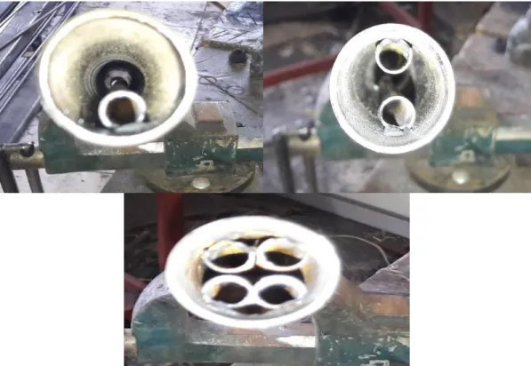
The TPCT type closed-end heat pipe discharged from the air by the air discharge machine, and then the heat pipe filled with water as working fluid at a ratio of 1/3 of the evaporator volume. The TPCT used is made of iron with the specifications as follows tube length 210 cm inner diameter 25 mm and a thickness of 1.5 mm. While, the internal structure of the TPCT pipe has been modified by adding small iron pipes in as it can be seen in Figure 3.2. The diameter and thickness of all the small tubes is equal. However, its length was different the internal diameter is 8 mm with thickness 1 mm. The small tubes on the upper side were 30 cm length, which will helps the hot steam of the evaporator raise up to the top of the condenser, while the second side on the lower side was 150 cm length, in order to helped condensed water to return to the evaporator.
Figure 3.3. Photograph showing the tubes used in the experiment.
Figure 3.5. Photograph showing internal modifications made on the heat pipe.
As it can be notice from the figure 3.4 and figure 3.5. The modifications and manufacturing has been designed as following, the first test was on a normal heat pipe without any modifications in manufacturing. The first type of the modification has been made by insert a small inner tube from the bottom in order to enable the water to returns to the evaporator after condensation process. Where with the second type another small tube was added in the upper region versus the one in the first type to pass the hot water vapor upward, so in this type two small tubes has been used, one upper and another lower tube. While, the final modification was almost similar to the second type with small change by adding two tubes, one upper and another lower will work as same as the second type, to be the number of small internal pipes used in this type is four.
With concerning to the calculation of TPCT performance, thermocouples have been installed in the investigation that will grant temperature readings through the points TE1, TE2, TC1 and TC2 as illustrated in figure 3.6. In addition to a double thermal installation to calculate the temperature of the water tank, and the tank is made of iron and contains 5 liters of water.
Figure 3.6. Schematic of the points installed thermocouples.
3.2. EXPERIMENT DESCRIPTION
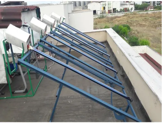
The results were found by setting the experimental system for this investigation at three different angles 26°, 41° and 56° to receive solar radiation of heat pipes of the type TPCT. The angles were the inclination on the horizontal as shown in figure 7.3 angle of 26°, figure 3.8 tilted at an angle of 41° and figure 9.3 where the pipes tilted at an angle of 56°.
Figure 3.7. Photograph showing the heat pipes receives solar radiation at an angle of 26°.
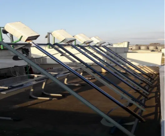
Figure 3.8. Photograph showing the heat pipes receives solar radiation at an angle of 41°.
Figure 3.9. Photograph showing the heat pipes receives solar radiation at an angle of 56°.
Can explain the working system of TPCT heat pipe, as this tube is empty from air, which contains clean water as a liquid to work in a predetermined quantity, when it receiving solar radiation, it has the property of rapid heating, as the water inside it quickly reaches a boiling state then it will transformed into a hot steam as results of the pressure increases and forces the steam to rise to touches the water in the tank and loses its heat extracted from the water tank. Thus, the steam condenses in the condenser and returns back to the evaporator due to gravity.
The internal structure of the TPCT has been modified by adding small internal pipes to help transfer steam to the reservoir water to be heated, and prevent loss of heat when hot steam rises to help return the water to the evaporator when condensed in the condenser.
The experiments were carried out with four-heat pipes TPCT type as shown in figure 4.3. Where the first tube was normal without any internal additions. While a small inner tube was added in the second tube with, the specifications described above and placed in the lower side which through it the water returns after condensation to the evaporator again. Small inner tube was added to the third tube of the test, as described above, its allocated to be fixed against the tube added in the second pipe of experiment to help the steam from passing to the condenser up, while the bottom small tube is working to return the water to the evaporator, similarly to the second pipe of experiment, thus reaching the water tank in try to tap all the heat without losing. However, The fourth tube a two small inner tubes its added, in addition to what was done in the third tube, one of the top and the other down to do the same work in the third tube to be the total internal pipes in this type were four tubes.
Experiments were carried out after these changes in the internal structure of the pipe, and heat exchangers were placed in the specified positions as in the figure 3.6 to obtain the desired temperatures, and also the pipes used to receive solar radiation and tilt were installed on the horizontal at different angles as shown in the previous above these angles are 26°, 41° and 56°. The temperatures on each type of pipe have taken at each bending angle as shown in the following tables.
PART 4
RESULTS AND DISCUSSION
The experiments were conducted under the climatic conditions at Samsun in Turkey. Where solar heat pipes TPCT are used with different internal structures, and placed at different angles 26°, 41° and 56°. The temperature was measured to performance evaluation of the pipe, the results data were taken at the time 07:00 am to 15:00 pm.
Figure 4.1. Temporal radiation intensity with different angles.
Figure 4.1 gives an information about the best time for the intensity of the temporal radiation of the three angles 26°, 41° and 56° that was between the 11:00 am until 15:00 pm. It is clear that the highest radiation value at angle 26° with a value was of 1098.3 W/m2 at 12:10 pm that was the highest radiation value recorded during the experiment. The highest radiation value at angle 41° was 954.6 W/m2 at 12:50 p.m., and the angle 56° was the highest radiation recorded at 13:00 p.m. with the result 849.8 W/m2.
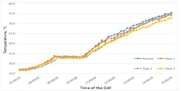
Figure 4.2 shows the temperatures obtained in the water tank for all types of heat pipes used in the experiment at a tilt angle of 26°. It can be notice that the temperatures increases along the time and the highest temperatures was recorded at 15:00 pm, the highest temperature was recorded from the heat pipe type2 with a value of 62.6 °C. Followed by the temperature of the heat pipe type1 with 59.8 °C. The temperatures of the heat pipe normal type and type 3 were recorded respectively 58.3 °C and 58.1 °C it was the lowest temperatures recorded.
Figure 4.2. Temperature of the water tank with various heat pipes at an angle of 26°.
Figure 4.3 shows the temperatures obtained in the water tank with all different heat pipes types have been used for this experiment, at a slope angle of 41°. Temperatures were somehow correlation with time, also the temperature is tend to slight fluctuate in the type1 along the time of the experiment. While the highest temperature of the heat pipe of type2 was 57.9 °C, followed by the heat pipe of normal type 56.9 °C, and then comes the heat pipe type1 with 56.2 °C, where type3 of heat pipe reach 55 °C, and all these temperatures were recorded at 15:00 pm.
Figure 4.4. Temperature of the water tank with various heat pipes at an angle of 56°.
Figure 4.4 shows the temperatures obtained in the water tank for all types of heat pipes used in the experiment at a tilt angle of 56°. The temperature increases with time, start 07:00 am to 08:50 am, and then exposed to a semi-stable situation between 08:50 am to 10:20 am. The temperature does not exceed the change between a decrease and increase of approximately one degree Celsius. However, an increase is start again at 10:20 am, and then it reaches its highest values at 15:00 pm. Where the highest temperature recorded with normal type of heat pipe at 55.5 °C, and the heat pipe of type1 recorded 54 °C. While the type2 of heat pipe reach 54.9 °C, and type3 of heat pipe is 52.8 °C.
Figure 4.5. Temperature of the water tank of the normal type heat pipe at angles 26°, 41°, 56°.
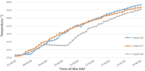
Figure 4.5 display the temperature of the water tank of the normal type heat pipe at the three angles 26°, 41° and 56°. It is clear from the figure that the highest temperature of this type of heat pipe obtained at an angle of 26° at 58.3 °C, while the lowest temperature obtained at an angle of 56° was 55.5 °C, where on the other hand the temperature obtained at the angle of 41° was it 56.7 °C. Knowing, the highest temperatures were recorded at 15:00 pm.
Figure 4.6. Temperature of the water tank of the type 1 heat pipe at angles 26°, 41°, 56°.
Figure 4.6 display the temperature of the water tank of the Type1 heat pipe at the three angles 26°, 41° and 56°. It is evident that the highest temperature recorded at 15:00 pm, was the highest temperature at angle 26° and recorded 59.8 °C, followed by the angle at 41° and reach 56.2 °C, while 54 °C recorded at an angle of inclination 56°.
Figure 4.7. Temperature of the water tank of the type 2 heat pipe at angles 26°, 41°, 56°.
Figure 4.7 display the temperature of the water tank of the type2 heat pipe at the three angles 26°, 41° and 56°. At 15:00 pm, the highest temperature was obtained with the highest value at angle 26° it was 62.6 °C, while the temperature was recorded at 9.57 °C when the angle was it 41°, where at an angle of 56° a temperature was 54.9 °C.
Figure 4.8. Temperature of the water tank of the type 3 heat pipe at angles 26°, 41°, 56°.
Figure 4.8 display the temperature of the water tank of the type3 heat pipe at the three selected angles. From the figure it is clear that the highest temperatures were recorded at an angle of 26°, and the lowest was at an angle of 56°, the highest temperatures were recorded at 15:00 pm as following at the angle 26° is 58.1 °C, angle 41° was 55 °C, while Recorded 52.8 °C at an angle of 56°.
Also, from the above, figure 4.5, figure 4.6, figure 4.7 and figure 4.8 its noticeable that the water temperature of the tank passes at all types of heat pipes at an inclination angle 56° in a seems to be in stable state. The stability state is starting at 08:50 am until 10:20 am, and during this period does not exceed the temperature change, whether low or rise by one degree Celsius, and then the temperature returns to rise naturally again. Figure 4.6 illustrates the temperature at the locations where the thermocouples were the placed along the normal type of heat pipe whish tilted at an angle of 26°. It is clear from the figure, that there is a temperatures spacing between the points of position along the pipe, where the highest temperature was recorded at the evaporator TE2 = 99.4 °C, the highest temperature at the condenser TC2 = 57.3 C°, and the temperature difference was significant between TE2 and TC2 at 15:00 pm, this difference is estimated at 39.9 °C. We observe fluctuation in temperature of TC1 along the time interval between decrease and sudden increase.
Figure 4.9. Temperatures at the thermocouple points on the along heat pipe of the normal type at an angle of 26°.
Figure 4.10. Temperatures at the thermocouple points on the along heat pipe of the type 1 at an angle of 26°.
Figure 4.10 illustrates the temperature at the locations where the thermocouples were the positioned along the type1 of heat pipe whish tilted at an angle of 26°. Where the temperature convergence is especially evident between TE1 and TE2, while still the fluctuation observed around TC1 temperatures, and the temperature difference between TE2, TC2 dropped to 33.7 °C at the highest temperature at 15:00 pm.
Figure 4.11 illustrates the temperature at the locations where the thermocouples were the located along the type2 of heat pipe whish tilted at an angle of 26°. For temperatures at 15:00 pm the difference was about 28.8 °C, while oscillation
![Figure 1.4. Flat plate collector [8].](https://thumb-eu.123doks.com/thumbv2/9libnet/5392354.101725/25.892.228.730.613.880/figure-flat-plate-collector.webp)
![Figure 2.1. Schematic of the working principle, with direction of the vapor and liquid flows [68]](https://thumb-eu.123doks.com/thumbv2/9libnet/5392354.101725/33.892.177.779.127.409/figure-schematic-working-principle-direction-vapor-liquid-flows.webp)
![Figure 2.3. Schematic of principle of operation of a loop heat pipe [77, 78].](https://thumb-eu.123doks.com/thumbv2/9libnet/5392354.101725/35.892.179.779.258.514/figure-schematic-principle-operation-loop-heat-pipe.webp)
![Figure 2.4. Schematic the forms of grooves present in the Grooved Heat Pipes [87].](https://thumb-eu.123doks.com/thumbv2/9libnet/5392354.101725/36.892.233.725.124.380/figure-schematic-forms-grooves-present-grooved-heat-pipes.webp)
![Ambrosius Aurelianus [called Emrys Wledig] (fl. 5th cent.), military leader](data:image/gif;base64,R0lGODlhAQABAIAAAP///wAAACH5BAEAAAAALAAAAAABAAEAAAICRAEAOw==)