Micromachinable ultrasonic leaky wave air transducers
F. Levent Degertekin,a)Abdullah Atalar,b)and Butrus T. Khuri-Yakub Edward L. Ginzton Laboratory, Stanford University, Stanford, California 94305-4085 ~Received 27 October 1997; accepted for publication 8 June 1998!
Ultrasonic air transducers using leaky waves on thin membranes are analyzed using perturbation and normal mode approaches. The transducers utilize the efficient coupling of ultrasonic energy to air through radiation of these leaky wave modes when their phase velocity is close to the sound speed in air. Theoretical results on optimum transducer dimensions and bandwidth estimation show that a minimum conversion loss of 8.7 dB with a 78% fractional bandwidth is possible. Common micromachining materials are shown to be suitable transducer materials and result in feasible devices. This is demonstrated by fabricating a 580 kHz transducer using a silicon membrane bonded to a ring of PZT-5H. With this configuration the transducer is self line focusing. Results of through transmission experiments on silicon and transmission images on paper are reported. © 1998 American Institute of Physics. @S0003-6951~98!00232-0#
Due to the large impedance mismatch between common piezoelectric materials and air, conventional piezoelectric transducers are not very efficient sources of ultrasound in air.1 The efficiency can be increased by matching layers at the expense of bandwidth. Recently, several micromachined capacitive transducers have been developed. The devices made by stretching metallic membranes over micromachined grooves in silicon provide wide bandwidth, however, their efficiency is low.2Efficient ultrasonic transmission up to 11 MHz is demonstrated using a resonant thin silicon nitride membrane over a sub-micron thick surface micromachined air gap.3,4 For wideband operation with these devices, dy-namic range should be sacrificed. Ultrasonic wave transmis-sion in air at 1 MHz using leaky waves has been demonstrated.5 In this letter, a simple theoretical model for these transducers to predict the optimum dimensions and the bandwidth is presented. The use of micromachining for the fabrication of efficient transducers in the MHz range is pro-posed and its feasibility is demonstrated using a self-focusing transducer made of silicon.
Any ultrasonic wave propagating on a solid surface ra-diates energy to the surrounding fluid medium if the phase velocity is larger than the velocity of sound in the fluid. Various calculation methods predict that the rate of this en-ergy transfer is maximized when the phase velocity of the mode approaches to that of the fluid.5,6 In Fig. 1 the phase velocity as well as the attenuation due to energy leakage of the lowest order antisymmetric Lamb waves (A0 mode! in free plates of common silicon micromachining materials are plotted as a function of the frequency thickness product~fd!. It is observed that the phase velocity of the A0 mode can be adjusted so that it is close to the sound speed in air~330 m/s! by changing the thickness of the membrane at a fixed fre-quency. For example, at 7 MHz, a 1mm thick silicon plate is required to match the sound speed in air. These thin films can be fabricated by micromachining, and have already been
used for this purpose.7 The phase velocity matching can be achieved using any solid with appropriate thickness. How-ever, the leak rate of ultrasonic energy is a function of the elastic properties, particularly the density of the plate mate-rial. For example, high density materials such as brass and steel have much lower leak rates. As expected, the leak rates have maxima when the phase velocity is close to 330 m/s, and they go to zero when the wave in the plate is subsonic in air. These figures, given in units of dB-l show that 50% of the power in the Lamb wave will be radiated to air in a distance of 5 l for a 1mm thick silicon at 7 MHz. Experi-ments confirm these theoretical leak rate calculations. So, once generated, the ultrasonic energy in the Lamb wave is transferred to air in a very short distance.
Since the transduction mechanism of the leaky wave transducers is a mode conversion process, it can be analyzed using the methodology developed for bulk mode to surface wave conversion with appropriate modifications.8 Referring to Fig. 2, we assume that the Lamb wave propagating with a phase velocity of Vp5Vair/sin(u) in the unbounded transmit-ter plate is leaking its energy at an angleu. The radiated field is received by an identical transducer of length l. The z com-ponent of the particle velocity at the transmitter surface has a variation
viz~x!5viz~0!e2 jbxe2ax, ~1!
a!Electronic mail: [email protected]
b!Department of Electrical and Electronics Engineering, Bilkent University, Bilkent 06533, Ankara, Turkey.
FIG. 1. A0 mode dispersion and leak rate curves of silicon~solid!, oxide ~dashed! and nitride ~dotted! membranes.
APPLIED PHYSICS LETTERS VOLUME 73, NUMBER 6 10 AUGUST 1998
741
where viz(0) is z component of the particle velocity at x 50 and b anda are the real and imaginary parts ~i.e., the leak rate! of the propagation constant in the x direction. Zair is the acoustic impedance of air. The total power radiated from the transducer can be found using the perturbation ap-proach and integrating the power lost per unit length from the surfaces of the plate from x50 to ` as
Pin5
uviz~0!u2Zair
2a cos~u! . ~2!
It has to be noted that only half of the input power will reach the receiver since half of it is lost from the other side of the transmitter plate. This power loss can be prevented by using plate/gap/substrate structures, which will not be discussed in this letter. The Lamb wave amplitude at the receiving plate due to this incident field can be found using the normal mode theory. The expression for the normalized field amplitude at a distance x is given as an~x!5 e2 jbxe2ax 2 Pnn
E
0 x ejbx8e2ax8 3@vzt*Tzt~x8
!2v*zbTzb~x8
!#dx8
. ~3!In this equation vzt and vzb are the normal component of
particle velocity at the top and bottom surfaces of the plate. The incident normal stress field is denoted by Tzt(x
8
) and Pnn is the total power per unit width carried by the mode. Since for an antisymmetric modevzt5vzb Tzt52Tzb, ~4!
the mode amplitude of the Lamb wave at a distance l can be written as
an~l!5
e2 jble2allvzt*viz~0!Zair
2 Pnn cos~u! . ~5!
Using the relation between the mode amplitude and power, the output power in the Lamb wave can be written as
Pout~l!5uan~l!u2Pnn5l2e22al
uvztu2uviz~0!u2Zair 2 4 Pnn cos~u!2
. ~6! The leak rate of a Lamb wave mode can be expressed in terms of the mode variables as
a5 uvztu2Zair
2 Pnn cos~u!. ~7!
Note that the leak rate is doubled as compared to a surface wave since the plate is perturbed by the fluid at both surfaces of the plate. Substituting this expression in Eq. ~6!, the out-put power can be found in terms of the transducer dimension and the leak rate
Pout~l!5
al2e22alZairuviz~0!u2
2 cos~u! . ~8!
To find the optimum dimension of the transducer, the two-way efficiency is defined as the ratio of the output power to total input power. This results in the expression
h~al!5~al!2e22al ~9!
for the two-way efficiency. Differentiating with respect to
al, the maximum efficiency is found as
hmax50.135 when al51~l51/a!. ~10!
At this optimum value the two way loss is about 8.7 dB, which shows the high efficiency of the transducer. The varia-tion of efficiency as a funcvaria-tion of transducer length is plotted in Fig. 3. The important conclusion is that the leak rate of the Lamb wave can be high enough so that the transducer has a
FIG. 3. Variation of the efficiency of the leaky wave transducer with trans-ducer length-leak rate product.
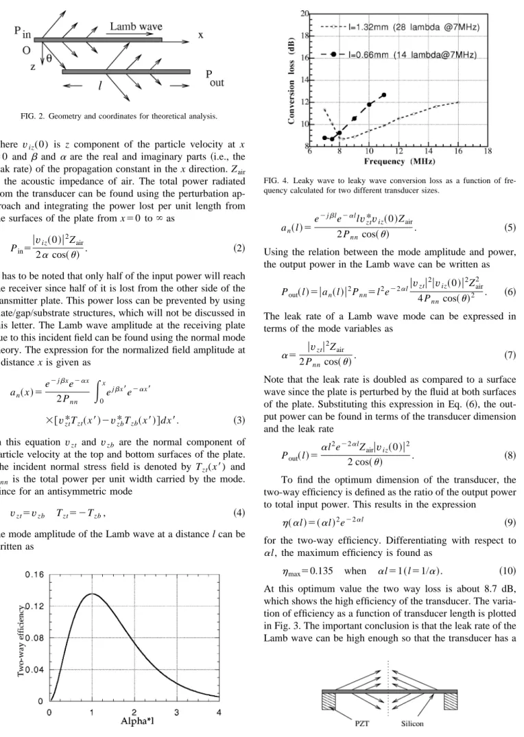
FIG. 4. Leaky wave to leaky wave conversion loss as a function of fre-quency calculated for two different transducer sizes.
FIG. 5. Schematic of the self-line-focusing leaky wave transducer. PZT diameter is 2.3 cm and it is 1.3 mm thick.
FIG. 2. Geometry and coordinates for theoretical analysis.
feasible dimension with reasonable insertion loss level. In case of a 1mm thick silicon transducer the optimum dimen-sion is about 14l ~0.66 mm! at 7 MHz, which can be easily micromachined. Using Figs. 1 and 3 one can find the band-width of a transducer for a given dimension. In Fig. 4 the insertion loss of a 1mm thick silicon transducer is plotted as a function of frequency. The optimum dimension of 0.66 mm at 7 MHz results in a 35% fractional bandwidth. Using a larger transducer one can achieve larger bandwidths avoiding the low frequency cutoff in the subsonic regime. As an ex-ample, a 1.32 mm transducer can have a 78% fractional bandwidth, which is appropriate for many pulse echo appli-cations.
A leaky wave transducer is constructed using an 18mm thick~001! silicon plate which is epoxy bonded to a radially polarized PZT-5H ring as shown in Fig. 5. With this configu-ration the device has 15% fractional bandwidth around 580 kHz and 55 dB insertion loss. The suboptimum dimension of the transducer results in 12.5 dB leaky wave conversion loss and the rest can be attributed to the electrical mismatch and imperfections in fabrication. The Lamb waves generated at the PZT-silicon contact converge to the center of the plate while leaking ultrasonic waves to air. This results in a self line focusing device as used in acoustic microscopy.9In Fig. 6, the upper trace shows the transmitted signal when two transducers are facing each other at a 9 mm distance. The lower trace is the through transmission signal when an 18
mm thick silicon plate is inserted between the transducers. The signal loss is only 17 dB, which is 29 dB less than the impedance mismatch loss. This is due to the efficient mode conversion between the incident pressure waves in the air and the Lamb waves in the silicon plate which leak back into the air and are collected by the receiver. Mode conversion due to the finite aperture of the transducer improves trans-mission through a 25mm thick steel or brass shims and 100
mm thick copy paper by about 17 dB enabling transmission
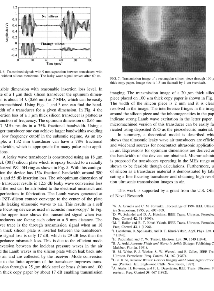
imaging. The transmission image of a 20 mm thick silicon piece placed on 100mm thick copy paper is shown in Fig. 7. The width of the silicon piece is 2 mm and it is clearly resolved in the image. The interference fringes in the image, around the silicon piece and the inhomogeneities in the paper indicate strong Lamb wave excitation in the letter paper. A micromachined version of this transducer can be easily fab-ricated using deposited ZnO as the piezoelectric material.
In summary, a theoretical model is described which shows that ultrasonic leaky wave air transducers are efficient and wideband sources for noncontact ultrasonic applications in air. Expressions for optimum dimensions are derived and the bandwidth of the devices are obtained. Micromachining is proposed for transducers operating in the MHz range and shown to be feasible though calculations. Furthermore, use of silicon as a transducer material is demonstrated by fabri-cating a line focusing transducer and obtaining high resolu-tion ultrasonic transmission images in air.
This work is supported by a grant from the U.S. Office of Naval Research.
1W. A. Grandia and C. M. Fortunko, Proceedings of 1994 IEEE Ultrason-ics Symposium, 1995, pp. 697–709.
2
D. W. Schindel and D. A. Hutchins, IEEE Trans. Ultrason. Ferroelectr. Freq. Control 42, 51~1995!.
3M. I. Haller and B. T. Khuri-Yakub, IEEE Trans. Ultrason. Ferroelectr. Freq. Control 43, 1~1996!.
4
I. Ladabaum, D. Spolianski, and B. T. Khuri-Yakub, Appl. Phys. Lett. 68, 7~1996!.
5H. Dabirikhah and C. W. Turner, Electron. Lett. 30, 1549~1994!. 6B. A. Auld, Acoustic Fields and Waves in Solids~Krieger Publishing Co.,
Malabar, Florida, 1991!. 7
R. M. White, P. J. Wicher, S. W. Wenzel, and E. Zelles, IEEE Trans. Ultrason. Ferroelectr. Freq. Control 34, 162~1987!.
8G. S. Kino, Acoustic Waves: Devices Imaging and Analog Signal
Process-ing~Prentice Hall, Englewood Cliffs, New Jersey, 1987!.
9
A. Atalar, H. Koymen, and F. L. Degertekin, IEEE Trans. Ultrason. Fer-roelectr. Freq. Control 39, 667~1992!.
FIG. 6. Transmitted signals with 9 mm separation between transducers with and without silicon membrane. The leaky wave signal arrives after 60ms.
FIG. 7. Transmission image of a rectangular silicon piece through 100mm thick copy paper. Image size is 1.5 cm~lateral! by 1 cm ~vertical!.
743