Kazan Federal University, Institute of Fundamental Medicine and Biology, 18 Kremlyovskaya St., 420008 Kazan, Russian Federation
*
S Supporting InformationABSTRACT: Template-directed synthesis of nanomaterials can provide benefits such as small crystalline size, high surface area, large surface-to-volume ratio, and structural stability. These properties are important for shorter distance in ion/electron movement and better electrode surface/electrolyte contact for energy storage applications. Here nanostructured FePO4cathode materials were synthesized by using peptide nanostructures as a template inspired by biomineralization process. The amorphous, high surface area FePO4nanostructures were utilized as a cathode
for lithium-ion batteries. Discharge capacity of 155 mAh/g was achieved at C/20 current rate. The superior properties of
biotemplated and nanostructured amorphous FePO4are shown compared to template-free crystalline FePO4.
KEYWORDS: peptide amphiphile, self-assembly, hydrogel, nanofiber, nanobelt, template-directed materials
■
INTRODUCTIONHigh demand for portable electronic devices and electric and hybrid vehicles has increased the need for secondary batteries in the past decade. Lithium-ion batteries (LIBs) are currently the most prevalent secondary battery systems due to their high energy density, high voltage, light weight, and long cycle life.1−4 Selection and synthesis of the electrode materials are very crucial to utilize these properties appropriately. Lithium transition metal oxides (LiMOx, M is a transition metal) are conventionally used as cathode materials for LIBs; however, there are some safety concerns associated with these materials, because they release oxygen from the lattice at high temperatures.5To increase the safety of cathode materials, materials with polyanion groups have been investigated.6−8 On the one hand, olivine lithium iron phosphate (LiFePO4) has been studied as cathode material due to its high stability and thermal safety, good theoretical capacity (∼170 mAh/g), and low material cost.9−11On the other hand, olivine structure has slow Li+ion and electron transfer, which leads to a poor rate capability.12,13Alternatively, amorphous iron phosphate (FePO4) has received increasing attention because it
is stable, safe, cheaper, and has a slightly higher theoretical capacity (∼178 mAh/g).14 Moreover, it has a continuous charge−discharge voltage profile, which makes it easier to monitor the state of charge of the battery.4 However, as amorphous FePO4 suffers from low ionic and electronic
conductivity, its practical capacity is dramatically lower than the theoretical value.15,16Several attempts have been shown to be effective such as nanostructures,17−19 carbon nanopainting,20 and conductive additives.21,22 By using template-directed synthesis methods, nanostructures with desired shape, size, and
function can be achieved.23−25These materials usually have small crystalline size, high surface area, large surface-to-volume ratio, and favorable structural stability, which result in shorter distance for ion/electron movement and better electrode surface/ electrolyte contact.26 All these properties eventually lead to higher overall capacity, rate capability, and battery life.
Biotemplating is an efficient way to synthesize environ-mentally friendly, ordered, and reproducible materials.27 Biomineralization process was previously utilized for reaching these targets.27,28 Previously, crystalline FePO4 hollow nano-spheres with diameters of 7μm were produced by using rape pollen grains as a template, but their electrochemical perform-ance was not studied.27 Amorphous FePO4 nanowires with
diameters of 10 to 20 nm were synthesized by using genetically engineered M13 virus, showing an initial specific capacity of 100 mAh/g at a current rate of C/10. A heterostructured cathode material mixed with AgCl was synthesized by using biotemplat-ing approach, and their discharge capacity was increased to 150 mAh/g after cycling at the same current rate.28
In this work, we show synthesis of nanobelt- and nanotube-shaped iron phosphate (FePO4) nanostructures by using peptide
nanostructures as biotemplates. By exploiting the fascinating features of the amphiphilic peptide molecules such as ease of modification over the chemical functionality and architecture diversity,29the nanonetworks were uniformly coated with a thin FePO4(∼8 nm) layer allowing the Li+ions to intercalate through
Received: February 29, 2016 Accepted: June 17, 2016 Published: June 17, 2016
Downloaded via BILKENT UNIV on December 23, 2018 at 11:07:51 (UTC).
shorter distances, to increase the electrochemical reaction kinetics and to reduce the concentration polarization effects. The FePO4coated peptide nanonetworks were later calcined to
remove the organic peptide template. Furthermore, multiwalled carbon nanotubes (MWCNTs) were mixed with the calcined
FePO4nanostructures to improve the electronic conductivity of
the cathodefilms.
■
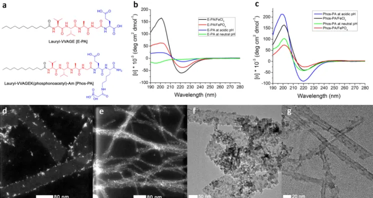
RESULTS AND DISCUSSIONTwo different peptide amphiphile molecules containing a hydrophobic alkyl tail, a short peptide sequence forming β-Figure 1.(a) Chemical structures of peptide amphiphile molecules. CD spectra of the secondary structure of peptide amphiphile interactions (b) E-PA and (c) Phos-PA. STEM and TEM images of self-assembled peptide amphiphiles with inorganic materials (d) STEM image of E-PA/FeCl3, (e) STEM
image of Phos-PA/FeCl3, (f) TEM image of uncalcined ETF, and (g) TEM image of uncalcined PTF.
Figure 2.Morphology and composition of the calcined peptide nanostructures coated with inorganic materials. (a) TEM image of E-PA/FePO4(ETF),
(b) SEM image of ETF, (c) EDX spectrum of ETF, (d) TEM image of Phos-PA/FePO4(PTF), (e) SEM image of PTF, and (f) EDX spectrum of PTF. ACS Applied Materials & Interfaces
sheet structure, and a charged headgroup were designed and synthesized. These peptide amphiphile molecules, VVAGEK(phosphonoacetyl)-Am [Phos-PA] and Lauryl-VVAGE [E-PA], can form nanostructures, and they were used as a template for FePO4formation (Figure 1a). The purity of the
peptide molecules was determined by using liquid chromatog-raphy−mass spectrometry analysis (Figure S1−S4,Supporting Information). The self-assembly of the peptides was triggered by Fe3+ addition, which results in the formation of β-sheet
secondary structure that is essential for the formation of organic−inorganic core−shell materials. In addition, the func-tional groups at the periphery of the peptide nanostructures coordinate to Fe3+ ions providing the nucleation sites for the
growth of the inorganic material on the surface of the nanostructures. Template-free (bulk) FePO4was also
synthe-sized by mixing the precursor materials in absence of the peptides. Electrochemical performance of the bulk material was analyzed and compared to those of the templated materials.
A gel was formed when peptide molecules self-assembled into nanostructures (Figure S5). The 1 wt % E-PA/FeCl3and
Phos-PA/FeCl3 gels were mixed with NaH2PO4 to induce the
formation of E-PA/FePO4(ETF) and Phos-PA/FePO4(PTF). The secondary structures of the self-assembled peptides were studied by using circular dichroism (CD) spectroscopy. Formation of β-sheet structure for all of the self-assembled systems was observed (Figure 1b,c).30,31The E-PA solution at physiological pH shows the formation of random coil with least signal at 195 nm. The random coil structure of E-PA disappears and transforms intoβ-sheet structure either by lowering the pH or by introducing the iron ions due to the self-assembly process. The CD results also prove the self-assembly of Phos-PA molecules at pH 7 due to the presence ofβ-sheet structural motif. The transmission electron microscopy (TEM) images of both self-assembled E-PA and Phos-PA after addition of FeCl3
revealed nanostructure formation. On the one hand, the E-PA and FeCl3complex forms one-dimensional (1-D) nanobelt with
a width of 60 nm (Figure 1d). On the other hand, the mixture of Phos-PA and FeCl3forms 1-D nanofiber with a diameter of 10
nm (Figure 1e). The β-sheet conformation in both self-assembled Phos-PA and E-PA systems contributed to the nanofiber and nanobelt formation. Glutamic acid side chain plays a major role in the self-assembly of the E-PA molecule. In addition, the nanobelt structure is related with highly effective packing amongβ-sheets with peptide segments leading to the loss of curvature in the aggregate.32The CD spectra support the β-sheet content of the E-PA/FeCl3that is higher than the E-PA
forming nanofiber at acidic pH (Figure S6). On the one hand, the ETF shows inorganic material covering the 1-D peptide nanobelts (Figure 1f). On the other hand, the PTF forms nanofibers with inorganic FePO4on the surface of the peptide
nanofiber core (Figure 1g).
Calcination was performed to obtain amorphous forms of anhydrous FePO4that has better capacity and cyclability than trigonal, hexagonal, and hydrated FePO4.
33
After calcination of ETF, on the one hand, the FePO4 nanobelts were sintered
(Figure 2a). On the other hand, the organic−inorganic core− shell nanofibers of PTF were transformed into nanotubes due to the decomposition of organic template. The average wall thickness of PTF nanotube after calcination is∼8 nm (Figure 2d). High-resolution TEM images of both samples show the presence of amorphous surface (Figure S7).
The morphology of both calcined and uncalcined ETF and PTF samples were also confirmed by using E-SEM (Figures 2b,e andS8). After calcination, the network is thoroughly preserved as shown in the SEM micrographs. The EDX spectra of the calcined FePO4-coated peptide nanostructures show Fe, P, and O peaks in
EDX spectrum of both samples (Figure 2c,f). For calcined ETF, Figure 3.(a) Discharge−charge voltage profiles of the initial seven cycles of the ETF at C/20. (b) Discharge−charge voltage profiles of the initial seven cycles of the PTF at C/20. (c) The rate capability of the cathode materials, and (d) the cyclic stability of the discharge capacity of the cathode materials. ETF and PTF were tested at C/2 current rate; bulk FePO4was tested at C/5 current rate.
the Fe/P atomic ratio is found to be 0.92, and the Fe/P atomic ratio of calcined PTF is 0.99.
The FT-IR analysis was performed to understand the interactions in the organic−inorganic core−shell materials (Figure S9). The uncalcined ETF, uncalcined PTF, calcined ETF, calcined PTF, and template-free (bulk) FePO4show peaks,
which belong to peptide and iron phosphate. Crystallinity of the organic−inorganic core−shell materials was analyzed by using X-ray diffractometer (XRD). A broad peak was observed for each sample: uncalcined ETF, uncalcined PTF, calcined ETF, and calcined PTF indicating the presence of amorphous phase in all samples (Figure S10a). The purity of the crystalline FePO4was proved by heating both ETF and PTF until 600°C for 2 h to form crystalline FePO4. The patterns of crystalline structure of
FePO4according to the reference from ICSD hexagonal FePO4
code 01−084−0875 were observed from the FePO4 samples
(Figure S10c,d).34The X-ray photoelectron spectroscopy (XPS) was used to characterize organic−inorganic core−shell peptide and FePO4 nanostructures. XPS spectra of uncalcined and
calcined FePO4samples show peaks corresponding to Fe 2p, Fe 3p, O 1s, N 1s, C 1s, P 2s, and P 2p (Figures S11−S13).
A thermogravimetric analysis was performed to determine the quantity of organic and inorganic materials in uncalcined ETF and PTF (Figure S14). Both of the template-directed FePO4
materials before calcination consist of nearly 65% of inorganic materials. Inductively coupled plasma−mass spectrometry (ICP-MS) analyses were also conducted to determine the amount of FePO4in each calcined sample. The iron phosphate content in 1 mg of each of the calcined E-PA/FePO4, Phos-PA/FePO4, and
template-free FePO4 are found to be 80.65%, 67.46%, and
71.54%, respectively. The FePO4 amount in each calcined
powder was used for calculating the weight of the active material in the cathode material to obtain the capacity value.
Electrochemical performances of the template-grown FePO4 cathodes were studied with discharge−charge tests in the voltage range of 2.0−4.0 V (Figure 3). The discharge−charge curves at different current rates for all of the materials were given in detail inFigures S15−S17, in which thefirst charge capacity of the ETF was also shown up to completion. The ETF, the PTF, and the bulk template-free FePO4revealed first discharge capacities of
116, 106, and 18 mAh/g at C/20 current rate, respectively (Figures 3a,b and S17a). Clearly, the template-grown FePO4 materials yielded significantly greater discharge capacities (around sixfold discharge capacity increase for the ETF and the PTF). All materials showed high charge capacities and a charge plateau at∼3.35 V in the first few cycles at a current rate of
C/20, indicating presence of some side reactions, which results in low Coulombic efficiencies. These reactions can potentially occur with water molecules35and side products (Figures S10− S13) formed during the synthesis. The reactions are less pronounced in the templated materials than in the bulk material, as the peptide templates restrain the formation of oxides/ hydroxides by electrostatically attracting the Fe3+cations to form
well-arranged FePO4 nucleation sites.33 Furthermore, the
discharge capacity of the ETF increased to 127 mAh/g, it stayed the same for the PTF after seven cycles at C/20 current rate, while it was 24 mAh/g at C/20 for the bulk FePO4.
The rate capabilities of the materials were studied with current rates of C/10, C/5, and C (Figure 3c). The rate capability of the PTF was observed to be superior to that of the ETF. The PTF sample yielded average discharge capacities of 117, 92, and 28 mAh/g in each current rate, respectively. In the ETF, the average discharge capacities were 108, 76, and 21 mAh/g, respectively, while they were 26, 18, and 7 mAh/g for the bulk FePO4. The
poor rate capability behavior as well as the low discharge capacities of the bulk are related to the long Li-ion intercalation distances, low surface-to-volume ratio, which results in lower electrochemical reactivity and also lower areal contact with the electronic conductor MWCNT in the bulk. The bioinspired growth method successfully overcomes most of these problems, as it provides smaller particle size. Moreover, the 1-D peptide nanobelt template of the ETF, which had a 60 nm width (Figure 1d), was sintered after the calcination process, while 1-D nanofiber template of PTF, whose diameter was 10 nm (Figure 1e), decomposed upon calcination and formed nanotubes of templated FePO4, which had a wall thickness of 8 nm (Figure 2d). As a result, the particle size in the PTF is smaller than in the ETF, and the phosphate groups present on the Phos-PA molecules provide enhanced order during deposition of FePO4.
The ordered structure and the reduced length of Li+ ion transportation path provides superior electrochemical perform-ance to the PTF. Furthermore, note that the decrease in the discharge capacities of the templated materials at higher current rates could be related to the reducing effect on the electronic conductivities of the materials due to the remaining organic species after calcination.
To understand the stability of prepared materials at high current rate, the cells were tested with C/20 current rate forfive cycles after the rate capability measurements. The capacity increased to 135, 137, and 27 mAh/g for the PTF, the ETF, and the bulk FePO4, respectively. The enhancement in the capacity at
the same current rate is attributed to the surface activation and Figure 4.Five cycles of the templated FePO4at a current rate of C/20 with higher potential ranges. (a) ETF nanobelt at 2−4.2 V, (b) PTF nanotube 2−
4.3 V.
tests, respectively. The average Coulombic efficiencies for the ETF, the PTF, and the bulk were 91.7%, 95.9%, and 83%, respectively (Figure S18). Clearly, the effect of the reduced size increased the reversibility of the electrochemical reaction. Furthermore, the ETF showed an increased trend in the Coulombic efficiency, while the PTF had a rather higher and stable value. This observation supports that the structure of the ETF becomes more ordered upon cycling as mentioned before, while the PTF retains its order from the beginning.
The stability and the performance of the ETF and the PTF samples were further tested at C/20 current rate with higher potential ranges of 2−4.2 V and 2−4.3 V, respectively, which are frequently used cutoff potentials in the literature in addition to 2−4 V potential range (Figure 4).28,36The discharge capacity of the templated nanotubular FePO4(PTF) was increased to 155 mAh/g, which is higher than its initial capacity with the low potential range (2−4 V) at C/20 current rate (106 mAh/g). These results further prove that the capacity increases gradually with surface activation. The discharge capacity of the templated nanobelt-shaped material (the ETF), however, was 117 mAh/g after five cycles, which shows that the material has a lower electrochemical stability compared to the PTF.
When the performance of the biomineralized FePO4 nanostructures was compared to previous reports,28 the PTF showed better overall discharge capacities than the M13 virus-templated FePO4(before AgCl addition). In another example,32
the amorphous LiFePO4(∼102 mAh/g at C/100 current rate) prepared with a solution-based synthesis had lower capacity than the ETF and the PTF samples. The discharge capacities, rate capabilities, cycling stabilities, and the Coulombic efficiencies of the biotemplated materials are far better than those of the bulk material. Even though the discharge capacity of the PTF was initially slightly lower than that of the ETF, it showed a better performance at higher current rates, and because of its increasing capacity trend, it revealed a higher discharge capacity at the same current rate (C/2), eventually. Superior performance of the PTF compared to the ETF is attributed to the high surface area of the PTF and chemical characteristics of the peptide nanofibers. Since the Phos-PA peptide contains phosphate groups on the periphery of the nanofibers, the chemical deposition of the FePO4is more favorable on the phosphate groups, which is more efficient than the E-PA peptide molecule.
■
CONCLUSIONIn summary, biotemplated amorphous FePO4 nanostructures
with an average wall thickness of 8 nm were synthesized. Significant improvement was observed in the electrochemical performances of the biotemplated materials compared to template-free FePO4due to nanoscale features with controlled
morphology. Biotemplated synthesis method provides an easy, environmentally friendly, cost-efficient, and novel way to
(DMC) were purchased from Sigma-Aldrich. All other chemicals were purchased from Fisher, Merck, Alfa Aesar, Sigma-Aldrich, Dupont, Celgard, or Whatman and used as received, without any further purification.
Peptides Synthesis. Peptide amphiphile molecules were synthe-sized manually using the method of standard solid peptide synthesis. Two peptide amphiphile molecules, which were E-PA (Lauryl-VVAGE) and Phos-PA (Lauryl-VVAGEK(phosphonoacetyl)-Am), were synthe-sized on Fmoc-Glu(OtBu)-Wang resin and MBHA Rink Amide resin, respectively. Before attaching thefirst amino acid residue to the resin, the Fmoc protecting group on the resin was removed by treating the resin with 20% (v/v) piperidine/dimethylformamide (DMF) solution for 20 min. Amino acid couplings were performed by pouring amino acid solutions containing 2 equiv of N-protected amino acid activated with 1.95 equiv of HBTU and 3 equiv of diisopropylethylamine (DIEA) for 1 equiv mol of resin and agitated for at least 2 h. For Phos-PA, the protecting group (Mtt) at the end of lysine side chain was removed by using 10 mL of 3.25% trifluoroacetic acid (TFA), 0.125% water, 0.125% triisopropylsilane, and 96.5% dichloromethane (DCM). Phosphono-acetic acid that was diluted in DMF together with DIEA and HBTU was poured into the vessel and mixed for 1 d to bind to the side chain of the lysine. Finally, each peptide was cleaved from the resin using a solution of 95% TFA, 2.5% water, and 2.5% triisopropylsilane for 2 h. The removal of excess TFA and DCM from the peptide solution was performed by using rotary evaporation. The peptide solution inside of round-bottomflask was dispersed in cold diethyl ether overnight. The peptide amphiphile was separated from diethyl ether by centrifugation. The centrifugate was dissolved in ultrapure water, frozen at−80 °C, and then lyophilized. The peptide was purified by using preparatory high-performance liquid chromatography (HPLC) before use. Purity of the peptide was ca. 98%.
Templated Iron Phosphate Preparation. Each of the peptide amphiphiles (1 mg) was dissolved in 90μL of ultrapure water to form peptide solutions. The peptide gels were formed by dropping 10μL of iron chloride solution (FeCl3) onto the peptide solutions. Each gel was
then immersed in iron chloride solution and transferred to ultrapure water to remove the excess iron solution on the gel before immersing into sodium phosphate (NaH2PO4) solution. The gels were again
washed with ultrapure water. These steps were repeated for four cycles. All of the processes were performed at low temperature (4 °C) to suppress the hydrolysis of Fe3+ions. The gels of E-PA/FePO
4(ETF)
and Phos-PA/FePO4 (PTF) were dehydrated using ethanol before
transferring into critical point dryer to produce aerogels. The thermal treatment (calcinations) was performed to the aerogels step by step in normal air atmosphere. The temperature was increased with a heating rate of 5°C/min until 250 °C and then brought to 350 °C with heating rate of 1°C/min. The samples were kept at 350 °C for 1 h. Template-free FePO4was also prepared by mixing FeCl3and NaH2PO4and kept
inside the oven at 80°C overnight. The wet powder was calcined by the same procedure as the templated iron phosphate.
Lithium-Ion Battery Preparation. Templated FePO4 cathode films were produced with two different organic templates and tested against lithium metal electrode in Swagelok type cells. The cathodefilm was obtained by slurry casting, in which the FePO4powder was ground
together with MWCT. Afterward, Nafion binder was dropped to the mixture powder. The composition of the mixture according to the total mass of the mixture was 7:2:1 for FePO4, MWCT, and Nafion,
respectively. The mixture was dispersed in isopropanol and stirred for a couple of days using magnetic stirrer. The mixture solution was casted on a separator (Celgard)film with doctor blade technique to yield the desired thickness. The castedfilm was first dried in room temperature for 1 h, and then the drying process was continued at 60°C for 8 h. The average cathodefilm weight for the all the materials was ∼1.0 mg. Stainless steel current collectors and two different separators were used (Celgard separator at the Li anode and Glassfiber/C separator at the cathode side). 280μL of 0.5 M LiTFSI in EC-DMC (1:1) was used as electrolyte. After the cell was assembled in the Ar atmosphere, it was sealed to prevent the interaction with the atmosphere. The cells were rested at room temperature for 8 h prior to testing.
Liquid Chromatography−Mass Spectrometry. Analytical LC-MS measurements were performed using Agilent Technologies 6530 Accurate-Mass Q-TOF LC-MS with electrospray ionization (ESI) source. Agilent Zorbax Extend-C18 column was used together with mixture of two different solutions of 0.1% (v/v) ammonium hydroxide− water (A) and 0.1% (v/v) ammonium hydroxide−acetonitrile (B). Liquid chromatograms were obtained at 220 nm.
Circular Dichroism. The secondary structure of the peptide nanostructures was determined by using JASCO J815 CD spectrometer at room temperature. One millimeter path quartz cuvette was used to perform the measurements. Aliquots (300 μL) of diluted peptide solutions were added into quartz cell and measured from 300 to 190 nm, with data interval and data pitch of 0.1 nm, scanning speed of 100 nm/ min, and three times of accumulations. Digital integration time was selected as 1 s, bandwidth as 1 nm, and sensitivity as standard.
Environmental-Scanning Electron Microscopy. The morphol-ogy of the fabricated samples was visualized by using FEI Quanta 200 FEG environmental scanning electron microscope with an ETD detector. The samples were sputter coated with 8 nm of gold/palladium prior to imaging. The EDX spectra of the samples were collected from the area at 300× magnification of the noncoated samples to obtain the chemical composition. The quantification of the EDX spectra was made to obtain the Fe/P ratio in the samples.
Transmission Electron Microscopy and Scanning Electron Microscopy. The diluted samples were casted on a Lacey mesh ultrathin carbon-coated copper grid and observed by FEI Tecnai G2 F30. Negative staining was performed using 2% (w/v) uranyl acetate for samples that did not contain any inorganic residue to get better contrast images.
Thermal Gravimetric Analysis. The percent composition of inorganic content in templated FePO4samples was determined by using
a thermogravimetric analyzer (TGA; Q500, TA Instruments). The temperature was ramped from 25 to 500°C with 10 °C min−1heating rate in the presence of N2gas. N2gas was switched to O2gas after the
temperature reached 500°C. The heating process was continued until 800°C with the same heating rate.
Fourier Transform Infrared Spectroscopy. Qualitative analysis of the samples was performed by analyzing the infrared absorption spectrum of each sample to learn the interaction inside the samples. KBr pellet was prepared prior to measurement. Bruker Vertex 70 FT-IR spectrometer was used for FT-IR analysis with wavenumber range from 4000 to 400 cm−1.
X-ray Diffractometer. The crystal structure of the samples was studied by using PAN analytical X’Pert X-ray diffractometer with Cu Kα radiation. The sample powders were scanned in the range of 2θ = 10− 60° and step size of 0.026°.
X-ray Photoelectron Spectroscopy. The surface characterization of organic−inorganic core−shell samples was done by using a Thermo Scientific K-Alpha XPS spectrometer with Al Kα monochromatic (100− 400 eV range) X-ray source and ultrahigh vacuum (∼10−9 torr).
Inductively Coupled Plasma−Mass Spectrometry. The iron content in the samples was determined by using Thermo Scientific X Series 2 ICP-MS. The iron amount was used to calculate the percentage of iron phosphate in the sample. Five different concentrations of iron reference solutions (50, 100, 250, 500, and 1000 ppb) were prepared from 1000 ppm iron standard solution.
Multichannel Battery Testing System. Electrochemical testing of the cells was performed with a Landt CT2001A multichannel
potentiostat/galvanostat. Five discharge/charge cycles are applied to the cell with current rates of C/20, C/10, C/5, and C, while the voltage wasfirst limited to 2.0−4.0 V; then, new voltage ranges of 2.0−4.2 and 2.0−4.3 V were utilized.
■
ASSOCIATED CONTENT*
S Supporting InformationThe Supporting Information is available free of charge on the
ACS Publications websiteat DOI:10.1021/acsami.6b02528. Detailed description of the LC-MS chromatograms; gel formation of peptides under different conditions; trans-mission and scanning electron micrographs of self-assembled peptide amphiphiles; FT-IR, XRD, and XPS data of templated and template-free FePO4; TGA of as-synthesized FePO4; charge and discharge curve of FePO4
samples; Coulombic efficiencies of templated FePO4. (PDF)
■
AUTHOR INFORMATIONCorresponding Authors
*E-mail:[email protected]. (M.O.G.) *E-mail:[email protected]. (E.Y.) Present Address
§Division of Biological and Environmental Sciences and
Engineering, King Abdullah University of Science and Technology, Thuwal 23955−6900, Kingdom of Saudi Arabia. Notes
The authors declare no competingfinancial interest.
■
ACKNOWLEDGMENTSThis work was partially funded by TUBITAK Grant No. 113M900. We thank Dr. A. Shaikh for help in peptide synthesis and M. Guler for TEM imaging.
■
REFERENCES(1) Tarascon, J. M.; Armand, M. Issues and Challenges Facing Rechargeable Lithium Batteries. Nature 2001, 414 (6861), 359−367.
(2) Armand, M.; Tarascon, J. M. Building Better Batteries. Nature 2008, 451 (7179), 652−657.
(3) Chen, J. S.; Archer, L. A.; Wen Lou, X. SnO2Hollow Structures and
TiO2Nanosheets for Lithium-Ion Batteries. J. Mater. Chem. 2011, 21
(27), 9912−9924.
(4) Yin, Y.; Hu, Y.; Wu, P.; Zhang, H.; Cai, C. A Graphene-Amorphous FePO4Hollow Nanosphere Hybrid as a Cathode Material for Lithium
Ion Batteries. Chem. Commun. 2012, 48 (15), 2137−2139.
(5) Cho, J.; Kim, Y. J.; Kim, T.-J.; Park, B. Enhanced Structural Stability of o-LiMnO2by Sol−Gel Coating of Al2O3. Chem. Mater. 2001, 13 (1),
18−20.
(6) Recham, N.; Chotard, J. N.; Dupont, L.; Delacourt, C.; Walker, W.; Armand, M.; Tarascon, J. M. A 3.6 V Lithium-Based Fluorosulphate Insertion Positive Electrode for Lithium-Ion Batteries. Nat. Mater. 2010, 9 (1), 68−74.
(7) Kang, K.; Meng, Y. S.; Bréger, J.; Grey, C. P.; Ceder, G. Electrodes with High Power and High Capacity for Rechargeable Lithium Batteries. Science 2006, 311 (5763), 977−980.
(8) Ji, X.; Lee, K. T.; Nazar, L. F. A Highly Ordered Nanostructured Carbon-Sulphur Cathode for Lithium-Sulphur Batteries. Nat. Mater. 2009, 8 (6), 500−506.
(9) Padhi, A. K.; Nanjundaswamy, K. S.; Goodenough, J. B. Phospho-Olivines as Positive-Electrode Materials for Rechargeable Lithium Batteries. J. Electrochem. Soc. 1997, 144 (4), 1188−1194.
(10) Wu, X.-L.; Jiang, L.-Y.; Cao, F.-F.; Guo, Y.-G.; Wan, L.-J. LiFePO4
Nanoparticles Embedded in a Nanoporous Carbon Matrix: Superior Cathode Material for Electrochemical Energy-Storage Devices. Adv. Mater. 2009, 21 (25−26), 2710−2714.
(15) Liu, Y.; Xu, S.; Zhang, S.; Zhang, J.; Fan, J.; Zhou, Y. Direct Growth of FePO4/Reduced Graphene Oxide Nanosheet Composites
for the Sodium-Ion Battery. J. Mater. Chem. A 2015, 3 (10), 5501−5508. (16) Shi, Z. C.; Attia, A.; Ye, W. L.; Wang, Q.; Li, Y. X.; Yang, Y. Synthesis, Characterization and Electrochemical Performance of Mesoporous FePO4 as Cathode Material for Rechargeable Lithium
Batteries. Electrochim. Acta 2008, 53 (6), 2665−2673.
(17) Arico, A. S.; Bruce, P.; Scrosati, B.; Tarascon, J.-M.; van Schalkwijk, W. Nanostructured Materials for Advanced Energy Conversion and Storage Devices. Nat. Mater. 2005, 4 (5), 366−377.
(18) Taberna, P. L.; Mitra, S.; Poizot, P.; Simon, P.; Tarascon, J. M. High Rate Capabilities Fe3O4-Based Cu Nano-Architectured Electrodes
for Lithium-Ion Battery Applications. Nat. Mater. 2006, 5 (7), 567−573. (19) Lee, Y. J.; Yi, H.; Kim, W.-J.; Kang, K.; Yun, D. S.; Strano, M. S.; Ceder, G.; Belcher, A. M. Fabricating Genetically Engineered High-Power Lithium-Ion Batteries Using Multiple Virus Genes. Science 2009, 324 (5930), 1051−1055.
(20) Tarascon, J. M.; Delacourt, C.; Prakash, A. S.; Morcrette, M.; Hegde, M. S.; Wurm, C.; Masquelier, C. Various Strategies to Tune the Ionic/Electronic Properties of Electrode Materials. Dalton Trans. 2004, No. 19, 2988−2994.
(21) Croce, F.; D’ Epifanio, A.; Hassoun, J.; Deptula, A.; Olczac, T.; Scrosati, B. A Novel Concept for the Synthesis of an Improved LiFePO4
Lithium Battery Cathode. Electrochem. Solid-State Lett. 2002, 5 (3), A47−A50.
(22) Hu, Y. S.; Guo, Y. G.; Dominko, R.; Gaberscek, M.; Jamnik, J.; Maier, J. Improved Electrode Performance of Porous LiFePO4Using
RuO2as an Oxidic Nanoscale Interconnect. Adv. Mater. 2007, 19 (15),
1963−1966.
(23) Lin, H.-P.; Mou, C.-Y. Structural and Morphological Control of Cationic Surfactant-Templated Mesoporous Silica. Acc. Chem. Res. 2002, 35 (11), 927−935.
(24) Schüth, F. Endo- and Exotemplating to Create High-Surface-Area Inorganic Materials. Angew. Chem., Int. Ed. 2003, 42 (31), 3604−3622. (25) Valdés-Solís, T.; Fuertes, A. B. High-Surface Area Inorganic Compounds Prepared by Nanocasting Techniques. Mater. Res. Bull. 2006, 41 (12), 2187−2197.
(26) Cheng, F.; Tao, Z.; Liang, J.; Chen, J. Template-Directed Materials for Rechargeable Lithium-Ion Batteries. Chem. Mater. 2008, 20 (3), 667−681.
(27) Cao, F.; Li, D. Biotemplate Synthesis of Monodispersed Iron Phosphate Hollow Microspheres. Bioinspiration Biomimetics 2010, 5 (1), 016005.
(28) Lee, Y. J.; Belcher, A. M. Nanostructure Design of Amorphous FePO4Facilitated by a Virus for 3 V Lithium Ion Battery Cathodes. J.
Mater. Chem. 2011, 21 (4), 1033−1039.
(29) Ceylan, H.; Ozgit-Akgun, C.; Erkal, T. S.; Donmez, I.; Garifullin, R.; Tekinay, A. B.; Usta, H.; Biyikli, N.; Guler, M. O. Size-Controlled Conformal Nanofabrication of Biotemplated Three-Dimensional TiO2
and ZnO Nanonetworks. Sci. Rep. 2013, 3.10.1038/srep02306 (30) Xu, X.-D.; Chen, C.-S.; Lu, B.; Cheng, S.-X.; Zhang, X.-Z.; Zhuo, R.-X. Coassembly of Oppositely Charged Short Peptides into Well-Defined Supramolecular Hydrogels. J. Phys. Chem. B 2010, 114 (7), 2365−2372.
(31) Kubelka, J.; Keiderling, T. A. Differentiation ofβ-Sheet-Forming Structures: Ab Initio-Based Simulations of IR Absorption and
2015, 15 (5), 2917−2921.
(35) Son, D.; Kim, E.; Kim, T.-G.; Kim, M. G.; Cho, J.; Park, B. Nanoparticle Iron-Phosphate Anode Material for Li-Ion Battery. Appl. Phys. Lett. 2004, 85 (24), 5875−5877.
(36) Dou, H.; Nie, P.; MacFarlane, D. R. Mechano-Chemical Synthesis of Nanostructured FePO4/MWCNTs Composites as Cathode
Materials for Lithium-Ion Batteries. J. Mater. Chem. A 2014, 2 (45), 19536−19541.