Research Article
NUMERICAL INVESTIGATION OF THE EFFECTS OF CONE TIP DIAMETERS ON THE EFFICIENCY OF A CYCLONE SEPARATOR
Alaattin Metin KAYA1*, Musa ÖZKAN2
Cyclone separators, which are widely used in the cement industry, are very important in terms of preventing air pollution. Many studies on cyclone separators have been done for a long time by means of different models and with considering various parameters. Although much work has been done on the separators, there is no general agreement about the effect of the cone tip diameter on cyclone collection efficiency and / or a pressure drop. In this study, the effect of the cone tip diameter on the cyclone efficiency and the pressure drop was investigated in order to contribute to the literature in this regard. Geometries with four different cone tip diameters (60, 90, 120 and 150 mm) designed for this purpose were examined in three different flow rates and three different particle sizes (2, 4 and 6 µm). In Computational Fluid Dynamics (CFD) analysis, the turbulence was modeled using the Reynolds Stress Model (RSM). As a result of the study, it has been observed that the effect of the cone tip diameter has a non-ignorable importance at varying fluid inlet velocities and particle sizes.
Key words: Cyclone Separators, cone tip diameter, Reynolds Stress Model.
1. Introduction
Cyclone separators are used in many sectors. In addition to their cheap and simple manufacturability, they can yield up to 99% in handling particles larger than 5 µm in diameter [1], [2]. Many numerical and experimental studies have been done to examine the internal flow and the efficiency in cyclone separators [3]–[5]. There are studies that examine the vortex length as well as studies investigating separators with different inlet geometries [6]. Lapple cyclone has been studied both numerically and experimentally [7]. The effects of vortex finder on cyclone performance have been investigated [8]. Zhu and Lee, found that the flow rate was effective in the collection efficiency [9].
The most important factors in cyclone separators are the collection efficiency and pressure drops. The high collection efficiency is a display of the efficiency of the cyclone. Cyclone collection efficiency increases proportionally with increasing inlet speeds. A low pressure drop is preferred for operation [10], [11]. The limitation here is the large pressure drop takes place at higher inlet velocities. As a result of a doctorate study about cyclone separators, the effect of the cone tip diameter was found to be negligible on the basis of CFD analysis [12]. Xiang et al. [13] experimentally examined the effect of the cone tip diameter and they found that there is a change in efficiency curves with the variation of the
1
Department of Mechanical Engineering, Bursa Uludağ University, BURSA, TR, ([email protected]) https://orcid.org/0000-0002-1940-8749
2
Department of Mechanical Engineering, Bilecik Şeyh Edebali University, Bilecik, Turkey, ([email protected]) https://orcid.org/ 0000-0002-1322-3276
cone bottom size. Another important result of their study is that variable cone sizes have no significant effect on the pressure drop if the diameter of the cone bottom is larger than the diameter of the gas exit tube. They observed that the difference in the three cyclones efficiency curves is negligible in some conditions [13]. On the other hand, Avcı and Karagoz showed that according to the mathematical model they developed, the diameter of the cone tip is effective on cyclone performance [14]. Gimbun et al. also demonstrated that the diameter of the cone tip was effective on cyclone collection efficiency and pressure drop by performing CFD analysis, on the geometries Xiang studied experimentally [15]. The experimental configuration of Xiang is shown in Figure 1 and parameters are listed in Table 1.
In this study, by designing four different cone tip diameters, the effect of the cone tip diameter on the cyclone collection efficiency and the pressure drop was investigated.
Tablo 1 Parameters of the experimental configuration of Xiang [13] and the current CFD model
Xiang’s Geometry Designed Geometry (Swift Design) Parameters Symbol Dimensions
(mm)
Dimension Ratio (Dimension/D)
Dimensions (mm) Dimension Ratio (Dimension/D)
Body Diameter D 31 1 300 1
Cylinder Height h 31 1 420 1.4
Cyclone Height H 77 2.5 1220 3.9 (2.5+1.4)
Vortex finder diameter De 15.5 0.5 120 0.4
Inlet Height a 12.5 0.4 130 0.43
Inlet Width b 5 0.16 60 0.20
Vortex finder length S 15.5 0.5 150 0.5
Cone Tip Diameter B 11.6 0.375 Cyclone I 60
Cyclone II 90 Cyclone III 120 Cyclone IV 150 - - - -
2. CFD Approach
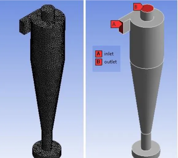
Steady state, turbulent flow inside the cyclone is modelled by means of the commercial CFD solver, ANSYS/Fluent. The pressured-based solver is employed and SIMPLE algorithm is used for the pressure-velocity coupling. Air is chosen as a natural working fluid with the density of 1.225 kg/m3 and the dynamic viscosity of 1.7894e-5 kg/ms. The gravitational acceleration is also set to 9.81 m/s2. The least squares cell-based approach is employed for the gradient discretization. All simulations are considered acceptable when the residuals of all conservation equations are below 10-4. This criterion of convergence is obtained after approximately 1,650 iterations.
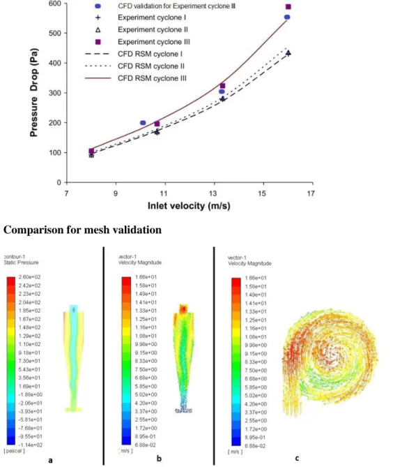
An unstructured mesh is used which is shown in Figure 2 together with the inlet and outlet boundary conditions of the CFD model. For the mesh validation, simulations were performed by taking one of the Xiang's geometries (Cyclone 3). The Reynolds Stress Model as a turbulence modelling was used following Gimbun. For performing a mesh independence test, the gradual improvement of the mesh structure by reducing the size of the finite elements were continued until our results show reasonable agreement with the experimental data of Xiang and the computational data of Gimbun. The final model of the mesh structure has 21905 nodes and 115685 elements. Comparison of the current results with the data of Xiang and Gimbun is presented in Figure 3 for the mesh independence and validation.
Once the validation was achieved, cyclone separators designed via Swift design have been analyzed. Table 1 presents the dimensions of cyclones comparatively.
Figure 3 Comparison for mesh validation
Figure 4a) Pressure contour plot b) Velocity vector plot on the cross-section of the whole domain c) Velocity vector plot on the cross-sectional view from the top
3. Results and Discussions
Figure 4 (a) shows the pressure distribution over the whole domain of the cyclone. It can be seen that the pressure is raised in the vicinity of the walls due to the fact that the high speed jet of air faces an obstacle and thus slows down. Vectors of the velocity magnitude is also shown in Figure 4 (b) for the complete cross-sectional view of the computational domain. This figure reveals that the velocity reaches its maximum values both in the inlet and in the outlet sections. The lowest velocity is observed naturally at the bottom of the cyclone where the flow loses the most of its energy. This is the region where the particles are stored in the system. Additionally, vectors of the velocity are also presented in Figure 4 (c). Clearly, the high-speed flow enters the domain from the inlet and then follows the cylindrical walls forming a vortex shape. The maximum velocity in the system is observed as 16.6 m/s at the vicinity of the inlet and the lowest one is encountered at the bottom of the cyclone as approximately 0.068 m/s where it nearly is a stagnation point, i.e. the momentum of the flow is almost zero in this region, thus the particles inside the flow are collected at the bottom by means of the gravitational force.
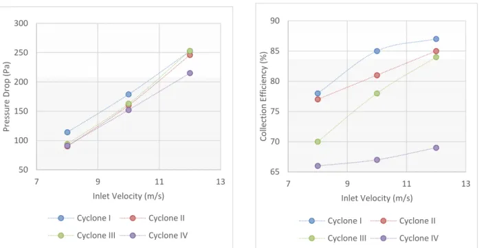
The effect of the inlet velocity on the pressure drop of the cyclone separator is shown in Figure 5 at a constant particle size of 2 µm. Three different inlet velocities have been applied to four different cyclones. Inlet velocities of 8, 10 and 12 m/s have been applied to each separator. It can be clearly seen that there is an increase in the pressure drop as the velocity increases. Higher pressure drops occurred at cyclone I which has the smallest con tip diameter. This result is consistent with the data of Chuah et al. [15].
Figure 6 Collection efficiency at 2µm particle size
Figure 8 Collection efficiency at 4 µm particle size
65 70 75 80 85 90 7 9 11 13 Co lle cti o n E ff ic ie n cy ( % ) Inlet Velocity (m/s) Cyclone I Cyclone II Cyclone III Cyclone IV
76 78 80 82 84 86 88 90 7 9 11 13 Co lle cti o n E ff ic ie n cy ( % ) Inlet Velocity (m/s) Cyclone I Cyclone II Cyclone III Cyclone IV 50 100 150 200 250 300 7 9 11 13 Pre ss u re Dr o p ( Pa ) Inlet Velocity (m/s) Cyclone I Cyclone II Cyclone III Cyclone IV
50 100 150 200 250 300 7 9 11 13 Pre ss u re D ro p (P a) Inlet Velocity (m/s) Cyclone I Cyclone II Cyclone III Cyclone IV
Figure 5 Pressure drop for 2 µm particle size
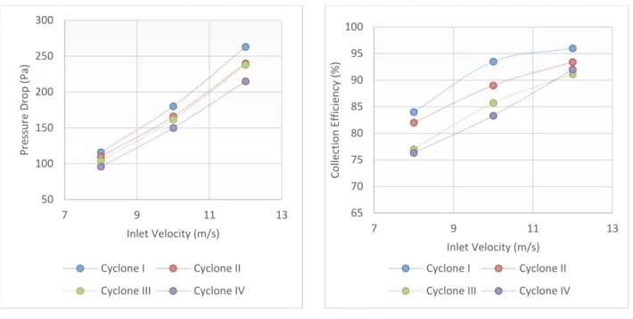
Figure 10 Collection efficiency at 6 µm particle size
In order to see the effects of the cone tip diameter in different particle sizes, four cyclone analyzes were carried out at 8, 10 and 12 m/s velocities. It is understood from Figures 7 and 9 that the particle size does not have a significant effect on the pressure drop. In addition, cone tip diameters also showed similar trends in different particle sizes. Figure 7 and 9 show the pressure drop at 4 µm and 6 µm constant particle sizes, respectively.
Figure 6, 8 and 10, present collection efficiency at different inlet velocities with 2, 4 and 6 µm particle sizes, respectively. With increasing particle size, it is seen that the collection efficiency also increases. When the particle size is 2 µm, the highest efficiency is 87%, while the particle size increases to 4 µm, it can increase to 89.2% and for 6 µm to 96%. Increasing intake speed and increasing the cyclone collection efficiency complies with the literature.
4. Conclusion
The cyclone with four different geometries modeled according to the Swift Design and analysed computationally. It is observed that while high collection efficiencies are obtained in small cone tip diameters, pressure drops are also high. The highest pressure drop and the total collection efficiency occurred at Cyclone I for each geometry. However, no linear connection is found between the cone tip diameter and the pressure drop. Here, it can be seen that it will be advantageous to use cyclone with different cone tip diameters in varying conditions for the optimum operation. The small diameter of the cone tip means having high collection efficiency but does not mean that it provides an optimum working condition. An optimum condition can be achieved in different diameters according to the design and operating conditions of the cyclone separator. It was concluded that the cone tip diameter is effective in determining the optimum working conditions.
65 70 75 80 85 90 95 100 7 9 11 13 Co lle cti o n E ff ic ie n cy ( % ) Inlet Velocity (m/s) Cyclone I Cyclone II Cyclone III Cyclone IV 50 100 150 200 250 300 7 9 11 13 Pre ss u re Dr o p ( Pa ) Inlet Velocity (m/s) Cyclone I Cyclone II Cyclone III Cyclone IV
References
[1] A. Kçpa. (2010). Division of outlet flow in a cyclone vortex finder - The CFD calculations, Sep. Purif. Technol., vol. 75, no. 2, pp. 127–131, 2010, doi: 10.1016/j.seppur.2010.08.009.
[2] P. Silva, C. Briens, and A. Bernis. (2003). Development of a new rapid method to measure erosion rates in laboratory and pilot plant cyclones, Powder Technol. - POWDER TECHNOL, vol. 131, pp. 111–119, Apr. 2003, doi: 10.1016/S0032-5910(02)00338-8.
[3] B. Zhao, H. Shen, and Y. Kang. (2004). Development of a symmetrical spiral inlet to improve cyclone separator performance, Powder Technol., vol. 145, no. 1, pp. 47–50, 2004, doi: 10.1016/j.powtec.2004.06.001.
[4] A. Avci and I. Karagoz. (2003). Effects of flow and geometrical parameters on the collection efficiency in cyclone separators, J. Aerosol Sci., vol. 34, pp. 937–955, Jul. 2003, doi: 10.1016/S0021-8502(03)00054-5.
[5] J. Chen, X. Lu, H. Liu, and C. Yang. (2006). Effect of the bottom-contracted and edge-sloped vent-pipe on the cyclone separator performance, Chem. Eng. J. - CHEM ENG J, vol. 129, pp. 85–90, May 2007, doi: 10.1016/j.cej.2006.11.005.
[6] F. Qian and M. Zhang. (2005). Study of the natural vortex length of a cyclone with response surface methodology, Comput. Chem. Eng., vol. 29, no. 10, pp. 2155–2162, 2005, doi: 10.1016/j.compchemeng.2005.07.011.
[7] B. Wang, D. L. Xu, K. W. Chu, and A. B. Yu. (2006). Numerical study of gas-solid flow in a cyclone separator, Appl. Math. Model., vol. 30, no. 11, pp. 1326–1342, 2006, doi: 10.1016/j.apm.2006.03.011.
[8] M. E. Caliskan, I. Karagoz, A. Avci, and A. Surmen. (2019). Investigation into the effects of various parameters on the performance and classification potential of a cyclone classifier, Powder Technol., vol. 356, pp. 102–111, 2019, doi: 10.1016/j.powtec.2019.07.104.
[9] Y. Zhu and K. W. Lee. (1999). Experimental study on small cyclones operating at high flowrates, J. Aerosol Sci., vol. 30, no. 10, pp. 1303–1315, 1999, doi: 10.1016/S0021-8502(99)00024-5. [10] M. Azadi, M. Azadi, and A. Mohebbi. (2010). A CFD study of the effect of cyclone size on its
performance parameters, J. Hazard. Mater., vol. 182, no. 1–3, pp. 835–841, 2010, doi: 10.1016/j.jhazmat.2010.06.115.
[11] K. W. Chu, B. Wang, D. L. Xu, Y. X. Chen, and A. B. Yu. (2010). CFD-DEM simulation of the gas-solid flow in a cyclone separator, Chem. Eng. Sci., vol. 66, no. 5, pp. 834–847, 2011, doi: 10.1016/j.ces.2010.11.026.
[12] K. Elsayed and C. Lacor. (2011). Numerical modeling of the flow field and performance in cyclones of different cone-tip diameters, Comput. Fluids, vol. 51, no. 1, pp. 48–59, 2011, doi: 10.1016/j.compfluid.2011.07.010.
[13] R. Xiang, S. H. Park, and K. W. Lee. (2001). Effects of cone dimension on cyclone performance, J. Aerosol Sci., vol. 32, pp. 549–561, Apr. 2001, doi: 10.1016/S0021-8502(00)00094-X. [14] I. Karagoz and A. Avci. (2005). Modelling of the Pressure Drop in Tangential Inlet Cyclone
Separators, Aerosol Sci. Technol., vol. 39, no. 9, pp. 857–865, Sep. 2005, doi: 10.1080/02786820500295560.
[15] J. Gimbun, T. G. Chuah, T. S. Y. Choong, and A. Fakhru’l-Razi. (2004). Prediction of the effects of cone tip diameter on the cyclone performance, J. Aerosol Sci., vol. 36, no. 8, pp. 1056–1065, 2005, doi: 10.1016/j.jaerosci.2004.10.014.
![Figure 1The experimental configuration of Xiang [13]](https://thumb-eu.123doks.com/thumbv2/9libnet/4009862.55080/2.892.102.826.730.1092/figure-the-experimental-configuration-of-xiang.webp)