Atomic Layer Deposition of Ruthenium Nanoparticles on
Electrospun Carbon Nano
fibers: A Highly Efficient Nanocatalyst for
the Hydrolytic Dehydrogenation of Methylamine Borane
Mohammad Aref Khalily,
†,§Mehmet Yurderi,
‡Ali Haider,
†Ahmet Bulut,
‡Bhushan Patil,
†Mehmet Zahmakiran,
*
,‡and Tamer Uyar
*
,††Institute of Materials Science and Nanotechnology, National Nanotechnology Research Center (UNAM), Bilkent University,
Ankara 06800, Turkey
‡Department of Chemistry, Science Faculty, Yuzuncu Yıl University, 65080 Van, Turkey
*
S Supporting InformationABSTRACT: We report the fabrication of a novel and highly active nanocatalyst system comprising electrospun carbon nanofiber (CNF)-supported ruthenium nanoparticles (NPs) (Ru@CNF), which can reproducibly be prepared by the ozone-assisted atomic layer deposition (ALD) of Ru NPs on electrospun CNFs. Polyacrylonitrile (PAN) was electropsun into bead-free one-dimensional (1D) nanofibers by electro-spinning. The electrospun PAN nanofibers were converted into well-defined 1D CNFs by a two-step carbonization
process. We took advantage of an ozone-assisted ALD technique to uniformly decorate the CNF support by highly monodisperse Ru NPs of 3.4± 0.4 nm size. The Ru@CNF nanocatalyst system catalyzes the hydrolytic dehydrogenation of methylamine borane (CH3NH2BH3), which has been considered as one of the attractive materials for the efficient chemical hydrogen storage, with a record turnover frequency of 563 mol H2/mol Ru× min and an excellent conversion (>99%) under air
at room temperature with the activation energy (Ea) of 30.1 kJ/mol. Moreover, Ru@CNF demonstrated remarkable reusability performance and conserved 72% of its inherent catalytic activity even at thefifth recycle.
KEYWORDS: atomic layer deposition, ruthenium nanoparticles, carbon nanofibers, electrospinning, catalysis, hydrogen generation, methylamine borane, ammonia borane
■
INTRODUCTIONHeterogeneous catalysis plays a vital role in modern energy and chemical industries.1 Therefore, there has been an immense research endeavor to fabricate supported catalytic nanoparticles (NPs) which are highly active, easily recyclable, simply scalable, reproducible, robust, and straightforwardly prepared. In this context, numerous studies have been conducted for the development of support materials such as metal−organic frameworks,2 zeolites,3 polymers,4 metal oxides,5 and carbon materials,6 and a range of techniques have been employed to decorate metallic NPs on the aforementioned supports.7,8 Particularly, atomic layer deposi-tion (ALD) has become an attractive tool to deposit catalytic metal and metal oxide nanostructures on a variety of supports in recent years.9−13 ALD is a chemical vapor deposition technique, which utilizes gaseous organometallic precursors to produce atomically precise nanostructures andfilms in cyclic manner.14 The self-limiting nature of ALD ensures precisely controlled, uniform, and conformal growth of films and nanostructures on high surface area and porous materials.9,11,14 Electrospinning is a versatile, simple, and cost-effective fabrication technique, which utilizes electrostatic forces to generate one-dimensional (1D) nanofibers from polymer
solutions. Submicron range 1D structuredfibers produced by electrospinning offer a range of advantages such as high surface area to volume ratio, easily tuned mesoporous properties, tunable fiber diameters and surface functionalities, and the capability to control nanofiber composition to get the required properties and function.15 Owing to the versatility of the technique, the electrospun 1D fibers have been found promising in a variety of applications such as catalysis, tissue engineering, water treatment, energy conversion, and stor-age.15−17
Herein, we combined the advantages of two unique fabrication techniques, namely, electrospinning and ALD, to prepare a novel nanocatalyst which is highly active, reusable, nearly nonleaching, and durable. Electrospinning was utilized to synthesize electrospun carbon nanofibers (CNFs) as the support material. Then, nearly monodisperse ruthenium (Ru) NPs (3.4 ± 0.4 nm) were deposited on the as-synthesized CNF support by the ALD technique, which are hereafter referred to as Ru@CNF. The catalytic activity of Ru@CNF Received: March 25, 2018
Accepted: July 10, 2018
Published: July 10, 2018
www.acsami.org Cite This:ACS Appl. Mater. Interfaces 2018, 10, 26162−26169
Downloaded via BILKENT UNIV on February 25, 2019 at 11:29:01 (UTC).
was investigated in the hydrolytic dehydrogenation of methylamine borane (MeAB; CH3NH2BH3) and ammonia
borane (AB; NH3BH3). AB, amine-borane, and their
derivatives such as MeAB have been considered as one of the attractive materials for the efficient chemical hydrogen storage.18,19Particularly, AB and MeAB have recently received great interest because of their 19.6 and 11.1 wt % hydrogen content, respectively.18,19 Moreover, they have considerable advantages: (i) AB and MeAB are highly stable in aqueous solution against self-hydrolysis, (ii) the hydrolytic dehydrogen-ation of AB and MeAB occurs at appreciable rates only in the presence of suitable catalysts, and (iii) the hydrolytic dehydrogenation of AB and MeAB generates 3 mol of H2
per mole of AB and MeAB.18,19 The Ru@CNF nanocatalyst demonstrated excellent catalytic activity in the hydrolytic dehydrogenation of AB and MeAB. A record turnover frequency (TOF) of 1400 mol H2/mol Ru × min for AB
and 563 mol H2/mol Ru × min for MeAB and an excellent conversion (>99%) were achieved under air at room temperature. Moreover, the Ru@CNF nanocatalyst conserved 72% of its inherent catalytic activity even at thefifth recycle for MeAB hydrolysis.
■
EXPERIMENTAL SECTIONChemicals and Materials. Polyacrylonitrile (PAN, Mw ≈ 150 000) was purchased from Scientific Polymer Products, Inc. Methyl-amine hydrochloride (CH3NH2·HCl), dimethylformamide (DMF), tetrahydrofuran (C4H8O), and diethyl ether [(CH3CH2)2O] were purchased from Sigma-Aldrich. All chemicals were used as received and without further purification. MeAB was synthesized according to the literature procedure. The catalytic materials isolated at the end of the synthesis were stored in a Labsconco nitrogen atmosphere glovebox (H2O < 5 ppm, O2< 1 ppm). Deionized water was distilled through the water purification system (Milli-Q water purification system). All glassware and Teflon-coated magnetic stirring bars were washed with acetone and copiously rinsed with distilled water before drying in an oven at 150°C.
Electrospinning. The PAN solution was prepared with 13% (w/v, with respect to solvent) concentration in DMF at 50°C and then cooled down to room temperature. The clear PAN solution was loaded to a 3 mL syringe having a needle of 0.4 mm inner diameter. A 0.5 mL/h flow rate was adjusted by a pump (KD Scientific, KDS 101), and a voltage of 15 kV was applied by high-voltage power supply (Matsusada, AU Series) to initiate electrospinning. The PAN nanofibrous web was collected on an aluminum foil, which was positioned at 10 cm from the end of the tip. The electrospun PAN nanofibers were left in a hood for 72 h to get rid of the residual DMF if any.
Synthesis of Electrospun CNFs. The as-prepared electrospun PAN nanofibrous web was placed on a furnace and heated up to 280 °C at the heating rate of 1 °C/min and held for 1 h under air flow. The sample was allowed to cool down to room temperature, followed by passing argon gas (100 sccm) for 30 min before the carbonization step. The sample was carbonized at 800°C under argon environment with a heating rate of 5°C/min and held for 1.5 h at 800 °C.
Synthesis of Ru@CNF by ALD. Ru NPs were grown on CNFs using a Savannah S100 ALD reactor (Ultratech Inc.). The CNF was dispersed in ethanol and deposited on a clean silicon wafer substrate and was let to dry at room temperature. The sample was loaded to the ALD reaction chamber having a temperature of 290 °C. Bis-(ethylcyclopentadienyl)Ru(II) (Ru(EtCp)2) precursor was preheated to 100°C, and O3was used as the counter reactant. N2was used as the carrier gas with aflow rate of 20 sccm. O3was produced from a pure O2 flow with a Cambridge NanoTech Savannah Ozone Generator. 150 ALD cycles were performed to deposit the Ru NPs on CNF.
Hydrolytic Dehydrogenation of AB and MeAB. The hydro-lytic dehydrogenation of aqueous AB and MeAB solution was surveyed by the volumetric measurement of the rate of hydrogen evolution. The volume of the released gas during the reaction was monitored using a gas burette through water displacement. Prior to starting the reaction, a jacketed one-necked Schlenk tube (20.0 mL), of which the temperature was adjusted by circulating water through the jacket from a constant temperature bath, containing a Teflon-coated stirring bar was placed on a magnetic stirrer. In a typical catalytic activity test, the catalyst was weighed and transferred into the Schlenk tube, to which 8.0 mL of H2O was added, followed by rigorous stirring for 15 min to achieve a thermal equilibrium. Next, 2.0 mL of aqueous AB and MeAB solution (100 mM in 10.0 mL of H2O) was added into the reactionflask via its septum using a 1.0 mL gas-tight syringe, and the catalytic reaction was started (t = 0 min) by stirring the mixture at 900 rpm.
Kinetic Studies for Ru@CNF-Catalyzed Hydrolytic Dehydro-genation of MeAB. To obtain the activation energy (Ea), the hydrolytic dehydrogenation of MeAB ([MeAB] = 100 mM) in the presence of Ru@CNF ([Ru] = 0.01356 mM) was performed at different temperatures (15, 20, 25, and 30 °C) by following the same protocol given above.
Catalytic Stability of Ru@CNF in the Hydrolytic Dehydro-genation of MeAB. The catalytic stability of Ru@CNF in the hydrolytic dehydrogenation of MeAB was assessed via catalytic recyclability experiments. The recyclability of Ru@CNF in the hydrolytic dehydrogenation of MeAB was determined by a series of experiments started with a 10.0 mL aqueous MeAB solution (100 mM in 10.0 mL of H2O) at room temperature. Instantaneously after the achievement of >90% conversion in the first catalytic run, another equivalent amount of fresh MeAB was added to the reaction mixture, leading to further hydrogen evolution.
Environmental Scanning Electron Microscopy. The morphol-ogy of electrospun PAN nanofibers and CNFs was imaged by an FEI Quanta 200 FEG environmental scanning electron microscope with an ETD detector. Electrospun PAN nanofibers were sputter-coated with 5 nm of gold/palladium prior to imaging.
X-ray Photoelectron Spectroscopy. Samples were stabilized on a copper tape and then were analyzed by a Thermo K-alpha monochromatic high-performance X-ray photoelectron spectrometer. Survey and high-resolution X-ray photoelectron spectroscopy (XPS) spectra were recorded with 2 and 50 scans respectively.
Powder X-ray Diffraction. The samples were analyzed by a PANalytical X’Pert powder diffractometer. All data were recorded by using Cu Kα radiation in the range of 2θ = 10°−80°.
Elemental (CHNS−O) Analysis. A total of 2 mg of CNF and 8 mg of vanadium (V) oxide were loaded into a tin container. 2,5-(Bis(5-tert-butyl-2-benzo-oxazol-2-yl))thiophene was used as the standard for calibrations. The measurements were performed by a Thermo Scientific FLASH 2000 series CHNS−O analyzer.
Scanning Transmission Electron Microscopy. An FEI Tecnai G2 F30 transmission electron microscope was used to image the samples. A minute amount of samples wasfirst dispersed in ethanol, followed by dropping 10 μL of the mixture on a carbon-covered copper grid, and the product was let to dry at room temperature.
Inductively Coupled Plasma−Mass Spectroscopy. Ru@CNF (2 mg) was kept in 4 mL of aqua regia for 4 days. Standards of Ru having 500, 250, 125, and 62.5 ppb concentrations were prepared in 2% solution of HNO3/HCl (1:1) for calibration curve. A 2% solution of HNO3/HCl (1:1) was used as the blank. Ru@CNF in aqua regia was passed through a cellulosefilter to get rid of undissolved CNF and then was diluted∼100 times by 2% solution of HNO3/HCl (1:1) for inductively coupled plasma−mass spectroscopy (ICP−MS) analysis. A Thermo X series II inductively coupled plasma−mass spectrometer was used to record the measurements. The ICP−MS operating parameters were as follows: dwell time10 000 ms, channel per mass1, acquisition duration7380, channel spac-ing0.02, and carrier gasargon.
Brunauer−Emmett−Teller Analysis. A small amount of CNF and Ru@CNF (∼50 mg) was weighed into an analysis tube and ACS Applied Materials & Interfaces
degassed under high vacuum at 80°C for 720 min. The analysis was conducted after reweighing the degassed sample. The Brunauer− Emmett−Teller (BET) surface areas were determined from N2 adsorption isotherms by multipoint analysis.
■
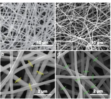
RESULTS AND DISCUSSION1D structured carbon-based nanomaterials have attracted significant attention owing to their superior properties including facile synthesis, large-scale production, low cost, high surface area, excellent mechanical and conductivity properties, high chemical resistance, and structure flexibil-ity.20,21The CNFs to support Ru NPs were synthesized in the following two steps. The PAN viscous solution having 13% (w/v, with respect to solvent) concentration was electrospun to produce well-defined and bead-free PAN nanofibers.22The PAN nanofibers having a diameter in the range of 300−500 nm were imaged by a scanning electron microscope (Figure 1a,b).
The electrospun PAN nanofibers were converted into desired CNFs by a two-step carbonization process.23 First, PAN nanofibers were gradually heated (1 °C/min) up to 280 °C under air to stabilize the nanofibers. This step is called oxidative stabilization, which is crucial for conservation of nanofibrous morphology. The next step was to carbonize the stabilized PAN nanofibers at 800 °C under inert argon atmosphere to get well-defined CNFs (Figure 1c,d). Owing to
loss of hydrogen and nitrogen atoms during stabilization and carbonization steps, we observed the shrinkage in diameters of CNFs to 200−350 nm (Figure 1d).
To investigate the chemical composition of the produced CNF, we conducted XPS and CHNS−O elemental analysis. The survey spectrum shown inFigure 2a reveals the presence of three peaks at 284, 400, and 532 eV, which corresponds to carbon (C), nitrogen (N), and oxygen (O) species, respectively. When these three peaks were quantified, the CNF consisted of 82.82% C, 13.33% N, and 3.05% O. We further analyzed CNF by elemental analysis showing the presence of 1.13% hydrogen (H) atom and 14.4% N. Highly reactive radicals form during the course of carbonization at 800 °C. These radicals react with water vapor or oxygen as soon as CNFs are exposed to air forming hydroxyl groups. The presence of trace amount of H and O atoms could be due to the formation of hydroxyl groups on CNF.24It is well-known that not only the extent of N-doping of support materials but also the chemical environment of N has a significant effect on catalytic reactions. Therefore, we conducted high-resolution XPS of N 1s to acquire qualitative and quantitative information regarding N species present in the chemical structure of CNF. The deconvoluted N 1s spectra of CNF point out the presence of different nitrogen species such as pyridinic (397.9 eV), nitrile (399.6 eV), and quaternary (400.9 eV) nitrogen (Figure 2b).24The powder X-ray diffraction (PXRD) pattern of CNF displays the typical characteristic of turbostratic carbon (Figure 2c), which is similar to that of the graphitic structure with a huge interlayer distance between the graphene sheets (002 planes).24
Synthesis of highly monodisperse metallic NPs with a uniform coating of support material is extremely essential to obtain accurate details regarding the catalytic performance of the catalyst system. To this end, we employed the thermal ALD technique to decorate CNFs with Ru NPs. To date, several ALD processes are investigated for Ru growth using different metal−organic precursors along with oxygen, oxygen plasma, and ammonia plasma as reactant gases.25−27Ru growth with aforementioned reactant gases usually suffer from nucleation delays, high surface roughness, and low growth rate.28It was shown that ozone (O3) as the reactant gas can be used for the smooth growth of Ru.28
Ru(EtCp)2was used as the Ru precursor, and O3was used
as the reactant gas. Ru(EtCp)2 was preheated to 100 °C to
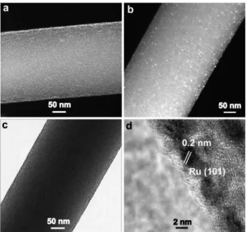
generate a gaseous precursor, and the ALD reaction chamber was kept at 290°C during deposition. After 150 cycles of Ru deposition on CNF, we observed the growth of well-dispersed and highly monodisperse Ru NPs (Figure 3a,b) on CNF (Ru@ CNF) as imaged by high-angle annular dark field−scanning
Figure 1.Representative SEM images of electrospun PAN nanofibers (a,b) and CNF produced at 800°C (c,d).
Figure 2.Survey XPS spectrum of CNF (a) and high-resolution N 1s XPS spectrum of CNF in the range of 403−395 eV (b). PXRD pattern of CNF in the range of 2θ = 10−80° (c).
transmission electron microscopy (HAADF−STEM). The bright-field TEM (BFTEM) image (Figure 3c) further confirmed uniform decoration of Ru NPs on CNF. The STEM−energy-dispersive X-ray spectroscopy (EDXS) analysis of Ru@CNF clearly shows the existence of Ru species on CNF (Figure S1). The high-resolution TEM (HRTEM) image (Figure 3d) of Ru@CNF shows the crystal plane of Ru(101), and the corresponding plane spacing was measured to be 0.2 nm.28,29 This result is in good agreement with the value acquired by PXRD of Ru@CNF (Figure 4a).28
To further investigate the oxidation state of Ru species, we conducted high-resolution XPS for Ru@CNF. Because the
binding energy of Ru 3d overlaps (Figure S2) with C 1s (284 eV), therefore, we analyzed the Ru 3p3/2region (458−468 eV).
The deconvolution of Ru 3p XPS spectrum (Figure 4b) of Ru@CNF reveals the coexistence of two peaks at 461.89 and 465.13 eV, which can be attributed to metallic Ru and RuO2 phase, respectively.30Formation of RuO2species may originate
from the surface oxidation of Ru(0) NPs during the XPS sampling procedure31 and/or during Ru growth in the ALD chamber. Note that the percentage of metallic Ru (85.3%) dominates RuO2 species (14.7%) and N-doped CNF aids to
keep Ru at its reduced state.
To gain more insights into how uniformly the Ru NPs are deposited on the surface of CNF, we conducted elemental mapping for Ru@CNF from a large area of the sample. The SEM images of Ru@CNF with elemental mapping for C, N, O, and Ru depicted in Figure 5a−e indicate that (i) there is a
highly uniform distribution of Ru in Ru@CNF and (ii) there exists no bulk Ru outside of Ru@CNF. A size distribution graph (Figure 5f) was constructed from the STEM images (Figure S3) by randomly counting∼100 Ru NPs using ImageJ software to assess the size and monodispersity of Ru NPs produced by ALD. The Ru NPs have an average size of 3.4± 0.4 nm. We further conducted BET analysis to estimate the surface areas of CNF and Ru@CNF materials (Figures S4 and S5). The surface areas of 63.4 g/m2for CNF and 24.5 g/m2for
Ru@CNF were determined from N2adsorption isotherms by
multipoint analysis. Finally, we performed ICP−MS to calculate the percentage loading of Ru. The digested Ru@ CNF in aqua regia measured by ICP−MS revealed 0.4% Ru loading on CNF.
The catalytic activity of Ru@CNF was examined in the hydrolytic dehydrogenation of MeAB by measuring the volume
Figure 3. HAADF−STEM (a,b), BFTEM (c), and HRTEM (d) images of Ru@CNF.
Figure 4.PXRD pattern of Ru@CNF in the range of 2θ = 10−80° (a) and high-resolution Ru 3p XPS spectrum of Ru@CNF (b).
Figure 5. SEM image of Ru@CNF (a) and SEM images with elemental mapping of C (b), N (c), O (d), and Ru (e). Particle size histogram of Ru NPs in Ru@CNF obtained from STEM imaging (f). ACS Applied Materials & Interfaces
of hydrogen gas generated during the reaction (Scheme 1) and by 11B-{1H}-NMR spectroscopy to identify the reaction
products. Among the materials for hydrogen storage,32−35 AB, amine-borane, and its derivatives such as MeAB have been considered as one of the attractive materials for the efficient chemical hydrogen storage.18,19Up to date, the catalysts tested in the hydrolytic dehydrogenation of MeAB are graphene-supported core@shell-type Ag@M (M = Co, Ni, and Fe) NPs,19 Cu@Co NPs,36 Ag@CoNi NPs,37 Ru@Co NPs,38 Ru@Ni NPs,39and MCM-41-encapsulated Ru NPs.40Among these catalytic architectures, Ru-based systems provide high activities in the hydrolytic dehydrogenation of MeAB.
Before testing the catalytic activity of Ru@CNF, the catalytic reactivity of the pristine CNF host material was examined under the same conditions (vide infra). The result of this experiment showed that the CNF host material is catalytically inactive in the hydrolytic dehydrogenation of MeAB. Then, Ru@CNF-catalyzed hydrolytic dehydrogenation of MeAB was performed at various temperatures (15, 20, 25, and 30°C). The plot of mole of evolved H2per mole of MeAB versus the
time graph for Ru@CNF-catalyzed hydrolytic dehydrogen-ation of MeAB at various temperatures is given inFigure 6a. As expected, the rate of hydrogen generation is enhanced by the increase of the reaction temperature, and Ru@CNF can catalyze the hydrolytic dehydrogenation of MeAB at complete conversion under air at temperatures ≥25 °C. Moreover, we observed that at low temperatures (20 and 15°C), Ru@CNF cannot provide the complete conversion of MeAB. The same problem has already been reported for other catalytic systems tested in the hydrolytic dehydrogenation of MeAB.36,37 The most plausible reason of this situation is the inefficient activation of B−N bond on the Ru NP surface at low temperatures.41
The initial TOF values were determined to be 120, 337, 563, and 1500 mol H2/mol Ru × min at 15, 20, 25, and 30 °C, respectively. To the best of our knowledge, the initial TOF value obtained by Ru@CNF for the room-temperature hydrolytic dehydrogenation of MeAB (563 mol H2/mol Ru
× min) at complete conversion is the highest catalytic activity value recorded for this catalytic transformation (Table 1). The observed rate constants were found to be kobs = 0.00163, 0.0458, 0.0763, and 0.0.2033 mol H2/(mol MeAB× min.) at
15, 20, 25, and 30 °C, respectively. These observed rate constants (kobs) were used to construct the Arrhenius plot
(Figure S6). From the slope of the Arrhenius plot, the activation energy (Ea) for the Ru@CNF-catalyzed
dehydrogen-ation of MeAB was found to be 30.1 kJ/mol. This value is lower than those obtained by [email protected]/reduced graphene
oxide (r-GO) (55.9 kJ/mol),36 Ru@Ni/r-GO (37 kJ/mol),39 and Ru/MCM-41 (47.6 kJ/mol)40 catalysts in the hydrolytic dehydrogenation of MeAB. In addition to the volumetric measurement of the hydrogen gas generated from the Ru@ CNF-catalyzed hydrolytic dehydrogenation of MeAB, the conversion of MeAB to methylammonium metaborate (Scheme 1) was also examined by comparing the signal intensities of MeAB and metaborate anion atδ = −18.4 and Scheme 1. Transition-Metal-Catalyzed Hydrolytic
Dehydrogenation of MeAB
Figure 6.(a) Plot of mole of evolved H2per mole of MeAB vs the time graph for the hydrolytic dehydrogenation of MeAB ([MeAB] = 100 mM in 10.0 mL of H2O) catalyzed by Ru@CNF (in all [Ru] = 0.0135 mM) at different temperatures and (b) plot of mole of evolved H2per mole of MeAB vs the time graph for thefirst−fifth recycle in the Ru@CNF ([Ru] = 0.0135 mM)-catalyzed hydrolytic dehydrogen-ation of MeAB ([MeAB] = 100 mM in 10.0 mL H2O) at room temperature.
Table 1. Comparison of the Catalytic Performance of the Ru@CNF Catalyst with the Prior Heterogeneous Catalyst Systems Reported for the Hydrolytic Dehydrogenation of MeAB
catalyst temp. (°C) conv. (%) activitya references
Ag@Co/graphene 298 99 1.2 19 Ag@Ni/graphene 298 80 0.6 19 Cu@Co/r-GO 293 90 2.3 36 Ag@CoNi/r-GO 298 89 3.5 37 RuCo/graphene 298 97 450 38 RuNi/graphene 298 51 231 39 Ru/MCM-41 298 28 131 40
Ru@CNF 298 99 563 this study
aInitial TOF values (TOF = mol H
2/mol catalyst × time (min)) calculated at∼20% of conversion achieved.
13.4 ppm, respectively, in the 11B-{1H}-NMR spectra of the
solution (Figure S7).19,36−38
Although we did not perform the experiments to investigate the mechanistic insights for the Ru@CNF-catalyzed hydrolysis of MeAB, we believe that the Ru@CNF-catalyzed hydrolysis of MeAB proceeds through the same mechanism with metal-catalyzed hydrolysis of AB (NH3BH3) as pointed out by Xu and Chandra.42It involves the interaction of MeAB with the surface of Ru NPs to form an active complex at the transition state. The active complex is then attacked by water molecules that lead to the dissociation of B−N bonds to produce borate anion and methylammonium cation along with H2release.
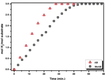
We also performed a control experiment in which the catalytic reactivity of Ru@CNF was investigated in the catalytic hydrolysis of AB under identical conditions with those of MeAB (Figure 7). As shown inFigure 7,
Ru@CNF-catalyzed hydrolytic dehydrogenation of AB proceeds faster than that of MeAB, which can be explained by the higher reducing reactivity of AB with respect to that of MeAB.43The initial TOF value of Ru@CNF in the hydrolytic dehydrogen-ation of AB was found to be 1400 mol H2/mol Ru × min,
which is almost 2.5 times higher than that obtained with Ru@ CNF in the hydrolytic dehydrogenation of MeAB. Moreover, this value is higher than that obtained by the Ru@r-GO catalyst (TOF = 600 mol H2/mol Ru× min), which had been
known as the most active heterogeneous catalyst for the hydrolysis of AB.44
Additionally, we examined the catalytic performance of precatalyst RuCl3 to catalyze the hydrolytic dehydrogenation
of MeAB under identical conditions with those of Ru@CNF (Figure S8). The initial TOF value of RuCl3(TOF = 2250 mol
H2/mol Ru × min) is almost 4.0 times higher than that of Ru@CNF, but the sole stabilizer present in the system is the weakly coordinating chloride anion, which cannot provide enough stabilization for the resulting Ru NPs. For this reason, these Ru NPs have lost their activity at 53% conversion because of the aggregation of Ru NPs into the bulk Ru, which was seen by the naked eye in the solution.
The catalytic stability of Ru@CNF was investigated by testing the recyclability performance of Ru@CNF in the hydrolytic dehydrogenation of MeAB. In the recyclability
experiments, fresh aqueous MeAB was added into the reaction solution when all MeAB from the previous run was converted to H2 and CH3NH2BO2, and by this way, the reaction was continued up tofive consecutive cycles. As given inFigure 6b, the Ru@CNF nanocatalyst provides complete conversion of MeAB dehydrogenation by retaining 72% of its inherent catalytic activity even at thefifth recycle. The morphological investigation of the recovered catalyst from the fifth recycle
was performed by SEM and STEM analyses. The fiber
morphology was still preserved for Ru@CNF (Figure S9), and inspection of STEM image (Figure S10) of the recovered Ru@ CNF catalyst revealed slender clumping Ru NPs supported on CNF, which explains the observed slight decrease in the catalytic activity at thefifth recycle. The leaching possibility of Ru NPs from CNF to reaction solution throughout the recyclability experiments was also investigated by performing ICP−MS analyses on aliquots of the reaction solutions taken at the end of first, third, and fifth recycles, in which no Ru was detected, confirming the retention of Ru NPs on the CNF framework. The existence of N-containing groups on the surface of CNF helps in the stabilization of CNF-supported Ru NPs against agglomeration and sintering. It is well-known that N-containing ligands in both colloidal form45,46 and surface-impregnated form47act as a good stabilizer for the metal NPs. We also investigated the XRD and XPS analyses of the recovered catalyst from thefifth recycle (Figure S11). A slight broadening of the Ru signals in the XRD spectrum is observed when compared to that of fresh Ru@CNF catalyst. Meanwhile, the XPS analysis of the recovered Ru@CNF catalyst reveals the presence of 83.8% metallic Ru, which is almost the same with fresh Ru@CNF catalyst consisted of 85.3% metallic Ru. Taking all the results together, it is concluded that Ru@CNF acts as a highly durable nanocatalyst against leaching, sintering, and clumping, which makes it a highly efficient and recyclable heterogeneous catalyst for the hydrolytic dehydrogenation of MeAB and AB.
■
CONCLUSIONSIn summary, we combined the advantages of electrospinning and ALD techniques to fabricate a highly active and reusable nanocatalyst system. Well-defined 1D CNFs were produced from electrospun PAN nanofibers. The resulting CNFs were uniformly decorated by highly monodisperse Ru NPs of 3.4± 0.4 nm size using the ALD technique. Ru@CNF has reproducibly been synthesized and characterized by the combination of multipronged techniques. The resulting Ru@ CNF nanocatalyst revealed a record activity (563 mol H2/mol
Ru × min), excellent conversion (>99%), and remarkable reusability performance for the room-temperature hydrolytic dehydrogenation of MeAB under air. Ru@CNF was shown to be nearly nonleaching and conserved 72% of its inherent catalytic activity even at thefifth recycle. Likewise, Ru@CNF catalyzed the hydrolysis of AB to generate 3 mol of H2, with a
remarkable TOF of 1400 mol H2/mol Ru × min at room
temperature. This uniquely active and stable catalytic material has strong potential to be exploited in practical applications, where AB and MeAB are utilized as a viable hydrogen carrier in mobile fuel cell applications.
■
ASSOCIATED CONTENT*
S Supporting InformationThe Supporting Information is available free of charge on the ACS Publications websiteat DOI:10.1021/acsami.8b04822.
Figure 7.Plot of mole of evolved H2per mole of AB and H2per mole of MeAB vs the time graph for the hydrolytic dehydrogenation of AB and MeAB catalyzed by Ru@CNF at room temperature.
HAADF−STEM image and STEM−EDXS spectrum of Ru@CNF; survey XPS spectrum of Ru@CNF;
HAADF−STEM images of Ru@CNF; BET of CNF
and Ru@CNF; Arrhenius plot for the Ru@CNF-catalyzed hydrolytic dehydrogenation of MeAB; 11
B-[1H]-NMR spectra of aqueous MeAB solution (fresh) and reaction solution at the end of the Ru@CNF-catalyzed hydrolytic dehydrogenation of MeAB; plots of mole of evolved H2per mole of MeAB versus the time
graph for the hydrolytic dehydrogenation of MeAB in the presence of RuCl3·3H2O and Ru@CNF; SEM image
of Ru@CNF harvested from thefifth catalytic recycle in the hydrolytic dehydrogenation of MeAB; HAADF−
STEM image and STEM−EDXS spectrum of Ru@CNF
harvested from thefifth catalytic recycle in the hydrolytic dehydrogenation of MeAB; and XRD and XPS analyses of recovered Ru@CNF after the fifth catalytic cycle (PDF)
■
AUTHOR INFORMATIONCorresponding Authors
*E-mail:[email protected](M.Z.). *E-mail:[email protected] (T.U.).
ORCID
Mehmet Zahmakiran:0000-0002-5633-3811
Tamer Uyar:0000-0002-3989-4481
Present Address
§Laboratory for Biomolecular Nanotechnology, MESA +
Institute for Nanotechnology, University of Twente, Enschede, Netherlands.
Author Contributions
M.A.K. has conducted the electrospinning, carbonization, and ALD experiments and synthesis and characterization of CNF and Ru@CNF; A.H. has performed the initial ALD of Ru and ALD optimization studies; B.P. has contributed the repro-duction of Ru@CNF and performed related characterization during the revision stage of the manuscript; M.Y., A.B., and M.Z. have performed all the catalysis experiments; and M.A.K., M.Z., and T.U. have contributed to the writing of the manuscript. All authors have given approval to thefinal version of the manuscript.
Funding
The Scientific and Technological Research Council of Turkey (TUBITAK, project no. 115Z488) is acknowledged for funding this research. M.Z. thanks the Research Fund of Van Yüzüncü Yıl University Office of Scientific Research Project (FOA-2016-5376).
Notes
The authors declare no competingfinancial interest.
■
ACKNOWLEDGMENTSThe authors thank Prof. Necmi Biyikli for the ALD approach and Hamit Eren for the initial ALD experiments; the authors also thank Dr. Amaresh C. Pradhan for obtaining the data of STEM, EDXS, and SEM for the reused Ru@CNF sample. Dr. Bekir Satilmis and Dr. Fuat Topuz are acknowledged for BET measurements.
■
REFERENCES(1) Munnik, P.; de Jongh, P. E.; de Jong, K. P. Recent Developments in the Synthesis of Supported Catalysts. Chem. Rev. 2015, 115, 6687− 6718.
(2) Zhu, L.; Liu, X.-Q.; Jiang, H.-L.; Sun, L.-B. Metal-Organic Frameworks for Heterogeneous Basic Catalysis. Chem. Rev. 2017, 117, 8129−8176.
(3) Ennaert, T.; Van Aelst, J.; Dijkmans, J.; De Clercq, R.; Schutyser, W.; Dusselier, M.; Verboekend, D.; Sels, B. F. Potential and challenges of zeolite chemistry in the catalytic conversion of biomass. Chem. Soc. Rev. 2016, 45, 584−611.
(4) Kaushik, M.; Moores, A. Review: nanocelluloses as versatile supports for metal nanoparticles and their applications in catalysis. Green Chem. 2016, 18, 622−637.
(5) Campbell, C. T. The Energetics of Supported Metal Nano-particles: Relationships to Sintering Rates and Catalytic Activity. Acc. Chem. Res. 2013, 46, 1712−1719.
(6) Pérez-Mayoral, E.; Calvino-Casilda, V.; Soriano, E. Metal-supported carbon-based materials: opportunities and challenges in the synthesis of valuable products. Catal. Sci. Technol. 2016, 6, 1265− 1291.
(7) Serp, P.; Kalck, P.; Feurer, R. Chemical vapor deposition methods for the controlled preparation of supported catalytic materials. Chem. Rev. 2002, 102, 3085−3128.
(8) Schwarz, J. A.; Contescu, C.; Contescu, A. Methods for Preparation of Catalytic Materials. Chem. Rev. 1995, 95, 477−510.
(9) O’Neill, B. J.; Jackson, D. H. K.; Lee, J.; Canlas, C.; Stair, P. C.; Marshall, C. L.; Elam, J. W.; Kuech, T. F.; Dumesic, J. A.; Huber, G. W. Catalyst Design with Atomic Layer Deposition. ACS Catal. 2015, 5, 1804−1825.
(10) Celebioglu, A.; Ranjith, K. S.; Eren, H.; Biyikli, N.; Uyar, T. Surface Decoration of Pt Nanoparticles via ALD with TiO2 Protective Layer on Polymeric Nanofibers as Flexible and Reusable Heteroge-neous Nanocatalysts. Sci. Rep. 2017, 7, 13401.
(11) Khalily, M. A.; Eren, H.; Akbayrak, S.; Susapto, H. H.; Biyikli, N.; Özkar, S.; Guler, M. O. Facile Synthesis of Three-Dimensional Pt-TiO2 Nano-networks: A Highly Active Catalyst for the Hydrolytic Dehydrogenation of Ammonia-Borane. Angew. Chem., Int. Ed. 2016, 55, 12257−12261.
(12) Lu, J.; Elam, J. W.; Stair, P. C. Synthesis and Stabilization of Supported Metal Catalysts by Atomic Layer Deposition. Acc. Chem. Res. 2013, 46, 1806−1815.
(13) Ranjith, K. S.; Celebioglu, A.; Eren, H.; Biyikli, N.; Uyar, T. Monodispersed, Highly Interactive Facet (111)-Oriented Pd Nano-grains by ALD onto Free-Standing and Flexible Electrospun Polymeric Nanofibrous Webs for Catalytic Application. Adv. Mater. Interfaces 2017, 4, 1700640.
(14) Hämäläinen, J.; Ritala, M.; Leskelä, M. Atomic Layer Deposition of Noble Metals and Their Oxides. Chem. Mater. 2014, 26, 786−801.
(15) Peng, S.; Jin, G.; Li, L.; Li, K.; Srinivasan, M.; Ramakrishna, S.; Chen, J. Multi-functional electrospun nanofibres for advances in tissue regeneration, energy conversion & storage, and water treatment. Chem. Soc. Rev. 2016, 45, 1225−1241.
(16) Ranjith, K. S.; Uyar, T. Rational synthesis of Na and S co-catalyst TiO2-based nanofibers: presence of surface-layered TiS3 shell grains and sulfur-induced defects for efficient visible-light driven photocatalysis. J. Mater. Chem. A 2017, 5, 14206−14219.
(17) Pradhan, A. C.; Uyar, T. Morphological Control of Mesoporosity and Nanoparticles within Co3O4-CuO Electrospun Nanofibers: Quantum Confinement and Visible Light Photocatalysis Performance. ACS Appl. Mater. Interfaces 2017, 9, 35757−35774.
(18) Rossin, A.; Peruzzini, M. Ammonia-Borane and Amine-Borane Dehydrogenation Mediated by Complex Metal Hydrides. Chem. Rev. 2016, 116, 8848−8872.
(19) Yang, L.; Luo, W.; Cheng, G. Graphene-Supported Ag-Based Core-Shell Nanoparticles for Hydrogen Generation in Hydrolysis of Ammonia Borane and Methylamine Borane. ACS Appl. Mater. Interfaces 2013, 5, 8231−8240.
(20) Zhu, J.; Holmen, A.; Chen, D. Carbon Nanomaterials in Catalysis: Proton Affinity, Chemical and Electronic Properties, and their Catalytic Consequences. ChemCatChem 2013, 5, 378−401.
(21) De Jong, K. P.; Geus, J. W. Carbon nanofibers: Catalytic synthesis and applications. Catal. Rev. 2000, 42, 481−510.
(22) Kayaci, F.; Vempati, S.; Ozgit-Akgun, C.; Biyikli, N.; Uyar, T. Enhanced photocatalytic activity of homoassembled ZnO nanostruc-tures on electrospun polymeric nanofibers: A combination of atomic layer deposition and hydrothermal growth. Appl. Catal., B 2014, 156− 157, 173−183.
(23) Inagaki, M.; Yang, Y.; Kang, F. Carbon nanofibers prepared via electrospinning. Adv. Mater. 2012, 24, 2547−2566.
(24) Yang, D.-S.; Chaudhari, S.; Rajesh, K. P.; Yu, J.-S. Preparation of Nitrogen-Doped Porous Carbon Nanofibers and the Effect of Porosity, Electrical Conductivity, and Nitrogen Content on Their Oxygen Reduction Performance. ChemCatChem 2014, 6, 1236−1244. (25) Lu, J.; Low, K.-B.; Lei, Y.; Libera, J. A.; Nicholls, A.; Stair, P. C.; Elam, J. W. Toward atomically-precise synthesis of supported bimetallic nanoparticles using atomic layer deposition. Nat. Commun. 2014, 5, 3264.
(26) Maikap, S.; Wang, T. Y.; Tzeng, P. J.; Lin, C. H.; Lee, L. S.; Yang, J. R.; Tsai, M. J. Charge storage characteristics of atomic layer deposited RuOx nanocrystals. Appl. Phys. Lett. 2007, 90, 253108.
(27) Profijt, H. B.; Potts, S. E.; van de Sanden, M. C. M.; Kessels, W. M. M. Plasma-Assisted Atomic Layer Deposition: Basics, Oppor-tunities, and Challenges. J. Vac. Sci. Technol., A 2011, 29, 050801.
(28) Kim, J.-Y.; Kil, D.-S.; Kim, J.-H.; Kwon, S.-H.; Ahn, J.-H.; Roh, J.-S.; Park, S.-K. Ru Films from Bis(ethylcyclopentadienyl)ruthenium Using Ozone as a Reactant by Atomic Layer Deposition for Capacitor Electrodes. J. Electrochem. Soc. 2012, 159, H560−H564.
(29) Cui, X.; Surkus, A.-E.; Junge, K.; Topf, C.; Radnik, J.; Kreyenschulte, C.; Beller, M. Highly selective hydrogenation of arenes using nanostructured ruthenium catalysts modified with a carbon-nitrogen matrix. Nat. Commun. 2016, 7, 11326.
(30) Armenise, S.; Roldán, L.; Marco, Y.; Monzón, A.; García-Bordejé, E. Elucidation of Catalyst Support Effect for NH3 Decomposition Using Ru Nanoparticles on Nitrogen-Functionalized Carbon Nanofiber Monoliths. J. Phys. Chem. C 2012, 116, 26385− 26395.
(31) Zahmakıran, M.; Özkar, S. Zeolite confined nanostructured dinuclear ruthenium clusters: preparation, characterization and catalytic properties in the aerobic oxidation of alcohols under mild conditions. J. Mater. Chem. 2009, 19, 7112−7118.
(32) Chen, S.; Takata, T.; Domen, K. Particulate photocatalysts for overall water splitting. Nat. Rev. Mater. 2017, 2, 17050.
(33) Yan, J.-M.; Wang, Z.-L.; Gu, L.; Li, S.-J.; Wang, H.-L.; Zheng, W.-T.; Jiang, Q. AuPd-MnOx/MOF-Graphene: An Efficient Catalyst for Hydrogen Production from Formic Acid at Room Temperature. Adv. Energy Mater. 2015, 5, 1500107.
(34) Li, S.-j.; Ping, Y.; Yan, J.-M.; Wang, H.-L.; Wu, M.; Jiang, Q. Facile synthesis of AgAuPd/graphene with high performance for hydrogen generation from formic acid. J. Mater. Chem. A 2015, 3, 14535−14538.
(35) Jena, P. Materials for Hydrogen Storage: Past, Present, and Future. J. Phys. Chem. Lett. 2011, 2, 206−211.
(36) Du, Y.; Cao, N.; Yang, L.; Luo, W.; Cheng, G. One-step synthesis of magnetically recyclable rGO supported Cu@Co core-shell nanoparticles: highly efficient catalysts for hydrolytic dehydro-genation of ammonia borane and methylamine borane. New J. Chem. 2013, 37, 3035−3042.
(37) Yang, L.; Su, J.; Meng, X.; Luo, W.; Cheng, G. In situ synthesis of graphene supported Ag@CoNi core-shell nanoparticles as highly efficient catalysts for hydrogen generation from hydrolysis of ammonia borane and methylamine borane. J. Mater. Chem. A 2013, 1, 10016−10023.
(38) Cao, N.; Su, J.; Luo, W.; Cheng, G. Graphene supported Ru@ Co core-shell nanoparticles as efficient catalysts for hydrogen generation from hydrolysis of ammonia borane and methylamine borane. Catal. Commun. 2014, 43, 47−51.
(39) Cao, N.; Su, J.; Luo, W.; Cheng, G. Hydrolytic dehydrogen-ation of ammonia borane and methylamine borane catalyzed by graphene supported Ru@Ni core-shell nanoparticles. Int. J. Hydrogen Energy 2014, 39, 426−435.
(40) Wen, L.; Zheng, Z.; Luo, W.; Cai, P.; Cheng, G.-Z. Ruthenium deposited on MCM-41 as efficient catalyst for hydrolytic dehydrogen-ation of ammonia borane and methylamine borane. Chin. Chem. Lett. 2015, 26, 1345−1350.
(41) Wang, C.; Tuninetti, J.; Wang, Z.; Zhang, C.; Ciganda, R.; Salmon, L.; Moya, S.; Ruiz, J.; Astruc, D. Hydrolysis of Ammonia-Borane over Ni/ZIF-8 Nanocatalyst: High Efficiency, Mechanism, and Controlled Hydrogen Release. J. Am. Chem. Soc. 2017, 139, 11610−11615.
(42) Xu, Q.; Chandra, M. Catalytic activities of non-noble metals for hydrogen generation from aqueous ammonia-borane at room temperature. J. Power Sources 2006, 163, 364−370.
(43) Staubitz, A.; Robertson, A. P. M.; Sloan, M. E.; Manners, I. Amine− and Phosphine−Borane Adducts: New Interest in Old Molecules. Chem. Rev. 2010, 110, 4023−4078.
(44) Du, C.; Ao, Q.; Cao, N.; Yang, L.; Luo, W.; Cheng, G. Facile synthesis of monodisperse ruthenium nanoparticles supported on graphene for hydrogen generation from hydrolysis of ammonia borane. Int. J. Hydrogen Energy 2015, 40, 6180−6187.
(45) Yurderi, M.; Bulut, A.; Caner, N.; Celebi, M.; Kaya, M.; Zahmakiran, M. Amine grafted silica supported CrAuPd alloy nanoparticles: superb heterogeneous catalysts for the room temper-ature dehydrogenation of formic acid. Chem. Commun. 2015, 51, 11417−11420.
(46) Zahmakıran, M.; Tristany, M.; Philippot, K.; Fajerwerg, K.; Özkar, S.; Chaudret, B. Aminopropyltriethoxysilane stabilized ruthenium(0) nanoclusters as an isolable and reusable heterogeneous catalyst for the dehydrogenation of dimethylamine-borane. Chem. Commun. 2010, 46, 2938−2940.
(47) Bulut, A.; Yurderi, M.; Karatas, Y.; Say, Z.; Kivrak, H.; Kaya, M.; Gulcan, M.; Ozensoy, E.; Zahmakiran, M. MnOx-Promoted PdAg Alloy Nanoparticles for the Additive-Free Dehydrogenation of Formic Acid at Room Temperature. ACS Catal. 2015, 5, 6099−6110. ACS Applied Materials & Interfaces
![Figure 6. (a) Plot of mole of evolved H 2 per mole of MeAB vs the time graph for the hydrolytic dehydrogenation of MeAB ([MeAB] = 100 mM in 10.0 mL of H 2 O) catalyzed by Ru@CNF (in all [Ru] = 0.0135 mM) at different temperatures and (b) plot of mole of evo](https://thumb-eu.123doks.com/thumbv2/9libnet/5605881.110592/5.938.483.848.98.689/figure-evolved-hydrolytic-dehydrogenation-meab-catalyzed-different-temperatures.webp)