MMcdT*04
10’” Int. Conf. on Mathematical Methods In Electmmagnetlc Theory<,&
Sept. 14-17, 2004. Dniepmpetrovsk, UkralneANALYSIS OF THE 2D NONCONCENTRIC LARGE REFLECTOR
ANTENNA-IN-RADOME SYSTEM: H-POLARIZATION CASE
Taner
Oguzer
Bilkent University, Electrical and Electronics Eng. Dept., Computational Electromagnetics Lab. Bilkent Ankara, TURKEY
[email protected]
Abstract - 2D nonconcentric reflector antenna-in-radome system is analyzed for H-polarization case. Rigorous formulation is performed depending on the MOR, Green’s function and CSP methods. Larger geometries are solved in reasonable cpu times by using the FFT based algorithm in the computation of the Green’s function.
1. INTRODUCTION
The radome is coverage of the reflector antenna system, hut it makes an effect on the radiation characteristics. Therefore it is necessary to have accurate simulation tools for the engineering design purposes.
The older ray tracing techniques were extended by considering the all hybrid ray combinations during the transmission through the radome [2]. Radome problems can also be solved by using numerical methods like the MOM or the FEM technique for the electrically small and medium size geometries.
The circularly cylindrical reflector antenna and the covering concentric circular radome was a problem
of
interest and it was analyzed in [4] for both polarization cases. The nonconcentric circular radome covering the circularly cylindrical reflector antenna system is another problem of interest and it was solved in [ 5 ] again by combining MOR, Green’s function technique and CSP method. Furthermore in this study an optimization is performed depending on the problem parameters.
The present study can be considered as the different computational way of the previous work performed in [ 5 ] . In that study it was noted that a special care should be taken in the numerical evaluation of the successive summations. These summations come from the geometrical transformations of the cylindrical wave functions by the well-@own addition theorem. However here due to the periodic nature of the problem one can expand green’s function into the Fourier series on the radome centered coordinate system. Then the scattered part
of
the green’s function can be easily computed in the other reflector centered coordinate system by using the available FFT algorithm. The FFT algorithm based formulations of the electromagnetic scattering problems were also used in literature related with the MOR techniques. This way of computation provide QS to solve the larger problems in the more reasonable CPU time durations and no further efforts are spent on the convergence of the successive series.11. FORMULATION
Fig. 1. Geometry of the problem
Geomehy of the reflector antenna and its covering radome system is given in Figure 1. Here there is a 2D circularly cylindrical pec reflector surface with radius “a” and its half angle is Or,,. It is covered by a circular dielectric radome which is characterized by the relative permittivity E, and the relative penneabilitypr. Also the inner and outer radius’s of the radome are given as c and d respectively. The center of the radome is shifted from the center of the reflector by a distance L. The feed is assumed to be a complex point line source located on the axis of symmetry of reflector-in-radome system I.e. r, In addition the complex position of the line source provides us to determine the beam width and the beam direction ofthe incident field [I].
10" lnt. Conf. on Mathematical Methods in Electromagnetic Theory
MM&y*04
Sept. 14-17. 2004. DniepmpetrOvSk, UkraineThe requirements for the rigorous formulation of the presented problem can he stated as satisfying the 2-D Helmholtz wavc equation, the Sommcrfeld radiation condition at
r
+
0 0 , the Meixner condition at the reflector edges, the Neumann boundary condition on the reflector surface M, and further the tangential components of the electric and magnetic field have to be continuous on the radome boundaries.The following IE is obtained by imposing the Neumann boundary condition on the reflector surface M.
where
J,.
is the induced surface current density on the reflectorM
and,
:
G
is the Green's function of the circular dielectric shell i.e. GE=E+
G"
where Go is the free space scalar Green's function in 2D. BesidesGr is the scattered part of the total Green's function of the circular shell which is given in [4] explicitly. One can consider the values of the Gr on the closed circular contour C that
is
the combination of the reflector part M and its complementary pan S. The expression of the G" in the (r,, q l )
coordinate system i.e. on C can be obtained by using the required geometrical transformation between two coordinate system.~~~~
ar,ar,-
Here the source and the observation points are taken on C and furthermore g function is defined as follows
other geometry parameters.
In this way of the definition there is no need to use the all parts of G" for the 3 separate regions of the radome. Because it is seen that the only observation and source points on M are crucial in the solution of
IE
in (1). For the other external points on C it may be approximated by any suitable function and here it is chosen as the linear equation between the points A(a,vpm) and B(a,-qm). The mentioned function GSC(rp,,9,') is expanded into the douhle Fourier series with respect to two arguments producing the coefficientsh,. Furthermore it can be said that this definition of the G'' on the circular contour C entail that theh,,
coefficients asymptotically decay asgtnl-2-'lml-'--). Their efticient computation needs double integration of rapidly oscillating functions and here it is performed by the douhle FFT algorithm.When the IE given in ( I ) is written in series form in DFT domain, the singular part i.e. static part can be analytically inverted by RHP technique. For this purpose a special canonical dual series can be used [3]. Then the formulation finally produces an algebraic matrix of Fredholm Znd kind. So the existence, uniqueness and convergence can be guaranteed.
111. NUMERICAL RESULTS
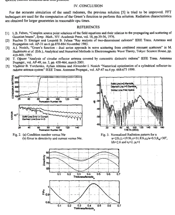
It is observed that the convergence criteria indicated in principle really satisfied and this is shown in Figure 2. Figure 3 presents the normalized radiation pattem for free space and in the presence of radome. It is also seen in this figure that half wavelength design really reduces the distortion in the pattem and it approaches to the free space pattem. Finally in Figure 4 the variation of the directivity and normalized total power with respect to the radome thickness is shown for various feed positions. For a specific rJa value, the directivity is increased more then the free space value if the thickness is taken as 0.555h. Although the absolute excess is almost same with the case given in
[SI,
the relative increase in directivity is low for this larger case. The same figure also presents the10’” Int. Conf. on Mathematical Methods in Elecm“gneticThmnl
M M ~ T * W
5eot. 14-17.2004, Dniemooetmvsk. Ukrainetotal power variation with the radome thickness and a small amount of increase is observed for the indicated specific radome thickness and feed position.
IV. CONCLUSION
For the accurate simulation of the small radomes, the previous solution [ 5 ] is tried to be improved. FFT techniques are used for the computation of the Green’s function t o perform this solution. Radiation characteristics are obtained for larger geometries in reasonable CPU times.
REFERENCES
[l] L.B. Felsen, “Complex source point solutions of the field equations and their relation to the propagating and scattering of Gaussian beams”, Symp. Math.. N Y Academic Press, vol. 18, pp.39-56,1976.
12) Pinchas D. Einziger and Leopold B. Felsen “Ray analysis of two-dimensional radomes“ IEEE Trans. Antennas and Propagation vol. AP-31 110.6 pp.870-884 November 1983.
[3] A.I. Nosich, ”Green’s function
-
dual series approach in wave scattering from combined resonant scatterers” in M. Hashimoto et el (E&.), Analytical and Numerical Methods in Electromagnetic Wave Theory, Tokyo: Science House, pp.419469,1993,
[4]
T.
OgUZer “Analysis of circular reflector antenna covered by concentric dielecmc radome” IEEE Trans. Antennas Propagat., vol. AP-49, no. 3, pp. 458-464, march 2001.[ 5 ] Vladimit B. Yurchenko, Ayhan Altintas and Alexander 1. Nosich “Numerical optimization of a cylindrical reflector-in- radome antenna system” IEEE Trans. Antennas Propagat., vol. AP-47 no.4 pp. 668-673 1999.
Fig. 2. (a) Condition number versusNtr Fig. 3. Normalized Radiation panem far a
(b) E R O ~ in directivity and current VCISUS Ntr. a=25A,L=19.9hc=31.83A,rda=O.5,e~~~30“, kb=?.6 and %=2, ~ = 1
,
. . . : .. .,,. ... a0.9 ,. . / - : . . I _ .. . , . . : ..z
0.8 .... ., !.. . . . ... . _ . j . . 0.1 0.2 0.3 0.4 0.5 0.6 0.7 -b.Fig. 4. Variation of the directivity and normalized total power versus radome thickness for various feed positions. a=15 h L=IO
L
c=18h
0,=30”, %=2, &=l, kb=2.6, PO“ and Ntr==190. Solid c w e is the rda=0.526 (optimized one), Dashed curveis the rda=O.SS and Dotted c w e is the r,Ja=O.Sl. Free space directivity 79.51for rda=0.526.