Morphological Control of Mesoporosity and Nanoparticles within
Co
3
O
4
−CuO Electrospun Nanofibers: Quantum Confinement and
Visible Light Photocatalysis Performance
Amaresh C Pradhan
*
and Tamer Uyar
*
Institute of Materials Science & Nanotechnology, UNAM-National Nanotechnology Research Center, Bilkent University, Ankara, 06800, Turkey
*
S Supporting InformationABSTRACT: The one-dimensional (1D) mesoporous and interconnected nanoparticles (NPs) enriched composite Co3O4−CuO nanofibers (NFs) in the ratio Co:Cu = 1/4
(Co3O4−CuO NFs) composite have been synthesized by electrospinning and calcination of mixed polymeric template. Not merely the mesoporous composite Co3O4−CuO NFs but also single mesoporous Co3O4 NFs and CuO NFs have been
produced for comparison. The choice of mixed polymer templates such as polyvinylpyrrolidone (PVP) and polyethylene glycol (PEG) for electrospinning is responsible for the formation of 1D mesoporous NFs. The HR-TEM result showed evolution of interconnected nanoparticles (NPs) and creation of mesoporosity in all electrospun NFs. The quantum confinement is due to NPs
within NFs and has been proved by the surface-enhanced Raman scattering (SERS) study and the UV−vis−NRI diffuse reflectance spectra (DRS). The high intense photoluminescence (PL) spectra showing blue shift of all NFs also confirmed the quantum confinement phenomena. The lowering of PL spectrum after mixing of CuO in Co3O4nanofibers framework (Co3O4− CuO NFs) proved CuO as an efficient visible light response low cost cocatalyst/charge separator. The red shifting of the band gap in composite Co3O4−CuO NFs is due to the internal charge transfer between Co2+to Co3+and Cu2+, proved by UV−vis
absorption spectroscopy. Creation of oxygen vacancies by mixing of CuO and Co3O4 also prevents the electron−hole
recombination and enhances the photocatalytic activity in composite Co3O4−CuO NFs. The photocurrent density, Mott− Schottky (MS), and electrochemical impedance spectroscopy (EIS) studies of all NFs favor the high photocatalytic performance. The mesoporous composite Co3O4−CuO NFs exhibits high photocatalytic activity toward phenolic compounds degradation as compared to the other two NFs (Co3O4NFs and CuO NFs). The kinetic study of phenolic compounds followedfirst order rate
equation. The high photocatalytic activity of composite Co3O4−CuO NFs is attributed to the formation of mesoporosity and interconnected NPs within NFs framework, quantum confinement, extended light absorption property, internal charge transfer, and effective photogenerated charge separations.
KEYWORDS: electrospinning, nanofibers, quantum confinement, mesoporous, phenolic compounds, visible light
1. INTRODUCTION
Semiconductor photocatalysis, a promising green technology, has attracted significant attention because of its high perform-ance in environmental pollution control.1,2 Phenolic com-pounds are toxic organic byproducts produced during the manufacturing process of agrochemicals, dyes, and pharma-ceuticals.3,4Most of these compounds have been listed as toxic priority pollutants by the European community and U.S. (Environmental Protection Agency).5 Nanostructured materi-als, especially metal and metal oxide nanoparticles, nanoplates, nanorods, nanotubes, and nanofibers, have attracted particular interest in catalytic applications because of their unique optical properties, versatile catalytic activities, and high surface areas.6−8Among them, one-dimensional (1D) structures have a great deal of attention due to their superior charge transport
properties, few grain boundaries, and the quick ion diffusion at the semiconductor−phenolic compounds solutions inter-face.9,10 1D nanostructures such as metal oxide nanofibers (NFs) by electrospinning have remarkable characteristics, e.g., high porosity, a large surface area to volume ratio, and excellent substrates for secondary nanostructures.11,12 The metal oxide Co3O4is a visible light active p-type semiconductor (1.48 eV)
with attractive electronic and structural properties.13But bulk Co3O4 has limitation in photocatalytic activity. In order to make Co3O4an effective photocatalyst, it is a necessary to make
a heterojunction with other semiconductor, resulting in
Received: June 23, 2017
Accepted: September 26, 2017
Published: September 26, 2017
www.acsami.org
enhanced photocatalytic activity due to lowering of electron− hole recombination.14,15Hence, mixture of Co3O4with other
semiconductor oxides could fulfill the electron−hole separation strategy. The other strategy is morphology and structural framework of Co3O4. Recently, Co3O4 nanofibers fabricated
from spiral electrospinning have been utilized as a catalyst for the oxidation of formaldehyde.16The best option is to choose semiconductor oxides having cocatalyst property. A cocatalyst can enhance the photocatalytic activity of a semiconductor by (i) suppressing the electron−hole recombination by trapping the photogenerated electrons, (ii) improving the photostability of the catalyst by consumption of photogenerated charges, particularly holes, and (iii) lowering the activation energy and hence catalyzing the reactions.17 Transition metal oxide semiconductor CuO (1.2 eV) has been reported as cocatalyst to enhance the photocatalytic activity. Shah et al. observed high photocatalytic activity of Ag/AgCl/TiO2 by using CuO as
cocatalyst.18Photodegradation activity of organic substance by WO3has been enhanced by using CuO as cocatalyst.
19 Hence, design and combination of semiconductor Co3O4 and semi-conductor CuO cocatalyst NFs could improve the visible light photocatalytic performance. The design and mixed modi fica-tion of Co3O4and CuO include (i) morphological modification
such as mesoporosity and NPs within NFs, (ii) quantum confinement effect, and (iii) combination of reactive facets of two oxides NFs.
Construction of mesoporous structure within NFs can also enhance the photocatalytic performance.16The construction of mesoporous structures in single Co3O4 and CuO and in mixture of both can elevate the surface area of the photocatalyst which results in the increase of a large number of reactive sites. It can also enhance the light absorption efficiency because of more photons being distributed onto the surface of the photocatalyst, using the pores as light transfer paths.20 Moreover, mesoporous materials themselves can be used as a support of guest materials.21 The surface texture of Co3O4, CuO, and mixture of both NFs can be constructed by adopting electrospinning process. It has been noted the electrospinning process aids the creation of porous and well-ordered NFs by adding suitable optimized block copolymer template and other additives like acid and appropriate solvent.22,23Hence, mixing of polyvinylpyrrolidone (PVP) and polyethylene glycol (PEG) solutions as mixed polymeric template may fulfill the porous NFs/porous NPs within NFs strategy. The vital benefit of electrospinning process is the formation of surface hydroxyl (−OH), which also plays a significant role in its photocatalytic activity.24
Hence, formation of mesoporosity within the composite Co3O4−CuO NFs could enhance the surface reactive sites and
light absorption property. Furthermore, quantum confinement effects generated from quantum dots have been investigated intensively.25 When the crystal size of the semiconductor is close to its exciton Bohr radius, its band gap will be enlarged while the crystal size is decreased.25So formation of NPs within NFs could provide the quantum confinement phenomena and will lead to enhanced light absorption property. Moreover, the combination of reactive facets of Co3O4and CuO NFs can act as an efficient composite photocatalysts for phenolic compound degradation. It has been noted that the mesoporous Co3O4
exposed {110} facets showed high activity in oxidation of ethylene.26 Xie et al.27 observed that the Co3O4 nanorods,
which predominantly exposed their {110} facets, favoring the presence of active Co3+species at the surface, exhibited a much
higher activity for CO oxidation. Therefore, the synthesis design of nanostructured Co3O4catalysts with highly reactive
crystal facets is a key to exploring different catalytic properties and applications. Thus, fabrication of porous NFs could be the better option for the generation of highly reactive {110} facets. Not merely Co3O4 facets but also CuO exposed with {001}
facets have high reactive sites for gas sensing and Li-ion battery application.28So combination of both mesoporous Co3O4and
CuO NFs with their respective reactive facets could enhance the photocatalytic properties.
In this article, we report the practical approach for the fabrication of mesoporous Co3O4 NFs, CuO NFs, and
composite Co3O4−CuO NFs by in situ electrospinning process. The mixed polymeric templates (PVP and PEG) have taken the key role for the fabrication of above-mentioned electrospun mesoporous NFs (Co3O4NFs, CuO NFs) and Co3O4−CuO
composite NFs. Here, we have explored the mechanistic pathways for the formation of mesoporous and NPs within all fabricated electrospun NFs. It is investigated that the quantum confinement effect arises due to the formation of NPs within NFs, proved by SERS analyses. We have also explored the mechanism of the photocatalytic phenolic compound degrada-tion process and the quantum confinement induced visible light photocatalytic activity of mesoporous composite Co3O4−CuO
NFs. In the present study, it is also explained that the role of CuO is as a cocatalyst which enhanced the photocatalytic activity in the composite Co3O4−CuO NFs by separation of charge carriers and suppress their recombination. Under the combined action of Co3O4 and CuO, the as-synthesized mesoporous composite Co3O4−CuO NFs exhibits the highest
photocatalytic activity compared with the other two single mesporous NFs. This is explained by the enhanced morphology, textural property, and optical properties.
2. EXPERIMENTAL SECTION
2.1. Materials. All the chemicals and reagents are of analytical grade and used without further purification. Cu(II) acetate (98%, Aldrich), Co(II) acetate (98%, Aldrich), polyethylene glycol(PEG, Mw = 1000 g/mol, Sigma-Aldrich), polyvinylpyrrolidone (PVP, Mw = 1 300 000 g/mol, Aldrich), isopropanol (95.5%, Sigma-Aldrich), acetic acid (100%, Sigma), 4-chlorophenol (99%, Alfa Aesar), 4-nitrophenol (99%, Alfa Aesar), phenol (99%, Alfa Aesar), nitric acid (Sigma), ammonia (Sigma), rhodamine 6G (98%, Sigma), potassium iodide (98%, Aldrich), and p-benzoquinone (98.5%, Alfa Aesar) were used in the present study.
2.2. Electrospinning of Mesoporous CuO NFs, CuO NFs, and Porous CuO Nanoflower. In order to optimize the mesoporous CuO NFs strategy, the Cu(II) acetate was taken as precursor of CuO. The experimental procedure proceeded by taking 0.5 g of Cu(II) acetate dissolved into the mixture of 1 g of PVP and 0.5 g of PEG (PVP:PEG = 3:1) in 10 mL of isopropanol. The reaction solution was stabilized by adding 1 mL of acetic acid. The whole solution was stirred for 24 h prior to electrospinning. Further, the solution wasfilled in a 3 mL plastic syringe with needle diameter of 0.4 mm and placed on a syringe pump (KDS101, KD Scientific, USA). The flow rate of the polymer solution was controlled by the syringe pump atfixed rate of 0.5 mL h−1. The electric field (15 kV) was applied from a high voltage power supply (Spellman, SL series, USA). The sample was collected on aluminum foil which was grounded by metal collector at a distance 17 cm from the needle tip. Electrospinning procedure was carried out at 23°C and 18% relative humidity in a Plexiglas box. Finally, the mesoporous CuO NFs were fabricated by calcining the PVP/CuO/PEG composite nanofibers at 450 °C for 4 h in air. The materials and the representative SEM images are summarized in the
Scheme 1. Similarly, CuO NFs were prepared by taking only PVP as polymer template. The other parameters like concentration of
isopropanol, acetic acid and amount of Cu(II) acetate were similar to those of mesoporous CuO NFs. The CuO NFs were prepared by calcining PVP/CuO at 450°C for 4 h. Moreover the porous CuO nanoflowers were prepared only by using the PEG as a polymeric template. Since PEG is a low molecular weight matrix, electrospraying was occurred instead of electrospinning in which particles were formed instead offibers. The concentrations of isopropanol, acetic acid, and amount Cu precursor were similar to those for mesoporous CuO NFs and CuO NFs. Finally, porous CuO nanoflowers were produced by calcining PEG/CuO at 450 °C for 4 h (Scheme 1). Thus, it was understood that the mixture of PVP and PEG was responsible for the formation of mesoporous CuO NFs whereas the use of only PVP and PEG yielded the formation of CuO NFs, and porous CuO nanoflowers, respectively. In order to adopt the mesoporous NFs strategy, the other oxides such as mesoporous Co3O4 NFs and
mesoporous composite Co3O4−CuO NFs have been prepared by
using the mixture of PVP/PEG matrix, and the details are given in the following section.
2.3. Electrospinning of Mesoporous Co3O4 NFs and
Mesoporous Composite Co3O4−CuO NFs. For the synthesis of
mesoporous Co3O4 NFs and mesoporous composite Co3O4−CuO
NFs, the optimal conditions/parameters were applied, like the electrospinning of mesoporous CuO NFs, i.e., using mixed PVP/ PEG polymeric matrix. The mesoporous Co3O4NFs are fabricated by
taking 0.5 g of cobalt(II) acetate as a precursor. The synthesis process was followed in a similar way as mesoporous CuO NFs. Finally, the Co3O4NFs were formed by calcined the PVP/Co3O4/PEG composite
at 450°C for 4 h in air. The mesoporous composite Co3O4−CuO NFs
were fabricated by electrospinning method by taking a mixture of Co(II) acetate and Cu(II) acetate as a precursor, respectively. Composite Co3O4−CuO NFs (Co:Cu = 1/4) were synthesized by
taking a calculated amount of Co(II) and Cu(II) acetate in the mixture of PVP:PEG = 3:1, in isopropanol and acetic acid. The whole solution was stirred for 24 h before electrospinning. Lastly, the mesoporous composite Co3O4−CuO NFs were fabricated by the calcinations of
PVP/Co3O4−CuO/PEG composite at 450 °C for 4 h in air. The
mesoporous composite Co3O4−CuO NFs in the ratio Co:Cu = 1/4
are denoted as Co3O4−CuO NFs. In a similar way, Co3O4−CuO NFs
(Co:Cu = 1/3) and Co3O4−CuO NFs (Co:Cu = 1/2) have been
synthesized for comparison of photocatalytic performance.
2.4. Characterization. The specific surface area, pore size, and pore volume of mesoporous NFs were measured by N2 sorption
method at liquid nitrogen temperature (−196 °C) using Quantach-rome Instrument Autosorb (iQ2). The specific surface area and pore
size distribution were estimated based on Brunauer−Emmett−Teller (BET) and Barrett−Joyner− Halenda (BJH) methods, respectively. The crystal structures of the nanofibers were characterized using a PANalyticalX’Pert Pro multipurpose X-ray diffractometer (XRD) in the range of 2θ = 10−80° with Cu Kα (1.5418 Å) radiation. The surface morphology and elemental composition of mesoporous NFs were analyzed by field emission scanning electron microscopy (FE-SEM, Quanta 200 FEG, FEI). The morphology and mesoporosity of the nanofibers were examined by high resolution transmission electron microscope (HRTEM, Tecnai G2 F30, FEI). The scanning trans-mission electron microscopy−energy dispersive X-ray (STEM-EDX) analysis was used to study composition of the metal oxides within the nanofibers. The diameter of the NFs was calculated by ImageJ software. The UV−vis absorption spectra of the mesoporous NFs were recorded by UV−vis spectrophotometer (Varian Cary 100). The UV− visible−near-infrared diffuse reflectance spectra (UV−vis−NIR DRS) of the NFs were recorded by UV−vis−NIR spectrophotometer (Cary 5000). The photoluminescence spectra were measured on a fluorescence spectrometer (FL-1057 TCSPC) with an excitation wavelength at 390 nm light. Raman spectra measurement was conducted on a scanning near-field optical spectroscopy (SNOM) confocal Raman spectroscope (WITec) with a laser light wavelength of 532 nm. The Fourier transform infrared (FTIR) spectra of the samples were recorded with a Bruker VERTEX 70 in the range of 400−4000 cm−1at room temperature using KBr pellet.
2.5. Visible Light Photocatalytic Degradation of Phenolic Compounds. The visible light photocatalytic degradation of phenolic compounds was examined by taking phenol, 4-chlorophenol (4-CP), and 4-nitrophenol (4-NP) solution. A stock solution of 20 mg L−1for phenol, 4-CP, and 4-NP was prepared and suitably aqueous diluted to the required initial concentration. Prior to photocatalysis, the phenolic compounds solution was stirred for 20 min in order to reach equilibrium. Photocatalytic degradation of phenolic compounds (phenol, 4-CP, and 4-NP) was carried out by taking 10 mL of each solution (20 mg L−1), 1 mg·.mL−1of catalyst dose at pH 6 for 70 min. The pH of the solution was monitored by Mettler Toledo pH meter with proper addition of 0.01 M HNO3and/or NH4OH. The phenolic
compounds solution with catalyst was placed for visible light irradiation (300 W, Osram, sunlight simulation)) at room temperature. The separated reaction solution from catalyst was analyzed UV−vis spectrophotometer (Varian Cary 100). The maximum absorbance of phenol, 4-CP, and 4-NP were at 210, 224, and 316 nm, respectively. 2.6. Surface-Enhanced Raman Spectroscopy. For surface-enhance Raman spectroscopy (SERS) measurements,29500μL of Rh 6G water solution of 20μM was kept under ultrasound with 1 mg of all respective NFs. Then the Rh 6G-absorbed NFs were dispersed in 50μL of water. The suspension of 10 μL was dropped onto a glass slide. The dropped solution spread evenly into a circle. After evaporation of the water, the sample was subjected to Raman measurement. All experiments were carried out at room temperature in the same conditions.
2.7. Active Species Trapping Experiments. The holes and radicals trapping experiments were conducted by adding various scavengers to the mesoporous composite Co3O4−CuO NFs in order
to know the main reactive radical species involved in the photocatalytic process. Three different scavengers such as potassium iodide (KI; 0.1 mmol), isopropyl alcohol (IPA; 0.1 mmol), and p-benzoquinone (BQ; 0.1 mmol) have been used for the detection of holes (h+), hydroxyl
radicals (•OH), and superoxide radical anions (O2•−) species in the
photocatalytic phenolic compound degradation, respectively.30 The trapping experiment is similar to that of the photocatalytic degradation of phenolic compounds. The scavengers are added to the phenolic compounds solutions prior to the photocatalyst.
Scheme 1. Electrosprayed Porous CuO Nanoflowers (Polymeric Matrix, PEG Only), Electrospun CuO NFs (Polymeric Matrix, PVP Only), and Mesoporous CuO NFs (Polymeric Matrix, PEG/PVP Mixture) Obtained after Calcination at 450°C for 4 h
2.8. Photoelectrochemical Measurements. Electrochemical measurements were conducted using a three-electrode electrochemical cell consisting of a platinum wire as the counter electrode, Ag/AgCl electrode as reference electrode, and a prepared electrode as the working electrodefilled with an aqueous solution of 0.1 M Na2SO4.
The electrolyte was saturated with nitrogen gas prior to electro-chemical measurements. The photoelectroelectro-chemical measurements were performed using an Ivum multichannel potentiostat under illumination conditions (λ = 400 nm). Irradiation was performed using a 300 W Xe lamp with a 400 nm cutoff filter.
3. RESULTS AND DISCUSSION
3.1. Porosity of the Nanofibers. N2 sorption isotherms and the pore diameter distributions of all the NFs are shown in
Figure 1a, and a summary of the specific surface area, pore
volume, and average pore diameter data is shown inTable S1 in Supporting Information. All the NFs are of typical IV isotherms with type H3 hysteresis loop according to the Brunauer− Deming−Deming−Teller (BDDT) classification, suggesting the presence of mesoporous structure.31The most important thing is that the materials showed intraparticle mesoporosity or “framework porosity”.32
This is because the hysteresis loops of Co3O4NFs, CuO NFs, and composite Co3O4−CuO NFs start within a relative pressure (P/P0) region of 0.1−0.5.33 The
formation of mesoporous structure within NFs is due to the removal of mixed PVP and PEG polymeric matrix at optimum calcinations temperature (450 °C in 4 h). The pore size distribution curve of all NFs is shown in theFigure 1a (inset). The intense peak of all NFs is at 2−50 nm, the resulting mesoporous range. The BET specific surface area, pore
diameter, and pore volume of the NFs are listed inTable S1. The specific surface areas of Co3O4 NFs, CuO NFs, and
composite Co3O4−CuO NFs are 28, 35, and 39 m2/g,
respectively. The high surface area of NFs will provide more reactive sites for an interaction with phenolic compounds. The pore diameter (Table S1) are in the range of the mesoporous. Hence from the BET isotherm and pore diameter data, it is concluded that all NFs have mesoporous character within framework.
The wide angle XRD patterns of mesoporous Co3O4 NFs,
CuO NFs, and composite Co3O4−CuO NFs are shown in the
Figure 1b. In the XRD pattern of porous Co3O4NFs, the Bragg
reflections at angles of 18.86°, 31.16°, 36.92°, 38.56°, 44.67°, 59.28°, and 65.26° correspond to (111) (220), (311), (222), (400), (511), and (440) main crystal planes indicating the formation of pure cubic crystalline Co3O4(JCDPS, card no.
42-1467). In the XRD pattern of mesoporous CuO NFs, the peaks at angles of 32.49°, 35.59°, 38.80°, 48.87°, 53.52°, 58.39°, 61.49°, 66.25°, 68.14°, 72.46°, and 75.23° were purely assigned to the (110), (002), (111), (−202), (020), (202), (−113), (−311), (220), (311), and (004) crystal planes, respectively. It can be seen that all the diffraction peaks belong to the CuO monoclinic phase (JCPDS 48-1548). The porous composite Co3O4−CuO NFs consisting of reflection planes (111), (220),
(400), (222) (511), and (440) are due to cubic crystalline Co3O4, and crystal planes (002), (111), (−202), and (220) are
due to monoclinic CuO. Hence, the presence of both Co3O4 and CuO reflection planes in mesoporous composite Co3O4−
CuO NFs indicates the formation of Co3O4−CuO composite. 3.2. Morphological Analyses of Mesoporous Nano-fibers. The morphologies of the mesoporous nanofibers were investigated by SEM images. Figure 2 describes the morphology, and Table S1 depicts the diameter of different mesoporous NFs before and after calcination. The PVP/PEG is used as mixed polymeric carrier matrix for the electrospinning of nanofibers. The nanofibrous materials before calcinations (dried 70°C for 6 h) are denoted as, for example, PVP/Co3O4/
PEG, whereas after calcination (removal of PVP and PEG at 450 °C, 4 h) they are denoted as mesoporous Co3O4 NFs.
Similarly, the other NFs can be symbolized in order to describe the SEM morphology. The average diameter of mesoporous NFs is mentioned for all samples. The bead-free nanofibers withfiber diameter of 280 ± 50 nm for PVP/Co3O4/PEG NFs are obtained before calcination (Figure 2a). The rough and mesoporous nanofibers with narrow fiber diameter of 160 ± 30 nm for mesoporous Co3O4NFs are obtained (Figure 2b) after
calcinations of PVP/Co3O4/PEG. Similarly, bead-free and
smoothfibrous morphology having diameter of 400 ± 40 nm is also observed for the sample of PVP/CuO/PEG inFigure 2c, whereas a rough, mesoporous nature and narrow diameter (130 ± 20 nm) for CuO NFs are obtained after calcination as depicted inFigure 2d. A clear mesoporous nature of CuO NFs framework is observed which is consistent with BET result. Moreover,Figure 2e shows the bead-free PVP/Co3O4−CuO/
PEG NFs having diameter of 600± 70 nm with irregular and inhomogeneous structure having rectangular moieties which is marked in arrows. These rectangular moieties disappeared, and creation of mesoporosity appeared within blank space of rectangular voids (Figure 2f) as well as the diameter reduction of the NFs (250± 30 nm) which is due to the combined effect and removal of PVP and PEG in the optimum calcinations temperature, which resulted in mesoporous Co3O4−CuO NFs. Furthermore, in order to examine the role of PEG for
Figure 1.(a) N2sorption isotherm and pore diameter (inset) and (b)
wide-angle X-ray diffractograms of mesoporous Co3O4, CuO, and
composite Co3O4−CuO NFs.
generating mesoporosity, SEM image of porous CuO nano-flower is incorporated in theSupporting Information (Figure S1). The CuO nanoflowers enriched with porous morphology have been obtained from the neat PEG matrix. FromScheme 1,
Figure 2, and Figure S1, it is understood that PEG is responsible for generation of porosity whereas PVP aids to create NFs and mixed PVP/PEG produces mesoporous NFs. The decrease of fiber diameter for all NFs and creation of mesoporosity after calcination is due to the removal/ decomposition of PVP matrix and quick decomposition of PEG, respectively. In short, a combination of high molecular weight polymeric matrix (i.e., PVP) helps the electrospinning of the nanofibers, and low molecular weight polymeric template (i.e., PEG) helps to create mesoporosity once the NFs are calcined in order to obtain inorganic NFs by removal of polymeric components.
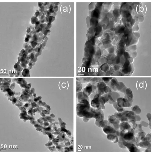
The TEM and HR-TEM analyses of the mesporous NFs have been performed in order to study the morphology and
formation of nanoparticles (NPs) within NFs (Figure 3). Parts a and b of Figure 3 describe the TEM images of the mesoporous Co3O4 NFs. The highly porous nature is clearly
observed, i.e., mesoporous within the Co3O4 NFs which was
consistent with the BET analyses. The vital aspect of the present study is that Co3O4NPs are interconnected in such a
way that also aids formation of an empty void (mesoporosity). The particle size of the Co3O4NPs is 16.5± 4 nm (Table S1). The formation of the mesoporus and NPs within NFs can have an architecture as “mesoporous−NPs−Co3O4 NFs”. The
similar micrographs were observed in the case of the mesoporous CuO NFs (Figure 3c,d) and also followed the similar architecture, i.e., “mesoporous−NPs−CuO NFs”. The size of the interconnected CuO NPs is 20.0± 2.0 within CuO NFs. Hence, mesoporosity and interconnected NPs within both mesoporous CO3O4 and CuO NFs will enhance the surface
reactive site and visible light absorption property through quantum confinement phenomena, respectively. These
phe-Figure 2.Representative SEM images of (a) PVP/Co3O4/PEG, (b) mesoporous Co3O4NFs, (c) PVP/CuO/PEG, (d) mesoporous CuO NFs, (e)
PVP/Co3O4−CuO/PEG, and (f) mesoporous Co3O4−CuO NFs.
nomena will be helpful for an efficient photocatalytic degradation of phenolic compounds in the visible light. The lattice fringes from HR-TEM and selected area electron diffraction (SAED) pattern of the Co3O4 NFs are displayed
in the Figure S2a,b. The lattice spacing 0.286 nm is due the
presence of Co3O4with the plane (220) within the mesoporous
Co3O4NFs.
34
The SAED pattern exhibits the diffraction rings (111), (220), (311), and (222) of a spinel structure of Co3O4 in mesoporous Co3O4 NFs. The inset image in Figure S2b
shows the fast Fourier transform (FFT) diffractogram from the
Figure 3.Representative TEM micrographs of mesoporous Co3O4NFs (a, b) and mesoporous CuO NFs (c, d).
Figure 4.Representative micrographs of mesoporous composite Co3O4−CuO NFs: (a, b) TEM images; (c) HR-TEM image (lattice fringes); (d)
SAED pattern; (e−h) EDAX mapping patterns.
mesoporous Co3O4 NFs with {110} direction.21The exposed surface active facets {110} are more reactive in the mesoporous Co3O4NFs, which could absorb visible light efficiently.Figure
S2cshows the HR-TEM image along with lattice spacing, and
Figure S2dshows the SAED pattern of mesoporous CuO NFs. The lattice spacing 0.240 nm for (111) plane is due to the CuO monoclinic phase.35The SAED pattern exhibits the diffraction rings (110), (002), and (111), corresponding to the presence of CuO in the mesoporous CuO NFs. The facets {001} are observed from FFT diffractogramFigure S2d(inset), which is the highly active facets of the CuO.28The reactive facets {110} from Co3O4 and {001} from CuO will enhance the
photocatalytic properties through light absorption phenomena. The TEM and HR-TEM images of the mesoporous composite Co3O4−CuO NFs are shown in Figure 4, and particle size within NFs is listed in theTable S1. Figure 4a,b shows that the porous nature, i.e., mesoporous, is confirmed from BET analyses. The TEM imaging (Figure 4a,b) also indicated that the enriched Co3O4 and CuO NPs are
interconnected with each other within composite Co3O4− CuO NFs. The particle size of NPs within composite Co3O4−
CuO NFs is measured as 15.2± 3.0 nm (Table S1). Hence, the architecture of “mesoporous−NPs−Co3O4−CuO NFs” is
formed which is similar to those of the other two NFs (Co3O4 NFs and CuO NFs). From the HR-TEM imaging
(Figure 4c), the lattice spacing of 0.284 nm for Co3O4(220)
and 0.239 nm for CuO (111) was measured within the mesoporous composite Co3O4−CuO NFs.34,35The decrease of
the lattice spacing in Co3O4 and CuO within composite as compared to the neat Co3O4 and CuO NFs is due to the
formation of the composite Co3O4−CuO NFs. The lattice fringes showing the polycrystalline nature are due to the presence of Co3O4and CuO. The SAED pattern (Figure 4d)
exhibits the diffraction rings (111), (220), (311), (222), and (400) corresponding to the crystalline nature of the spinel structure of Co3O4, and the plane corresponding to (002), (111), and (−202) is due to the monoclinic structure of CuO (marked in red) within mesoporous composite Co3O4−CuO
NFs. The polycrystalinity nature of mesoporous Co3O4−CuO
NFs is also helpful for enhancement of the light absorption property. In order to confirm the distribution of elements and reactive sites on the surface of mesoporous composite Co3O4−
CuO NFs, EDAX elemental mapping analysis is employed (Figure 4e−h). The EDAX mapping results revealed the high content of Co as compared to Cu in Co3O4−CuO NFs, which
is consistent with the experimental condition. The EDAX elemental analyses of mesoporous Co3O4NFs, CuO NFs, and
composite Co3O4−CuO NFs reveal the presence of respective elements in each sample of NFs (Figure S3).
3.3. Optical Analyses of Mesoporous Nanofibers. The optical properties such as absorption edges, effect of composite on the electronic structure, and band gap energy of the mesoporous Co3O4 NFs, CuO NFs, and composite Co3O4−
CuO NFs are studied by using UV−visible absorption spectra (Figure 5a). The entire mesoporous NFs showed strong absorption band at 200−300 nm, which is due to the ligand to metal charge transfer (LMCT) between oxygen and metal center within the NFs. The mesoporous CuO NFs exhibit continuous and enhanced light absorption in the range of 400− 800 nm. This is due to the efficient harvesting of visible light. Moreover, the octahedrally coordinated Cu2+ species is observed at 600−800 nm which is due to the d−d transition band.36A broad peak starting from 400−670 nm is due to the
d−d transitions of Co3+ in octahedral sites and Co2+ in
tetrahedral sites in mesoporous Co3O4 NFs.37 The d−d
transition of octahedral and tetrahedral sites helps light absorption in the visible region. The mesoporous composite Co3O4−CuO NFs shows the dual behavior of d−d transitions
of Co3+and Co2+along with Cu2+charge transfer in the peak
region 400−712 nm. The dominant nature Co3O4absorption
peak in composite Co3O4−CuO NFs is due to the composition
of high amount of Co3O4with less amount of CuO. The most
interestingfinding of the present investigation is the rising or red shifting of peaks from 720 to 800 nm in all mesoporous NFs. This phenomenon may be due to the creation of quantum confinement phenomena in mesoporous Co3O4 NFs, CuO
NFs, and composite Co3O4−CuO NFs. All presently fabricated
NFs showing red shifts which favor high photocatalytic applications in the visible region. The band gap energy of all NFs materials can be calculated by using the following equation.38
α νh =A h( ν−Eg)n
where α, ν, A, and Eg are the absorption coefficient, light frequency, proportionality constant, and band gap, respectively. The band transition depends upon the value of n = 1/
2 for
direct transition and n = 2 for indirect transition. It is examined that all the mesoporous NFs show direct allowed transitions. The band gap energies of the all NFs can be estimated from the plots of (αhν)2versus photon energy (hν). The intercept of the
tangent to the X axis would give a good approximation of the band gap energies for the NFs samples, as shown in Figure 5b,c,d. The band gap of mesoporous CuO NFs (Figure 5b) is found to be 1.50 eV, which belongs to the visible light response semiconductor. The observed band gap value is wider than the bulk CuO (1.2 eV), which is due to the quantum confinement effect for mesoporous CuO NFs. The wider band gap of mesoporous CuO NFs as compared to bulk is due to efficient light absorption by mesoporous NPs and crystalline CuO NFs, confirmed from TEM and HR-TEM analyses. It is well-understood that the reduction in particle size results in
Figure 5. (a) UV−visible absorption spectra of mesoporous NFs samples, showing plots of (αhν)2vs photon energy (hν) for the band
gap energy of (b) mesoporous CuO NFs, (c) mesoporous Co3O4NFs,
and (d) mesoporous composite Co3O4−CuO NFs.
increased surface/volume ratio.39 The increase of band gap energy in NFs as compared to bulk material is due to the lowering of the coordination number and atomic interaction of surface atom which leads to increases of the highest valence band energy and decreases of the lowest unoccupied conduction band energy.40 The mesoporous Co3O4 NFs
(Figure 5c) has two Egwith values of 1.62 (Eg1) and 2.01 eV
(Eg2), which agreed with the band structure of Co3O4with Co3+
t2g→ Co2+t2g(Eg1) and O2−→ Co2+t2g(Eg2) charge-transfer
transition, respectively.41 It is evaluated that the band gap values for bulk Co3O4are 1.48 eV (Eg1) and 2.19 eV (Eg2).13
The Eg1value Co3O4NFs is 1.62 eV which is wider than the Eg1 value of bulk Co3O4 (1.48 eV). This is due to the quantum
confinement effect and lattice contraction. Furthermore, the Eg2
value of Co3O4 NFs is 2.01 eV which is smaller than the Eg2
value of bulk Co3O4(2.19 eV). This can be attributed to several
factors such as lattice expansion and/or the presence of defects (mainly vacancies) in the intergranular regions which forms the donor and acceptor bands.42 The mesoporous composite Co3O4−CuO NFs (Figure 5d) has band gap of 1.55 eV. The
narrow band gap as compared to Co3O4 NFs is due to the formation of localized state by intermixing of Co 2p and Cu 2p. The most interestingfinding is that the band gap of Co3O4− CuO NFs is wider than the bulk CuO and Co3O4, which proves
the availability of quantum confinement effect and defect/ vacancies sites. Hence, the optical properties of the fabricated mesoporous NFs have quantum confinement, defect/vacancies, and suitable band gap which could enhance the light absorption property in the visible region for an efficient photocatalytic degradation of organic pollutants.
In order to prove the quantum confinement phenomena more clearly within mesoporous NFs, the UV−vis−NRI DRS studies have been performed and the obtained spectra were given in theSupporting Information (Figure S4). In the UV− visible absorption spectra (Figure 5a), the optical behavior of the mesoporous NFs from 200 to 720 nm is already discussed. Hence, in the UV−vis−NRI DRS, the discussion regarding optical properties of the fabricated NFs was focused from 720 to 2000 nm. The interesting and rarefinding observed is that all mesoporous NFs have the quantum confinement effect. The high red shifting peaks starting from nearly 780 to 1000 nm is due to the quantum confinement effect for all NFs. The d−d transition band for tetrahedrally coordinated Cu2+ species
appears around 1300−1600 nm for CuO NFs.43In both Co3O4
NFs and Co3O4−CuO NFs, the shoulder peak starting from 1020−1210 nm is due to the “intervalence” charge-transfer Co2+ → Co3+ and the peak at 1700 nm is attributed to the
4A
2(F)→4T1(F) transition in the Co3O4structure. The charge
transfer transition represents an internal oxidation−reduction process which facilitates photocatalytic process in the visible region. Hence, from UV−visible absorption and UV−vis−NRI DRS spectra it is concluded that high red shifting of all mesoporous NFs is due to the quantum confinement effect and the internal charge transfer within Co2+and Co3+and Cu2+.
The photoluminescence (PL) emission spectra describe the effectiveness of the charge carrier trapping, immigration, and transfer behaviors of the photoexcited electron−hole pairs in semiconductors. The PL emission (λexc = 390 nm) spectra of
semiconductor mesoporous Co3O4 NFs, CuO NFs, and
composite Co3O4−CuO NFs are shown in Figure 6. For all mesoporous NFs the peaks centered at 442, 470, and 550 nm correspond to the blue, green, and yellow-orange bands, respectively. The blue-shift behavior of the intense peak
position at 442 nm for all NFs is due to the Burstein−Moss effect resulting from nanostructure materials, which is provided with the enhanced quantum confinement effect.44The intense peak for all NFs at blue region is due to the electron excitation, and the weak green emission (470 nm) is due to the deep level defect.45Moreover, the yellow-orange shift (550 nm) is due to the oxygen vacancies (Vo). For mesoporous Co3O4 NFs, the emission peaks 442, 470, and 550 nm correspond to charge transfer O2−→ Co2+process, O2−→ Co3+charge transfer, and
oxygen vacancies (Vo), respectively.46 Likewise, mesoporous
CuO NFs exhibit the copper vacancy (VCu), Cu interstitial (ICu), oxygen vacancy (Vo) corresponding to the emission
peaks at 442, 470, and 550 nm, respectively.47The mesoporous composite Co3O4−CuO NFs also show the blue and
yellow-orange emission peaks, resulting quantum confinement effect, and oxygen vacancies. From the above investigation, it is well-understood that the all mesoporous NFs exhibit quantum confinement effect (blue region), crystal defect (green region), and oxygen vacancies (yellow-orange region). Quantum confined effect provides high light absorption property of nanofibers due presence of NPs within all NFs, which provides high surface to volume ratio. According to the Marcus theory, quantum confined effect favors higher rates of interfacial charge transfer due to the increased thermodynamic energy of the confined electron−hole pairs.48Hence, formation of interfacial charge transfers in all NFs increases the generation of electron− hole for photocatalytic application in visible region. The defect level indicates the radiative recombination resulted in increase in the PL intensity.49 The green emission peak (470 nm) completely vanished in the case of mesoporous composite Co3O4−CuO NFs as compared to Co3O4 and CuO NFs, indicating the prevention of electron−hole recombination. This phenomenon proves the role of CuO as cocatalyst in Co3O4. Moreover, the oxygen vacancies of all NFs are situated at 550 nm. Oxygen vacancies aid to trap the photoemission electron from conduction band of fabricated NFs via nonradiative transition. This phenomenon prevents the electron−hole recombination and resulting swift photocatalytic degradation of phenolic compounds in visible light. Furthermore, the Schottky barrier appears to be due to the mixing of the CuO into the Co3O4. This phenomenon also helps to create superficial space charge layer between valence and conduction band of Co3O4 NFs, which could act as an electron sink to efficiently prevent the electron−hole recombination.50That is why PL intensity gradually decreases from Co3O4NFs > CuO NFs > Co3O4−CuO NFs.
3.4. Chemical Structure Analyses of Nanofibers. X-ray photoelectron spectroscopy (XPS) analysis has been performed
Figure 6. Photoluminescence spectra of mesoporous Co3O4, CuO,
and composite Co3O4−CuO NFs.
to investigate the electronic environment and oxidation state of mesoporous composite Co3O4−CuO NFs (Figure 7). It has
been investigated that the main peaks are at ∼933.4 eV (Cu 2p3/2) and 953.2 eV (Cu 2p1/2), along with the presence of
their characteristic shakeup satellite peaks at approximately 941.3 and 961.5 eV, respectively, which are due to the existence of pure CuO.51In the present study, the binding energy (BE) of Cu 2p3/2and Cu 2p1/2is at approximately 933.77 and 953.71
eV, indicating fully oxidized CuO52in mesoporous composite Co3O4−CuO NFs. The shakeup satellite peaks located at
approximately 940.75, 942.80, and 961.37, 962.41 eV are attributed to the Cu (3d) hole states.53These satellite peaks also confirm the Cu(II) bonding state of CuO in the composite Co3O4−CuO NFs.54The XPS spectrum of Co 2p in Figure 7
shows that the peaks at approximately 780.52, and 795.70 eV correspond to Co(III) 2p3/2and 2p1/2, while 783.4 and 798.6
eV correspond to Co(II) 2p3/2 and 2p1/2, respectively. The weak 2p3/2satellite peaks are found at approximately 786.6 and
790.01 eV, and those of 2p1/2 satellite peaks are found at approximately 802.00 and 805.30 eV.55These peaks represent the existence of Co(II) in the tetrahedral sites and Co(III) in the octahedral sites of Co3O4 in the mesoporous composite
Co3O4−CuO NFs. The observed energy separation between Co(III) 2p3/2 and Co(III) 2p1/2 peaks is 15 ± 0.2 eV,
corresponding to the Co3O4. The O 1s BE in composite Co3O4−CuO NFs is observed at ∼528.54 eV and is due to the
strong interaction of O with Co and Cu in mesoporous composite Co3O4−CuO NFs, whereas peak at ∼530.63 eV
(lattice oxygen) is due to the surface hydroxyl present in the mesoporous composite Co3O4−CuO NFs.56From the above
results it is concluded that the higher of BE of Co 2p as compared to pure Co 2p (Rakibuddin et al.)57and lower BE of 528.54 eV as compared to 529 eV pure Co3O457are due to the electron transfer from Co(II)/Co(III) to Cu(II) through O
atom and forming the −Co−O−Cu− linkage in the
mesoporous composite Co3O4−CuO NFs.
The FTIR spectra of Co3O4NFs, CuO NFs, and Co3O4− CuO NFs are displayed in theFigure S5. The FTIR spectrum
of the mesoporous Co3O4NFs exhibits two distinct bands at 567 and 663 cm−1and are due to the stretching vibrations of the metal−oxygen bonds.58
The first band at 567 cm−1 is assigned to the OB3 vibration, where B denotes Co3+ in the
octahedral hole. The band at 663 cm−1is assigned to the ABO3
vibration, where A denotes Co2+in the tetrahedral hole. Hence,
nature of the mesoporous Co3O4 NFs is spinel lattice. The
Cu−O stretching vibration observed at 535 cm−1is due to the formation of CuO in mesoporous CuO NFs.59The stretching frequencies 553 and 661 cm−1are due to the presence of Co3+/ Cu2+ and Co2+ in the mesoporous composite Co
3O4−CuO
NFs, respectively. That means the formation of spinel Co3O4
and CuO is observed within composite Co3O4−CuO NFs. The SERS experiment was performed by incident of laser (532 nm) to the bare mesoporous Co3O4NFs, CuO NFs, and composite Co3O4−CuO NFs in comparison with addition of
probe molecule rhodamine 6G (Rh 6G) mixed with mesoporous NFs separately (Figure S6). From Figure S6, it is investigated that all the mesoporous NFs mixed with Rh 6G have high enhancement of Raman intensity as compared to neat mesoporous NFs. The enhancement of Raman intensity is due to the presence of NPs within the mesoporous NFs. The NPs present in all the mesoporous NFs efficiently adsorb Rh 6G because of the quantum confinement phenomena, which leads to the absorption of the laser radiation and enhancement of the Raman intensity of Rh 6G. This enhancement of Raman intensity in the presence of NPs within mesoporous NF is called as SERS enhancement. The SERS signals due to the addition of Rh 6G are 1646 cm−1, 1567 cm−1, 1495 cm−1, 1362 cm−1, 1309 cm−1, and 1184 cm−1. These Raman signals arose from the totally symmetric modes of in-plane C−C stretching vibrations of Rh 6G.60 The Raman band at 772 cm−1 was assigned to the C−H out-of plane bending vibration of Rh 6G. The shift at 608 cm−1 was assigned to the in-plane bending vibration of the Rh 6G C−C−C ring.61 The SERS enhance-ment is based on the two types of mechanisms: thefirst is the electromagnetic enhancement, which is caused by a strong surface plasmon resonance of the nanoparticles metal surface coupled to the incident light.62 The second is the chemical enhancement, which can be considered to be a resonance Raman process between the ground electronic state of the molecule−metal complex and its new excited levels arising from charge transfer between the metallic surface and the adsorbed molecule.63 It should be noted that semiconductor materials have dominant contribution for the SERS signal, which must involve a charge-transfer mechanism since surface plasmon resonances lie far in the infrared.63 In the present context, interconnected NPs situated in the mesoporous Co3O4 NFs, CuO NFs, and composite Co3O4−CuO NFs belong to
semiconductor, interacting with molecule (Rh 6G) through charge transfer mechanism. It has been noted that the quantum confinement phenomenon arises in the small size of the semiconductor NPs. The surface resonance happens only in the small size NPs which leads to excite the laser energy. Hence, the NPs size of the mesoporous Co3O4NFs, CuO NFs, and composite Co3O4−CuO NFs is 16.5 ± 4, 20.0 ± 2, and 15.2 ±
3, respectively. The present interconnected NPs mediated mesoporous NFs have internal charge transfer phenomena and semiconductor behavior, proved from UV−vis absorption and UV−vis DRS spectra. These NPs adsorb Rh 6G molecule efficiently which provides the good platform for the excitation of the laser through charge transfer mechanism. The charge transfer process enhances the SERS signals. Conclusively,
Figure 7. Cu 2p core level spectrum, Co 2p spectrum, and O 1s spectrum in the mesoporous composite Co3O4−CuO NFs.
enhancement of SERS signals proves the quantum confinement effect of the interconnected NPs within all mesoporous NFs.
3.5. Electrochemical Studies of Nanofibers. In order to check the origin of the high photoactivity of the mesoporous composite Co3O4−CuO NFs along with neat mesoporous
Co3O4NFs and CuO NFs, photocurrent measurement, Mott− Schottky (MS) plots and electrochemical impedance spectros-copy (EIS) were employed to investigate the current generation, the majority carrier density, and charge transfer rate at the electrode/electrolyte interface inside mesoporous NFs. The photocurrent under light illumination of mesoporous Co3O4NFs, CuO NFs, and composite Co3O4−CuO NFs was
measured in 0.1 M Na2SO4at a scan rate of 10 mV s−1under
light irradiation (λ ≥ 400 nm). Parts a and b ofFigure 8shows the photocurrent densities of the mesoporous Co3O4 NFs,
CuO NFs, and composite Co3O4−CuO NFs are measured to be −0.085 mA/cm2, −0.012 mA/cm2, and −0.44 mA/cm2,
respectively. The negative values of the photocurrent densities of all NFs represent the cathodic current and are due to the p-type nature of the semiconductor. The generation of the photocurrent in all NFs photocathodes is due to the mesoporosity and NPs within NFs morphology, whereas high generation of photocurrent density in Co3O4−CuO NFs
photocathode as compared to other NFs is due to the charge transport phenomena.64 The charge transport phenomena of Co3O4could be improved by the CuO in composite Co3O4− CuO NFs. This charge transport phenomena prove the role of CuO as cocatalyst and enhancement of the photocatalytic performance.
The Mott−Schottky method helps to determine the band structure and recombination behavior, which are studied under dark conditions in three-electrode systems using Ag/AgCl as the reference electrode and platinum as the counter electrode dipped in 0.1 M Na2SO4 at pH 6.5 in 500 Hz.The Mott− Schottky plots of mesoporous Co3O4 NFs, CuO NFs, and
composite Co3O4−CuO NFs are represented in Figure 8c− e.The observed negative slope for all three materials indicates that all are in p-type semiconductor. The single slope for the composite Co3O4−CuO NFs indicates that semiconductor Co3O4 is vitally involved in the photocatalytic performance
with CuO as cocatalyst. Furthermore, from the intercept of the Mott−Schottky plots (Figure 8c−e), the flat band potentials (Efb) for mesoporous Co3O4NFs, CuO NFs, and composite
Co3O4−CuO NFs are estimated to be 0.57, 0.48, and 0.78 V vs Ag/AgCl, respectively. As is well-known, a higher Efbvalue for a
p-type semiconductor implies a higher degree of band bending and a larger space-charge-region potential. Therefore, the high Efbvalue of the composite Co3O4−CuO NFs provides a large
driving force for the photoinduced electron−hole pairs to separate in the space charge region and then results in a high photoactivity toward phenolic compound degradation. The Efb is approximately equal to the valence band potential for p-type semiconductors. Hence, the positions of the VB band for mesoporous Co3O4NFs and CuO NFs are 0.57 and 0.48 V, respectively. This band structure has greatly contributed toward the photocatalytic activities which are discussed in the next section.
The electrochemical impedance spectroscopy (EIS) is studied in Figure 8f. The Nyquist plots of the mesoporous Co3O4NFs, CuO NFs, and composite Co3O4−CuO NFs are
showing semicircles at higher frequency level and almost a straight line inclined at a certain angle at lower frequency level. The semicircle at low frequencies features the charge transfer across the electrode/electrolyte interface, and the diameter of the semicircle represents the charge transfer resistance (Rct).65
The electron charge transfer resistance (Rct) is estimated from the diameter of the semicircle. Here, the value of Rctin different
mesoporous NFs has the following trend: Co3O4 NFs
(∼225Ω) > CuO NFs (∼156 Ω)> Co3O4−CuO NFs (∼40.5Ω). It has been observed that the larger is the semicircle
Figure 8.Potential−current density curves of mesoporous Co3O4NFs, CuO NFs (a, b) and composite Co3O4−CuO NFs (c) under light condition.
Mott−Schottky plots of mesoporous Co3O4NFs, CuO NFs, and composite Co3O4−CuO NFs (c−e) under dark. Nyquist plot for the Co3O4NFs,
CuO NFs, and composite Co3O4−CuO NFs (f).
diameter, the greater is the resistance at the interface and the lesser is the conductance. The lower Rctvalue shows that charge
transfer is more efficient at the electrode/electrolyte interface with the incorporation of the cocatalysts, thus enhancing generation of photocurrent.66That means the lower Rctvalue of
mesoporous composite Co3O4−CuO NFs has high charge
transfer ability. The charge transfer process could be efficiently progressed from Co3O4 to CuO, establishing the CuO as cocatalyst. Hence, the composite Co3O4−CuO NFs have high charge separation efficiency as compared to the constituent semiconductor NFs. Thus, the decreased value of Rctincreases the photocatalytic activity of the synthesized Co3O4−CuO NFs.
Moreover, the straight line part in the lower frequency region is related to Warburg impedance (Ws), which results from the
transfer or diffusion of ions in the electrolyte.67InFigure 8f, it is clearly visible that the Warburg region is small in the cases of the mesoporous composite Co3O4−CuO NFs and larger in
Co3O4 NFs. The smaller Warburg region of the mesoporous composite Co3O4−CuO NFs as compared to single NFs indicates that the ion movement is more effective within the NFs through pores and favors the high photocatalytic performance of composite Co3O4−CuO NFs. Conclusively,
the high current density, charge transfer, and ion movement in the composite Co3O4−CuO NFs due to the combination of
CuO as cocatalyst and mesoporosity within NFs are responsible for the enhancement of photocatlytic performance.
3.6. Formation Mechanism of Mesoporous Composite Co3O4−CuO NFs. The possible formation mechanism of
mesoporous composite Co3O4−CuO NFs is explained on the basis of the above experiments, which is illustrated in the
Scheme 2. Scheme 2depicts both the chemical approach and the pictorial approach. The chemical approach gives the idea about the chemical bonding interaction, whereas the pictorial
approach tells about surface arrangements. The mesoporous composite Co3O4−CuO NFs are fabricated on the basis of in
situ electrospinning method. PVP is a highly soluble polar polymer mixed with another polar polymer PEG in isopropanol. When precursors of Co and Cu are dissolved in the mixed polymer solution and acetic acid, then the hydrolyzed Co and Cu precursors, i.e., hydroxides of Co and Cu, make hydrogen bonds with partial anionic form of oxygen present in PVP and PEG. The slow hydrolysis of metal precursors leads to strong interaction with PVP and PEG matrix, resulting in PVP/Co3O4−CuO/PEG (dried at 70 °C for 5 h). The mesoporous composite Co3O4−CuO NFs, i.e.,
architecture of “mesoporous−NPs−Co3O4−CuO NFs”, are
formed after calcinations of PVP/Co3O4−CuO/PEG at 450 °C
for 4 h. The role of PVP, PEG, and acetic acid has great importance for the fabrication of the mesoporous composite Co3O4−CuO NFs. PVP is responsible for providing the
nanofibers framework during the electrospinning process because high molecular weight long chain PVP produces the long chain hydrogen bonding with hydroxyl group of Co and Cu. PEG is a polymer of hydrophilic chain. The hydrophilicity of the PEG chain is responsible for the more significant pore formation effect.68It has been reported that the additives that are generating foam during hydrolysis aids to form mesoporous nanofibers.69In the present study, after addition of PEG, foams are generated in the solution, leading to formation of mesoporosity in the composite Co3O4−CuO NFs. It has been noted that the PEG is used as the capping agent for the fabrication of the nanoparticles.70Hence, Co3O4and CuO NPs are formed within mesoporous NFs by the role of PEG as capping agent through Ostwald ripening phenomena. The optimum concentration of the acetic acid helps to maintain the viscosity and solubilize the polymeric matrix. Conclusively, Scheme 2. Formation Mechanism of Mesoporous Composite Co3O4−CuO NFs in Both Chemical and Pictorial Approaches
PVP, PEG, and acetic acid have great role in the fabrication of mesoporous composite Co3O4−CuO NFs or architecture of
“mesoporous−NPs−Co3O4−CuO NFs”.
3.7. Visible Light Photocatalytic Activity of Meso-porous Nanofibers. Photocatalytic degradation of phenolic compounds such as 4-nitrophenol NP), 4-chlorophenol (4-CP), and phenol took place in the presence of visible light. It is observed that mesoporous composite Co3O4−CuO NFs (Co:Cu = 1/4) have high photocatalytic degradation activity toward phenolic compounds. The reaction was carried out for 70 min in the presence of visible light, 20 mg·L−1of phenolic compounds, and 1 mg·mL−1of catalyst. The pH of the solution has a vital role for degradation of phenolic compounds. The pH is the most important factor affecting the photocatalytic degradation process. The effect of pH on the degradation of 4-NP is illustrated inFigure S7. The experiments are performed at pH values of 4, 6, 8, and 10 by using composite mesoporous Co3O4−CuO NFs. At pH 6, the degradation of 4-NP was
maximum, nearly 100%, and the percentage of degradation gradually decreases as the pH increases from 6 to 10. This can be explained on the basis of the pKavalue of 4-NP. The pKa value of 4-NP is 7.15. At the pH > pKa, the 4-NP dissociates;
hence at the higher pH degradation decreases due to ionization of 4-NP molecules that leads to less photocatalytic degradation, while at acidic pH 6, the percentage of removal was higher because 4-NP is present in its undissociated state and the dispersion interaction predominates. Not merely 4-NP, the degradation percentage of 4-CP and phenol was higher at pH 6 due to the similar reasons as described above. In order to check the highly reactive composite Co3O4−CuO NFs having
different Co and Cu ratios, the 4-NP degradation at pH 6 occurred in composite Co3O4−CuO NFs in the ratios Co:Cu =
1/4 (Co3O4−CuO NFs), Co:Cu = 1/3 (Co3O4−CuO NFs), and Co:Cu = 1/2 (Co3O4−CuO NFs). The highest
degradation (100%) of 4-NP observed in composite Co3O4−
CuO NFs is shown inTable S2. The degradation of composite Co3O4−CuO NFs is highest due to the high surface area
(Table S2) as compared to other Co:Cu = 1/3 and Co:Cu = 1/ 2. This is due to high surface area providing high active sites support for 4-NP degradation. Hence, the composite Co3O4− CuO NFs is the optimum system for the photocatalytic phenolic compound degradation.
The photocatalytic degradation of phenolic compounds such as 4-NP, 4-CP, and phenol by different mesoporous NFs is shown inFigure 9. The reaction is carried out in the presence of visible light at pH 6 for 70 min. The intensity of UV−visible absorbance spectra of 4-NP decreases gradually from mesoporous Co3O4 NFs to composite Co3O4−CuO NFs as compared to standard 4-NP. The least absorbance intensity of mesoporous composite Co3O4−CuO NFs indicates high
degradation of 4-NP by mesoporous composite Co3O4−CuO
NFs (Figure 9a). The 4-NP color changes after degradation by different photocatalysts are pictured in Figure 9a (inset). The high degradation activity of 4-NP by mesoporous composite Co3O4−CuO NFs is due to the efficient visible light absorption
and electron−hole separation properties. The efficient visible light absorption is due to the quantum confinement effect and electron−hole separation. Not only 4-NP degradation but the degradation of the 4-CP and phenol (Figure 9b,c) by different photocatalysts follows the same trend: mesoporous Co3O4NFs < CuO NFs < composite Co3O4−CuO NFs. But the % of degradation of 4-NP, 4-CP, and phenol varies with different photocatalysts (Table S3). The 4-NP has high % degradation as compared to 4-CP and phenol. This is due to the yellowish color of the 4-NP absorbing visible light more efficiently as compared to the colorless 4-CP and phenol.
The kinetics of phenolic compounds such as 4-NP, 4-CP, and phenol degradation by photocatalytic process on mesoporous composite Co3O4−CuO NFs is shown in parts
d, e, and f ofFigure 9, respectively. The results are plotted as
Figure 9.UV−vis spectra of the solutions recorded after photocatalytic degradation of phenolic compounds such as (a) 4-NP, (b) 4-CP, and (c) phenol by different photocatalysts. The degradation process is carried out by using different 10 mg of photocatalyst in a 10 mL phenolic compounds solution at pH 6 in visible light for 70 min. The kinetic study is also performed by taking different concentrations (20, 30, and 40 mg·L−1) of
phenolic compounds like (d) 4-NP, (e) 4-CP, and (f) phenol with different time intervals (20, 40, and 60 min) on mesoporous composite Co3O4−
CuO NFs.
log C0/C vs t. The kinetic study was performed by varying the concentration of phenolic compounds (20, 30, and 40 mg·L−1) with time (20, 40, and 60 min). With increase in the concentration of phenolic compounds, the degradation decreases. A linear relationship is observed between concen-tration of phenolic compounds and irradiation time. The photocatalytic degradation of phenolic compounds followsfirst order kinetics. The data arefitted to the first order rate model and the equations are given below.
= C C Kt log 0 /2.303 =⎜⎛ × ⎟ ⎝ ⎞ ⎠ K C C t log 0 2.303 /
where K is the first order rate constant, C0 is the initial concentration of phenolic compounds, and C is the concentration at time t.
Trapping experiment has been performed in order to check the active species involve in the photocatalytic phenolic compounds degradation, in which the results were given in the Figure S8. For the trapping reaction, mesoporous composite Co3O4−CuO NFs is used as a photocatalyst for
the degradation of the 4-NP. It has been well-known that the photogenerated holes (h+), hydroxyl radicals (•OH), and superoxide radicals (O2•−) are treated as the vital reactive species involved in photodegradation reactions. It is seen that when IPA is used as scavenger, 4-NP degradation decreased less as compared to reaction performed without scavenger, indicating involvement of •OH species in the overall degradation process. The 4-NP degradation is significant when BQ is used as O2•− scavanger, which indicates the involvement of species O2•−in the reaction. In theFigure S8,
the roles of both O2•− and •OH are a little different for the degradation of the 4-NP. Moreover, the photocatalytic degradation of 4-NP decreased drastically when KI is used as scavenger. That means the photogenerated holes (h+) are the major reactive species for the degradation of 4-NP. Conclusively, h+, O2•−, and •OH species play an important
role for the degradation of 4-NP in visible light. The high involvement of h+ in the reaction media indicates effective separation of photogenerated electron and hole. The trapping reaction supports the role of CuO as a cocatalyst.
To check the complete mineralization of 4-NP after degradation, the FTIR spectra of pure mesoporous composite Co3O4−CuO NFs, composite Co3O4−CuO NFs (after degradation), and pure 4-NP have been examined (Figure S9). The signature peaks at 1340 and 1495 cm−1are due the symmetric and asymmetric−NO2stretching vibration of 4-NP.
The peaks at 1610 and 1590 cm−1 correspond to the CC valence and arene structure, respectively. The peak at 3332 cm−1 is due to the O−H valence supperimposed by C−H valence. The signature peaks of 4-NP are absent in mesoporous composite Co3O4−CuO NFs after degradation, indicating the complete mineralization of 4-NP during reaction. The FTIR spectrum of pure mesoporous composite Co3O4−CuO NFs is shown inFigure S9for comparison.
The stability study regarding 4-NP degradation by mesoporous composite Co3O4−CuO NFs is shown in Figure
S10. The degradation reaction is evaluated by performing recycling experiments of 4-NP in similar conditions. The activity is found to be almost the same in three repeated runs, and then there is a slight decrease in the activity. The slight
decrease of the activity (4th run) may be due to little structural deviation in the composites Co3O4−CuO NFs which is proved
by the SEM study after the fourth run (Figure S11a). The XRD of composite Co3O4−CuO NFs after the fourth run of 4-NP
degradation is shown in theFigure S11b. A similar XRD result is obtained in the cases of raw composite Co3O4−CuO NFs (Figure 1b) and used composite Co3O4−CuO NFs (after the
fourth run of 4-NP degradation). Conclusively, the FTIR and recycling experiment proves the complete mineralization of the 4-NP, whereas the SEM and XRD study (after 4-NP degradation) proves the stability of the photocatalyst mesoporous composite Co3O4−CuO NFs in visible light.
In order to check the morphological effect on 4-NP degradation, three kinds of composite Co3O4−CuO have
been tested. These are mesoporous composite Co3O4−CuO NFs, composite Co3O4−CuO NPs, and composite Co3O4−
CuO bulk. The synthesis procedue of composite Co3O4−CuO
NPs and composite Co3O4−CuO bulk is given in the
Supporting Information, and the morphologies are shown in the Figure S12a,b. Figure S12a shows the perfect NPs morphology of the Co3O4−CuO NPs, whereas Figure S12b
shows the random bulk morphology of the Co3O4−CuO bulk. It has been observed that mesoporous composite Co3O4−CuO
NFs have high percentage of 4-NP degradation (100%) as compared to composite Co3O4−CuO NPs and Co3O4−CuO
bulk (Table S4). Hence, it is well understood that mesoporosity and NPs within NFs morphology have greater advantage over NPs and bulk. This is because in the case of mesoporous composite Co3O4−CuO NFs, mesoporosity gives surface active property, NPs provide quantum confinement and high surface-to-volume ratio, and NFs increase the morphological stability. The composite Co3O4−CuO NPs with only high
surface-to-volume ratio property resulted in 55% 4-NP degradation. The Co3O4−CuO bulk lacks all surface active properties, which is why it shows the least 4-NP degradation (20%).
3.7.1. Mechanism of Phenolic Compounds Degradation by Mesoporous Composite Co3O4−CuO NFs. Suitable
conduction band (CB) and valence band level of the individual semiconductors are necessary for making a suitable photo-catalyst. From the Mott−Schottky plot, it is calculated that the Efbfor Co3O4NFs is 0.57 V (Figure 8c) which is approximately similar to the valence band potential (EVB) of the Co3O4NFs.67
So the EVB of Co3O4 NFs is 0.57 eV. From the UV−visible absorption spectrum, it is calculated that the band gap energy of the Co3O4NFs is 2.01 eV (Figure 5c). Hence, the conduction
band potential (ECB) will be−1.44 eV. The band edge diagram
of semiconductor Co3O4 is shown in the Scheme 3. After
visible light irradiation, the photogenerated electron (e−) and hole (h+) are formed. The h+ and e− are utilized for the oxidation (−OH) and reduction (O2), respectively. But for photocatalytic system, electron and hole recombination retards the reaction efficiency. In order to solve the problem, a cocatalyst CuO is constructed that enables reduction of the e− and h+recombination. Katsumata et al. have observed that CuO has four electron reduction ability.71The high reducing nature of CuO reduces Cu(II) to Cu(I) by trapping extra electrons from the semiconductor Co3O4. This phenomenon helps to suppress the electron−holes recombination and makes CuO an effective cocatalyst. This is the vital reason that mesoporous composite Co3O4−CuO NFs show higher phenolic compounds
degradation in visible light as compared to other NFs (Figure 9). The degradation mechanism of phenolic compounds occurrs by the influence of electron and hole (Scheme 3).
The photogenerated electrons are reacting with surface molecular oxygen generating active species such as O2•−, HO2•−, and •OH. These oxidizing species are responsible for
oxidizing/decomposing the phenolic compounds. Another way, the most reactive •OH radical is formed when the hole is reacting with−OH, which leads to oxidation/decomposistion of the phenolic compounds, resulting in degradation products CO2 and H2O. Thus, the charge separation and degradation mechanism have been well established in visible light.
3.7.2. Factor Affecting the Photocatalytic Activity. The photocatalytic degradation of phenolic compounds has been achieved by (a) the role of surface and textural properties which includes mesoporosity, surface hydroxyl group, NPs within NFs, and reactive facets, (b) quantum confinement and charge transfer phenomena, (c) lowering of electron−hole recombi-nation and of oxygen vacancies, (c) role of cocatalyst, and (d) role of electrochemical study.
3.7.2.1. Mesoporosity, Surface Hydroxyl Group, NPs within NFs, and Reactive Facets. Mesoporous nanofibers have great deal of importance in the field of photocatalysis. These properties of materials help to increase the active site for the accommodation of a reacting molecule. It has already been examined that all mesoporous NFs show mesoporosity (Figure 1). Of the textural properties such as surface area, pore volume, and pore diameter, the mesoporous composite Co3O4−CuO
NFs have high surface area as compared to CO3O4NFs and CuO NFs (Table S1), resulting in high photocatalytic phenolic compounds degradation compared with other NFs. This is due to the high interaction between the phenolic compounds with surface reactive sites of the mesoporous composite Co3O4− CuO NFs. Another factor is the role of particle size with the NFs. If the particle is small, i.e., below 100 nm (nanoparticles), it will act as an efficient photocatalyst because of high surface to volume ratio. Generally, the surface area increases with decreasing particle size, and if the surface area is more, then the availability of the active site will be more, leading to an increase in the catalytic activity. It has been seen from TEM studies (Figures 3 and4) that the NPs are present within all NFs.Table S1shows that all mesoporous NFs exhibit small size NPs, resulting in high phenolic compounds degradation in visible light. Among all mesoporous NFs, mesoporous
composite Co3O4−CuO NFs have high degradation activity. This is due to the small size NPs as compared to other NFs. Surface hydroxyl groups have high impact for an efficient photocatalytic application.72 This is because surface hydroxyl groups are creating more•OH radicals for the photocatalytic application.73Presently, from the XPS study of O 1s core-level spectrum (Figure 7), the presence of the surface hydroxyl groups in the mesoporous composite Co3O4−CuO NFs is proved. The generated•OH radicals from the surface hydroxyl groups enhanced the phenolic compounds degradation. Recently, Ma et al. and Su et al. investigated the exposed reactive facets of the {110} and {001} for Co3O4and CuO,
respectively.21,28 In the present study, the FFT image (HR-TEM study) of the Co3O4and CuO showing the {110} and
{001} completely matched the result from Ma et al. and Su et al. Hence, the enhanced degradation activity is also due to the exposed reacting facets of the mesoporous Co3O4, CuO, and
composite Co3O4−CuO NFs. Conclusively, the mesoporosity, surface hydroxyl group, NPs within NFs, and reactive facets have great role in the enhancement of the phenolic compounds degradation by mesoporous Co3O4, CuO, and composite
Co3O4−CuO NFs.
3.7.2.2. Lowering of Electron−Hole Recombination and Oxygen Vacancies. The PL intensities of the mesoporous composite Co3O4−CuO NFs are the lowest as compared to
mesoporous Co3O4 NFs and CuO NFs. Generally, the PL
emission describes the recombination of excited electrons and holes under light irradation. Hence, the lower PL intensity indicates a lower recombination rate of electron−hole.74 The highest photocatalytic activity is directly proportional to the lowest recombination of electron−hole. The Schottky barrier appears to be due to the mixing of the CuO into the Co3O4in
mesoporous composite Co3O4−CuO NFs, resulting in
low-ering of electron−hole recombination as compared to Co3O4 and CuO NFs. Hence, the lowest electron−hole recombination of mesoporous composite Co3O4−CuO NFs indicates the highest photocatalytic degradation of phenolic compounds in visible light. It has been observed that oxygen vacancies help to enhance the photocatalytic application by trapping the electrons, resulting in suppression of the electron−hole recombination.75 Hence, in the present study, the oxygen vacancies present in the mesoporous composite Co3O4−CuO
NFs could act as an electron trapping center, which may be responsible for an efficient degradation activity.
3.7.2.3. Quantum Confinement and Charge Transfer Phenomena. Quantum confinement phenomena enhance light absorption property and quick transpport of photo-generated electrons and holes. Quantum confined effect favors higher rates of interfacial charge transfer.48This phenomenon favors the high photocatalytic activity.76 The quantum confinement phenomena of mesoporus Co3O4 NFs, CuO
NFs, and composite Co3O4−CuO NFs have been examined by
SERS, UV−visible absorption spectroscopy, UV−visible−NIR DRS spectroscopy, and PL spectra. Quantum confinement arose because of the small NPs present within the aforesaid NFs. Due to quantum confinement phenomena, all three NFs show high photodegradation of phenolic compounds in visible light. Among them, mesoporous composite Co3O4−CuO NFs
show high degradation activity than others. This is due to the small size NPs of Co3O4−CuO NFs, which enables harvesting
of more light through quantum confinement phenomena. It has been reported that interparticle transfer of charge carriers contributes to the enhanced photocatalytic efficiency.77 The Scheme 3. Charge Separation and Electron−Hole Transfer
in the Mesoporous Composite Co3O4−CuO NFs and
Possible Reaction Mechanism