* Corresponding author. Tel.: +90-332-221-7251 ; Fax: +90-332-202-0044 ; E-mail address: [email protected] (E. Uray) ISSN: 2548-0928 / DOI: https://doi.org/10.20528/cjcrl.2020.02.003
Research Article
Investigation of optimal designs for concrete
cantilever retaining walls in different soils
Esra Uray
a,*
, Serdar Çarbaş
b, İbrahim Hakkı Erkan
c, Murat Olgun
ca Department of Civil Engineering, KTO Karatay University, 42020 Konya, Turkey
b Department of Civil Engineering, Karamanoğlu Mehmetbey University, 70100 Karaman, Turkey c Department of Civil Engineering, Konya Technical University, 42250 Konya, Turkey
ABSTRACT
In this paper, the investigation of the optimum designs for two types of concrete can-tilever retaining walls was conducted utilizing the artificial bee colony algorithm. Sta-bility conditions like safety factors of sliding, overturning and bearing capacity and some geometric instances due to inherent of the wall were considered as the design constraints. The effect of the existence of the key in wall design on the objective func-tion was probed for changeable properties of foundafunc-tion and backfill soils. In optimi-zation analysis, the concrete of the wall, which directly affects parameters such as carbon dioxide emission and the cost, was considered as the objective function and analyzes were performed according to different discrete design variables. The opti-mum concrete cantilever retaining wall designs satisfying constraints of stability conditions and geometric instances were obtained for different soil cases. Optimum designs of concrete cantilever retaining wall with the key were attained in some soil cases which were not found the feasible optimum solution of the concrete cantilever retaining wall. Results illustrate that the artificial bee colony algorithm was a favor-able metaheuristic optimization method to gain optimum designs of concrete canti-lever retaining wall.
ARTICLE INFO
Article history: Received 23 April 2020 Accepted 24 May 2020 Keywords:
Concrete cantilever retaining wall Check for sliding, overturning, and bearing capacity
Optimum design Discrete design variables Artificial bee colony algorithm
1. Introduction
In geotechnical engineering, cantilever retaining wall is commonly employed for enduring lateral soil pressure occurred between two different soil levels. Cantilever re-taining wall, which comes into existence by combining a base and thin stem, is manufactured utilizing materials like stone, concrete or concrete-reinforcement. Design of a cantilever retaining wall must not be only ensured sta-bility conditions but also should have a low cost. While a designer is trying to meet the requirement of being safe and economical wall design, the effect of changing param-eters on the wall design should also be deliberated. In the wall design, considering parameters, for instance, re-tained height, the existence of groundwater, the physical position of construction area, intended use of the struc-ture, the completion time of the construction and soil
properties have made the design process complex with many unknowns. That is why utilizing metaheuristic op-timization methods in the solution of this kind of engi-neering problems has become quite popular in recent years. Metaheuristic optimization methods are algo-rithms that mimic the behaviours of creatures like the process of survival, foraging, and migration in nature. The metaheuristic optimization methods which does not guarantee the accurate solution are robust and effective by courtesy of approaching the feasible solution in a rea-sonable time.
Many metaheuristic optimization methods that pro-vide optimum solutions for the complex engineering problems have been presented hitherto; the genetic al-gorithm (GA) by Goldberg (1989), the particle swarm optimization (PSO) by Kennedy and Eberhart (1995), the ant colony algorithm (ACO) by Dorigo and Gambardella
(1997), the harmony search algorithm (HSA) by Geem et al. (2001), the artificial bee colony algorithm (ABC) by Karaboga (2005), the firefly algorithm (FA) by Yang (2009), and the cuckoo search algorithm (CS) by Rajabi-oun (2011). The study conducted by Sarıbaş and Erbatur (1996) has been one of the first examples for the opti-mum cantilever wall design investigated the optiopti-mum wall weight and the optimum cost. Since the metaheuris-tic algorithms are simple, effective, and easy to imple-ment, using these algorithms to analyze the optimum de-sign and cost of cantilever retaining walls have become widespread. Studies for the optimization analysis of can-tilever retaining wall were carried out by Camp and Akın (2012), Gandomi (2015), Temur and Bekdaş (2016), and Uray et al. (2019).
In this study, the optimum designs of concrete canti-lever retaining wall (CRW) and concrete canticanti-lever re-taining wall with key (CRWK) were investigated utiliz-ing the artificial bee colony algorithm. For changutiliz-ing soil
instances, obtained optimum designs of CRW and CRWK have been compared in terms of concrete wall weights.
2. Materials and Methods
2.1. Geotechnical design of the concrete cantilever retaining wall designs
The optimum wall design of the concrete cantilever retaining wall (CRW) and the concrete cantilever retain-ing wall design with key (CRWK) must be provided sta-bility conditions like check for sliding, overturning, and bearing capacity with the allowable safety factors for the safe wall design. The wall dimensions and acting loads to the wall utilized for calculation of the safety factors of sliding, overturning, and bearing capacity in the design of CRW and CRWK were indicated respectively in Figs. 1 and 2.
Fig. 1. Concrete cantilever retaining wall design: (a) wall dimensions; (b) acting loads to the wall.
While W1, W2, W3, and W6 correspond to the concrete weight of the wall for CRW or CRWK, W4 and W5 sign the soil weight above the back extension of the wall. Pa and
Pp are active and passive soil pressure forces,
respec-tively and Pa (Eq. (1)) is equal to the sum of Pa1 and Pa2
given in Figs. 1(b) and 2(b). 𝑃𝑎= 𝑃𝑎1+ 𝑃𝑎2= 𝑞𝐾𝑎(𝑏 + 𝐻 + 𝑋3)
+ 0.5𝐾𝑎𝛾𝑏𝑠(𝑏 + 𝐻 + 𝑋3)2 (1)
The passive soil pressure force is calculated using Eq. (2) for the CRW design and Eq. (3) for CRWK design. Here, γbs, γfs and cfs are the unit volume weights of backfill
soil and foundation soil, and cohesion of foundation soil, in turn.
𝑃𝑝= 0.5𝐾𝑝𝛾𝑓𝑠𝐷2+ 2𝑐𝑓𝑠√𝐾𝑝 𝐷 (2)
𝑃𝑝= 0.5𝐾𝑝𝛾𝑓𝑠(𝐷 + 𝑋6)2+ 2𝑐𝑓𝑠√𝐾𝑝 (𝐷 + 𝑋6) (3) In the determination of active and passive soil pres-sure coefficients given in Eqs. (4) and (5) Rankine theory (1857) is utilized. In equations, β, Øfs, and Øbs correspond
to respectively the slope of the backfill soil, the angle of internal friction of the backfill soil and the angle of inter-nal friction of the foundation soil.
𝐾𝑎= cos𝛽 cos𝛽−√cos2𝛽−cos2∅ 𝑏𝑠 cos𝛽+√cos2𝛽−cos2∅ 𝑏𝑠 (4) 𝐾𝑝= tan2( 45+∅𝑓𝑠 2 ) (5)
In the wall designs, stability criteria which are safety factors of sliding (Fs(s)), overturning (Fo(s)), and bearing
capacity (Fs(bc)), have been employed; given in
respec-tively Eqs. (6), (7) and (8) with allowable the minimum and the maximum values of safety factors.
𝐹𝑠(𝑠, min) ≤ 𝐹𝑠(𝑠) = ∑𝑉tan(23∅𝑓𝑠)+23𝑋1𝑐𝑓𝑠+𝑃𝑝 𝑃𝑎cos𝛽 ≤ 𝐹𝑠(𝑠, max) (6) 𝐹𝑠(𝑜, min) ≤ 𝐹𝑠(𝑜) = ∑𝑀𝑟 ∑𝑀𝑜≤ 𝐹𝑠(𝑜, max) (7) 𝐹𝑠(𝑏𝑐, min) ≤ 𝐹𝑠(𝑏𝑐) = 𝑞𝑢 𝑞max≤ 𝐹𝑠(𝑏𝑐, max) (8) Eq. (9) has determined the sum of vertical forces (∑V) effective directly on the resistance to sliding for CRW and CRWK. To determine the overturning safety factor rota-tion effect of acting loads to the wall must be calculated. The total moment (∑Mr) of forces which withstand
over-turning of the wall according to toe point of the wall base is given Eq. (10) for CRW or CRWK. The total moment (∑Mo) which try to overturn the wall at the toe point is
determined as Mo given in Eq. (11).
∑𝑉 = ∑ 𝑊𝑖+ 𝑃𝑎sin𝛽 (9)
∑𝑀𝑟= ∑ 𝑊𝑖𝑥𝑖+ ⋯ + 𝑊6𝑥6+ 𝑃𝑎sin𝛽𝑋1 (10) ∑𝑀𝑜= 0.5𝑞𝐾𝑎(𝑏 + 𝐻 + 𝑋3)2cos𝛽
+0.5𝐾𝑎𝛾𝑏𝑠(𝑏 + 𝐻 + 𝑋3)3/3 (11)
The loads coming from the wall (qmax) must be safely transferred to the soil by the foundation, and these loads must be carried by the soil (qu). The minimum base
pres-sure (qmin) in the interface between the soil and the wall must be greater than the zero (e < X1/6) as the soil can-not bear the tension. Expressions of qmax, qmin, and eccen-tricity (e) are given Eqs. (12) and (13), respectively. Gen-eral bearing capacity expression suggested by Meyerhof (1963) have been utilized for the calculation of the ulti-mate bearing capacity (qu) (Das, 2016).
𝑞min max = ∑𝑉 𝑋1(1 ± 6𝑒 𝑋1) (12) 𝑒 =𝑋1 2 − ∑𝑀𝑟−∑𝑀𝑜 ∑𝑉 (13)
2.2. Formulation of the optimization problem for the concrete cantilever retaining walls
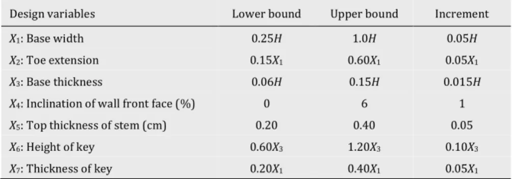
In the optimization problems generally should have three basic concepts, including the design space, the de-sign constraints and the objective function. The dimen-sions of CRW are the base width (X1), the toe extension (X2), the base thickness (X3), the inclination of the wall front face (X4), and the top thickness of the stem (X5) given in Fig 1(a). The dimensions of CRWK given in Fig. 2(a) which are the base width (X1), the toe extension (X2), the base thickness (X3), the inclination of the wall front face (X4), and the top thickness of the stem (X5), the height of key (X6) and the thickness of key (X7) were se-lected as the discrete design variables. To determinate of the lower-the upper bounds for the discrete design vari-ables, wall dimensions suggested in the provisions of Building Code Requirements for Structural Concrete (ACI 318-08, 2008) and LRFD Bridge Design Specifica-tions (AASHTO, 2010) were employed. The lower-the upper bounds of the discrete design variables with incre-ments have been tabulated in Table 1.
The wall designs obtained by using different values of the design variables given in Table 1 must provide these basic four rules for the external stability of the wall: (i) Safety factor of sliding of the wall must be greater than its minimum acceptable value, (ii) Safety factor of over-turning of the wall must be greater than its minimum al-lowable value, (iii) The pressure transferred from the base to the soil must be smaller than the ultimate bear-ing capacity of the soil, (iv) The eccentricity of resultant force at the base surface must be within in the core not to occur tension stress. Therefore, these rules were de-fined as design constraints for having values of minimum and maximum safety factors. The minimum safety fac-tors values of sliding, overturning and bearing capacity have been taken as Fs (s, min) = 1.50, Fs (o, min) = 1.50,
maximum safety factors (Fs (s, max), Fs (o, max), Fs (bc,
max)) whose changing values depend on soil properties were considered with the aim of obtaining more eco-nomical design. Besides, the eccentricity control in base
width constraint and geometric design constraints due to the wall dimensions were taken into consideration too in the optimization analyses. Normalized expressions of all design constraints are designated in Table 2.
Table 1. Design variables and limit bounds for CRW and CRWK.
Design variables Lower bound Upper bound Increment
X1: Base width 0.25H 1.0H 0.05H
X2: Toe extension 0.15X1 0.60X1 0.05X1
X3: Base thickness 0.06H 0.15H 0.015H
X4: Inclination of wall front face (%) 0 6 1
X5: Top thickness of stem (cm) 0.20 0.40 0.05
X6: Height of key 0.60X3 1.20X3 0.10X3
X7: Thickness of key 0.20X1 0.40X1 0.05X1
Table 2. Design constraints.
Design constraints Normalized expression
The sliding safety factor lower bound 𝑔𝑥(1) = 1 − 𝐹𝑠(𝑠)/𝐹𝑠(𝑠, min)
The sliding safety factor upper bound 𝑔𝑥(2) = 𝐹𝑠(𝑠)/𝐹𝑠(𝑠, max) − 1
The overturning safety factor lower bound 𝑔𝑥(3) = 1 − 𝐹𝑠(𝑜)/𝐹𝑠(𝑜, min)
The overturning safety factor upper bound 𝑔𝑥(4) = 𝐹𝑠(𝑜)/𝐹𝑠(𝑜, max) − 1
The bearing capacity safety factor lower bound 𝑔𝑥(5) = 1 − 𝐹𝑠(𝑏𝑐)/𝐹𝑠(𝑏𝑐, min)
The bearing capacity safety factor upper bound 𝑔𝑥(6) = 𝐹𝑠(𝑏𝑐)/𝐹𝑠(𝑏𝑐, max) − 1
The eccentricity constraint 𝑔𝑥(7) = 𝑋1/(6𝑒)
The geometric constraint 1 𝑔𝑥(8) = 𝑋5/(𝐻𝑋4+ 𝑋5) −1
The geometric constraint 2 𝑔𝑥(9) = (𝑋2+ 𝐻𝑋4+ 𝑋5)/𝑋1/−1
In this paper, the objective function of the optimiza-tion problem taken as concrete weight of CRW and CRWK. Wall weights of CRW and CRWK have been com-pared for different soil conditions. The mathematical ex-pressions of the objective formulation for CRW and CRWK are given Eqs. (14) and (15), respectively.
𝑓min= 𝑊1+ 𝑊2+ 𝑊3 (14)
𝑓min= 𝑊1+ 𝑊2+ 𝑊3+ 𝑊6 (15)
2.3. Artificial bee colony algorithm
The artificial bee colony algorithm (ABC) suggested by Karaboga (2005) is one of the metaheuristic optimization algorithms. It is inspired by swarm intelligence that is ef-fective interpersonal communication for surviving as a swarm in nature and having basic life needs such as nutri-tion, defense and migration. General concepts and rithm steps have given for the artificial bee colony algo-rithm based on bees' nutritional processes and behaviour in this chapter. Bees tried to find the best food source in the algorithm are divided into three groups; as the employed bees, the onlooker bees and the scout bees. The employed bees seek food source vicinity of the hive and evaluate the quality of a found food source. If this quality is better than
the previously found quality of the food source, the loca-tion of the food source is kept in their mind. The onlooker bees observe the returned employed bees that dance to share the information like the amount of nectar, quality, and location about the found food source. Factors like the type of dance or time of dancing are influential in selecting which food source is worth to prefer by the onlooker bees. When the food sources are consumed, the process of the employed bee and the onlooker bee is fulfilled. The ran-dom seeking of the scout bee commences for the possible food sources around the hive. The scout bee that finds a food source turns into an employed bee. Only one scout bee is allowed, and the number of employed bees is equal to the number of food sources in the algorithm.
In this optimization problem of the wall design, de-signs of CRW and CRWK with the changeable values of design variables correspond to food sources, and the quality of the food sources are the weights of the wall. The main steps of the ABC algorithm for the optimum de-sign of CRW and CRWK are as follows:
Step 1: The ABC algorithm parameters which are the number of employed bees (NEB), the number of on-looker bees (NOB), the number of the food source (NFS), the number of maximum iteration (maxiter), and limit (Akay and Karaboga, 2012) are defined and initial food source areas are formed by using Eq. (16).
𝑥𝑖𝑗= 𝑥𝑗min+ rand(0,1)(𝑥𝑗max− 𝑥𝑗min)
(𝑖 = 1, … , 𝑁𝐹𝑆, 𝑗 = 1, … , 𝑁) (16) Here, N is the total number of design variables. In this study, N has been taken 5 and 7 for designs of CRW and CRWK, respectively. Rand (0,1) means a random number between 0 and 1. xjmin and xjmax are given as the lower and
the upper bounds of the jth design parameter, respec-tively. The food matrix (FM) corresponding the design space is formed by using values of design variables given in Table 1 and Eq. (16). For each row of FM, which states wall designs, values of the objective function are calcu-lated.
Step 2: The employed bees determine a new food source and evaluate its quality. In determining a new food source which is neighbor of its current food source Eq.17 is used.
𝑖𝑗= {
𝑥𝑖𝑗+ Ø𝑖𝑗(𝑥𝑖𝑗− 𝑥𝑘𝑗), rand(0,1) < 𝑀𝑅 𝑥𝑖𝑗, rand(0,1) ≥ 𝑀𝑅
(Ø𝑖𝑗 = [−1,1]) (17)
Here, xij means the jth design variable randomly
se-lected of the ith food source and k is a randomly chosen value between 1 and NFS. The modification rate, MR, is a control parameter for use in checking a new source is de-veloped or not. The value of MR has been suggested to be between 0.30-0.80 (Akay and Karaboga, 2012). Fitness value for the appropriate new food source (ij) is
calcu-lated by using Eq. (18). fitness𝑖= {
1/(1 + 𝑓𝑖), 𝑓𝑖≥ 0
1 + abs(𝑓𝑖), 𝑓𝑖< 0 (18)
Here, fi is the objective function value of the new food
source. The selection process is performed between xi
and vi by using Deb's Rules (Deb, 2000) which consider
constraint violations of the obtained wall designs (Karaboga and Akay, 2011). If the penalty value of the new wall design is better than the worst penalty value one in mind, the worst wall design replaced with the new wall design. Otherwise, the worst one remains in mind. Step 3: All employed bees fulfil their seeking in the vicin-ity of the hive for the food sources and keep in their mind the information about them. In the algorithm, it means new wall designs obtained. Employed bees share infor-mation about the food sources like the amount of nectar and location of the food sources on the dance area. To give an idea to the onlooker bees is determined proba-bility values used in a probabilistic selection based on the information of the food sources. The onlooker bees evaluate the transferred information in proportion the calculated values of the fitness and constraint violations of the food sources. Probability of selection of the food source by the onlooker bees is defined in Eq. (19). 𝑝𝑖=
fitness𝑖
∑𝑁𝐹𝑆𝑗=1fitness𝑗 (19)
Step 4: The onlooker bees select the food source area us-ing the information provided by the employed bees in this step. If the produced random number within the range [0,1] is greater than the pi (Eq. (19)), the onlooker
bees produce a new food source like the employed bees by using Eq. (17). The new food source and the old food source are compared, and then the better one is selected by using Deb's rules. This process continues until all on-looker bees complete their search for the food sources. Step 5: It is checked whether the nectar in a food source is exhausted or not when the employed and the onlooker bees complete the cycles. After abandoned food sources are determined by using the limit parameter, scout bee initializes the searching for a new food source by using Eq. (16). This cycle continues until the current iteration number reaches the maximum iteration number, and then the algorithm terminates.
3. Optimization Analyses and Results
The optimum weights of CRW design given in Fig. 1 and CRWK design given in Fig. 2 were obtained by using the ABC algorithm. In the optimization analyses, sixteen variable soil conditions presented in Table 3 which in-clude two different values for the cohesion of foundation soil, two different values for the angle internal friction of the foundation soil, and four different values for the an-gle of internal friction of backfill soil were taken into con-sideration as example wall designs. Except for the three above mentioned soil parameters, the other input pa-rameters have been taken the same for all example wall designs.
Initial food sources were formed by using Eq. (16) for the design variables demonstrated in Table 1. The values of objective functions by using Eqs. (14) or (15) and pen-alty values by using design constraints given in Table 2 have been calculated for the wall designs. The ABC algo-rithm by continuing iterations and cycles achieved the optimum wall design among all possible wall designs, which has the minimum penalty value with the mini-mum wall weight for current soil condition.
In this study, the algorithm parameters of modifica-tion rate, populamodifica-tion size, number of the food source, limit and number of maximum iterations were taken as 0.40, 30, 15, NFSxN and 5000, respectively. For each soil condition, the algorithm has been operated in 500 times, by the number of maximum iterations and it also has been observed that the more minimum wall weight can-not be obtained anymore with continuing analysis of the cycles. The optimum wall weights are demonstrated in Fig. 3 for the various soil conditions.
Fig. 3 illustrates that the optimum wall weights de-crease with the increasing the angle of internal friction of the backfill soil and the cohesion of the foundation soil for all angle of internal friction of the foundation soil (Øbs). The feasible wall the feasible wall design satisfied
the design constraints was attained only for CRWK de-sign in the soil condition Øbs=20-35°, Øfs=20° and cfs=50
kPa. The CRW weight was smaller than the CRWK weight when the values of the cohesion of the foundation soil
and the angle of internal friction of the backfill soil were the minima (Øbs=20°, Øfs=30°and cfs=50kPa). There is no
conclusion that CRWK designs are less costly than CRW designs for other soil conditions.
Table 3. Parameters of example wall designs.
Input parameter Unit Symbol Value
Height of stem m H 6
Surcharge load kPa q 20
Backfill slope ° β 10
Depth of foundation m D 0.50
Unit weight of foundation soil kN/m3 γfs 19
Unit weight of backfill soil kN/m3 γbs 18
Unit weight of concrete kN/m3 γc 25
Cohesion of backfill soil kPa cbs 0
Cohesion of foundation soil Case 1 kPa cfs 50
Case 2 kPa cfs 100
Internal friction angle of foundation soil Case 1 ° Øfs 20
Case 2 ° Øfs 30
Internal friction angle of backfill soil
Case 1 ° Øbs 20
Case 2 ° Øbs 25
Case 3 ° Øbs 30
Case 4 ° Øbs 35
Fig. 3. Optimum wall weights for the various soil conditions.
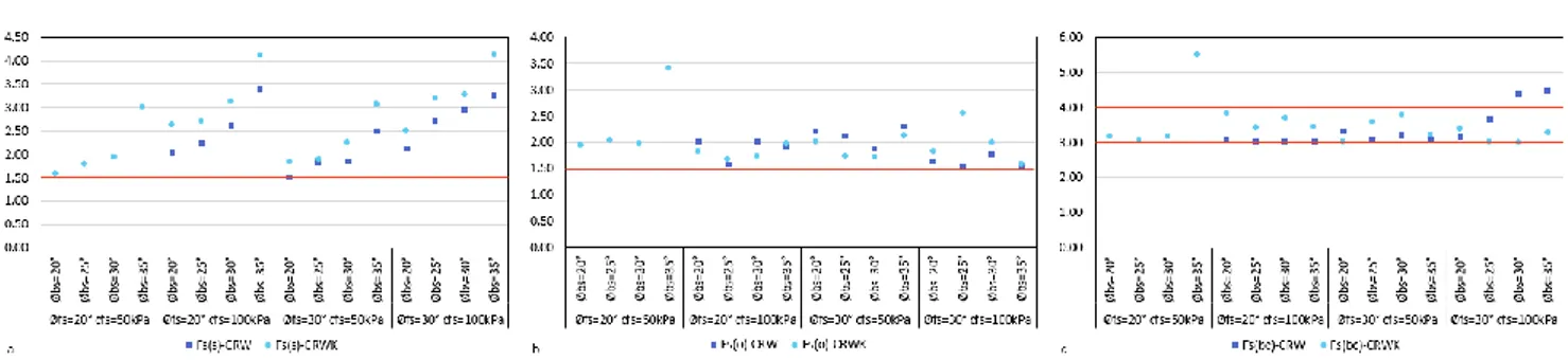
In the investigation of the optimum wall designs, lower-upper bounds of the safety factors have been se-lected to obtain the safe and economical design. Safety factors of sliding, overturning and bearing capacity, for wall design examples are shown in Fig. 4. The lower (Fs
(s, min), Fs (o, min), Fs (bc, min)) and the upper (Fs (s,
max), Fs (o, max), Fs (bc, max)) bounds of safety factors
for different soil conditions have been demonstrated at the same figure with the red lines.
It is evident from Fig. 4 while obtained optimum wall designs were satisfied with the lower bounds of safety factors.
Fig. 4. Safety factors of example wall designs: a) sliding; b) overturning; c) bearing capacity.
4. Conclusions
In this study, the optimum designs of concrete canti-lever retaining walls have been investigated using the ar-tificial bee colony algorithm, an effective optimization technique that has been widely applied to engineering problems. The wall dimensions of concrete cantilever re-taining wall (CRW) and the concrete cantilever rere-taining wall with the key (CRWK) satisfied stability conditions have been attained to find the minimum wall weight. Ac-cording to the result of the optimization analysis, the costs of CRW and CRWK designs have growth when the angle of internal friction of the foundation soil is smaller than 25°. CRWK design is more economical than CRW de-sign just for poor foundation soil. Adding a key to the concrete cantilever retaining wall is insignificant in terms of obtaining the more economical wall designs for quality foundation soil. Consequently, it is observed that the artificial bee colony algorithm can be effectually used in obtaining the optimum concrete retaining wall de-signs.
REFERENCES
ACI 318-08 (2008). ACI Committee 318, Building Code Requirements for Structural Concrete. American Concrete Institute.
AASHTO (2010). American Association of State Highway and Trans-portation Officials LRFD Bridge Design Specifications.
Akay B, Karaboga D (2012). A modified artificial bee colony algorithm for real-parameter optimization. Information Sciences, 192, 120-142.
Camp C, Akin A (2012). Design of retaining walls using big bang–big crunch optimization. Journal of Structural Engineering, 138(3), 438-448.
Das BM (2016). Principles of foundation engineering. Cengage Learn-ing, Eighth Edition.
Deb K (2000). An efficient constraint handling method for genetic al-gorithms. Computer Methods in Applied Mechanics and Engineering, 186 (2-4), 311-338.
Dorigo M, Gambardella LM (1997). Ant colonies for the travelling sales-man problem. Biosystems, 43(2), 73-81.
Gandomi, AH, Kashani AR, Roke DA, Mousavi M (2015). Optimization of retaining wall design using recent swarm intelligence techniques. Engineering Structures, 103, 72-84.
Geem ZW, Kim JH, Loganathan GV (2001). A new heuristic optimization algorithm: harmony search. Simulation, 76(2), 60-68.
Goldberg DE (1989). Genetic algorithms and Walsh functions: part I, a gentle introduction. Complex Systems, 3 (2), 129-152.
Karaboga D (2005). An idea based on honeybee swarm form numerical optimization, Technical Report TR06, Erciyes University, Turkey. Karaboga D, Akay B (2011). A modified artificial bee colony (ABC)
al-gorithm for constrained optimization problems. Applied Soft Com-puting, 11(3), 3021-3031.
Kennedy J, Eberhart R (1995). Particle swarm optimization. Proceed-ings of ICNN'95-International Conference on Neural Networks, 1942-1948.
Meyerhof GG (1963). Some recent research on the bearing capacity of foundations. Canadian Geotechnical Journal, 1(1), 16–26.
Rajabioun R (2011). Cuckoo optimization algorithm. Applied Soft Com-puting, 11(8), 5508-5518.
Rankine W (1857). Earth Pressure Theory. Phil. Trans. of the Royal Soc. Sarıbaş A, Erbatur F (1996). Optimization and sensitivity of retaining structures. Journal of Geotechnical Engineering, 122(8), 649-656. Temür R, Bekdaş G (2016). Teaching learning-based optimization for
design of cantilever retaining walls. Structural Engineering and Me-chanics, 57(4), 763–783.
Uray E, Çarbaş S, Erkan İH, Tan Ö (2019). Parametric investigation for discrete optimal design of a cantilever retaining wall. Challenge Journal of Structural Mechanics, 5(3), 108-120.
Yang XS (2009). Firefly algorithms for multimodal optimization. Inter-national Symposium on Stochastic Algorithms, 169-178.