Proceedings of the ASME 2017 15th International Conference on Nanochannels, Microchannels, and Minichannels ICNMM 2017 August 27-31, 2017, Cambridge, MA, USA
ICNMM2017-5537
MODELING OF EVAPORATION FROM A SESSILE CONSTANT SHAPE DROPLET
Yi ˘git Akkus¸
ASELSAN A.S¸ ., Yenimahalle Ankara 06172 TURKEY Email: [email protected]
Barbaros C¸ etin∗
Mechanical Engineering Department ˙I.D. Bilkent University
Ankara 06800 TURKEY Email: [email protected]
Zafer Dursunkaya Dept. Mechanical Engineering Middle East Technical University
Ankara 06800 TURKEY Email: [email protected]
ABSTRACT
In this study, a computational model for the evaporation from a sessile liquid droplet fed from the center to keep the diam-eter of the droplet constant is presented. The continuity, momen-tum and energy equations are solved with temperature depen-dent thermo-physical properties using COMSOL Multi-physics. At the surface of the droplet, convective heat and evaporative mass fluxes are assigned. Since the flow field is affected by evap-orative flux, an iterative scheme is built and the computation is automated using COMSOL-MATLAB interface. Correlations are implemented to predict the convective heat transfer coefficients and evaporative flux. Three different wall temperatures are used in simulations. The results show that the flow inside the droplet is dominated by buoyancy when the effect of the thermo-capillarity is neglected. The resulting flow generates a circulation pattern emerging from the entrance to the apex, along the surface of the droplet to the bottom heated wall and back to the entrance.
NOMENCLATURE Symbol A surface area [ m2] cp specific heat [ J/kg · K] g gravitational acceleration [ m/s2] hf g enthalpy of vaporization [ J/kg]
hm convective mass transfer coefficient [ m/s]
hnc natural convection heat transfer coefficient [ W/m2· K]
k thermal conductivity [ W/m · K] Le Lewis number
n unit normal vector NuD Nusselt number p pressure [ Pa] Pr Prandtl number RaD Rayleigh number r radius [ m] T temperature [ K] u velocity vector [ m/s]
θ polar angle measured from apex [◦] µ viscosity [ kg/m · s]
ρ density [ kg/m3] ¯¯τ stress tensor [ Pa] Subscript evap evaporation in inlet l liquid out outlet s free surface sat saturated vap vapor w wall ∞ ambient
INTRODUCTION
Droplet evaporation is a process encountered in nature and technological applications; and evaporation of sessile droplets is a widely studied topic in the literature [1–6]. Due to high en-ergy removal capacity of phase change, a substantial amount of heat can be removed by evaporation which makes the droplet evaporation a useful tool for cooling applications. A reliable and continuous cooling requires the droplets to endure without be-ing entirely consumed durbe-ing the coolbe-ing process. Feedbe-ing of the droplet from the substrate enables the droplet to maintain its shape during cooling.
In the literature, there exists many studies which report the distribution of evaporative heat flux or surface temperature of droplets [6–10]. Evaporation flux from a spherical droplet (with 90◦contact angle) is predicted as uniform along the interface fol-lowing a correlation which is primarily based on the contact an-gle of the drying droplet [7]. In these studies, however, droplets are not fed and their shapes continuously change during evapora-tion process. In a recent study, evaporaevapora-tion from a sessile droplet, which preserves its shape by liquid feeding, is experimentally investigated to capture the temperature distribution and corre-sponding evaporative mass flux at the interface [11]. The droplet is assumed as perfect half sphere with 90◦contact angle. In this experimental work, the temperature inside the droplet was mea-sured at discrete locations, and the flow field inside the droplet was deduced in accordance with the temperature readings. To understand the detailed physics inside the droplet, computational modeling offers a significant advantage.
In the present study, a computational model to predict the temperature and flow field inside a sessile spherical droplet (with 90◦contact angle) which is continuously fed by liquid injection is developed to explore the flow and temperature fields inside the droplet. In the modeling of the current problem, the bound-ary conditions at the droplet surface are functions of the surface temperature distribution, which is unknown a priori. Therefore, the present work applies an iterative computational scheme in which boundary conditions are updated using the computed sur-face temperature distribution.
THEORY
Steady-state evaporation from a sessile water droplet lying on a heated wall is considered in this study. Shape of the evapo-rating droplet is selected as a perfect half sphere which simplifies the problem enabling the implementation of an 2-D axisymmet-ric model. A 3-D representation of the geometry can be seen in Figure 1–(a). Spherical geometry of the droplet is preserved by continuous liquid feeding from a concentric inner half sphere. Problem domain for the 2-D axisymmetric model is given in Fig-ure 1–(b). The steady-state conservation of mass, momentum and energy equations can be written as:
(a) 3-D REPRESENTATION OF THE GEOMETRY
(b) PROBLEM DOMAIN
FIGURE 1. PROBLEM GEOMETRY
∇ · (ρlu) = 0 (1)
ρl(u · ∇)u = −∇pl+ µl∇2u + ρlg (2)
ρlcp,l(u · ∇T ) = ∇ · (kl∇T ) + ¯¯τ : ∇u (3)
2-D axisymmetric model ensures the symmetry boundary condition along the centerline of the droplet. At the wall, no slip and constant temperature boundary conditions are defined. Inlet boundary of the domain where continuous water feeding is supplied, has the same temperature with the wall. The velocity of the water at the inlet, on the other hand, is assumed uniform along the surface. The distributions of liquid velocity, natural convection coefficient and evaporative mass flux at the liquid-gas interface are unknown a priori. Associated boundary conditions
are summarized as follows: ∂θu = 0, ∂θT = 0 at θ = 0 (4) u = 0, T = Tw at θ = π 2 (5) u = ¯uin, T = Tw at r = rin (6) u = uout, −k∂rT= hnc(T − T∞) + ˙m 00 evaphf g at r = rout (7)
The difference between the saturated vapor density at the in-terface and the vapor density of the ambient is multiplied by a proper mass transfer coefficient to model the evaporative mass flux at the droplet surface [12]. Saturated vapor density distri-bution is calculated as the function of the interface temperature distribution. The vapor density of the ambient, on the other hand, is evaluated based on the relative humidity of the ambient. The value of the relative humidity, which is taken as 0.4, is aimed to be in the comfort zone.
˙
m00evap= hm(ρvap,sat(Ts) − ρvap,∞) (8)
The mass transfer coefficient is calculated using the analogy be-tween heat and mass transfer [13]:
hm= hnc/(ρaircp,airLe2/3) (9)
hncdepends on the dimensionless NuD, evaluated at the interface
as follows:
hnc= NuDkair/(2rout) (10)
Nu is calculated according to the correlation recommended by [14] for immersed spheres in a surrounding fluid:
NuD= 2 +
0.589Ra1/4D
[1 + (0.469/Pr)9/16]4/9 (11)
COMPUTATIONAL MODELING
The governing equations are solved numerically using COMSOL Multi-physics software. The radii of the droplet and the liquid injection region are selected as 2.5 mm and 0.1 mm, respectively. The temperature of the heated wall is assumed to be constant. Moreover, the feeding water is assumed to be in thermal equilibrium with the heated wall yielding the same tem-perature with the wall. Three different wall and feeding water
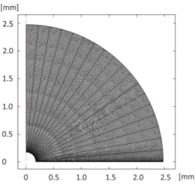
FIGURE 2. MESH CONFIGURATION
temperatures are used; 40◦C, 55◦C and 70◦C. Ambient temper-ature is 25◦C for all three cases. To assign varying evaporating flux on the surface, the solution domain is divided into angu-lar strips. Meshing is performed by COMSOL which results in 14799 quadrilateral and 296 triangular elements. The mesh dis-tribution is given in Figure 2. Mesh independence is tested us-ing three different sets of grids. The performance of each mesh is tested based on the volume average temperature of the entire droplet. Results show that simulations predict almost identical results for all tested mesh configurations.
The primary challenge in the modeling of the droplet evap-oration is that boundary conditions at the liquid-gas interface are functions of the interface temperature which is unknown a priori. Consequently, distributions of liquid velocity, natural convection coefficient and evaporative mass flux cannot be directly defined at the interface. The current study proposes an iterative compu-tational scheme which enables the simultaneous solution of the mass, momentum and energy equations with the temperature de-pendent thermo-physical properties. The computational steps are as follows:
Step-0: Initialization: Initial estimates of the boundary condi-tions at the inlet and outlet of the domain, i.e. liquid feeding surface (r = rin) and liquid-gas interface (r = rout) of the droplet,
are made. A uniform velocity distribution is assumed at the inlet and this average value is calculated based on the initial guess of liquid feeding rate, ( ˙mtotevap)o:
¯ uin=
( ˙mtotevap)o
Ainρl(Tw)
(12)
It should be noted that the velocity at the inlet is assumed to be perpendicular to the surface. In other words, tangential compo-nent of the velocity at the inlet is neglected. Distribution of the
velocity at the liquid-gas interface, on the other hand, is iterated and uniform distribution is only assumed as an initial estimate,
¯
uoout, which is calculated based on the ratio of the surface areas:
¯ uoout= ¯uin
Ain
Aout
(13)
Step-1: Simultaneous solution of governing equations: Con-tinuity, momentum and energy equations with the correspond-ing boundary conditions are solved uscorrespond-ing the FEM solver of COMSOL software with temperature dependent thermo-physical properties.
Step-2: Calculations of evaporative mass flux and heat trans-fer coefficient: Evaporative mass flux, ˙m00evap(θ ), and natural convection heat transfer coefficient, hnc(θ ), are estimated based
on the distribution of the interface temperature, Ts, calculated in
Step-1, where properties of air are evaluated at the ambient tem-perature, T∞.
Step-3: Calculation of velocity distribution at the interface: Normal component of the interface velocity is updated using the distribution of evaporative mass flux evaluated in the previous step: uout· n = ˙ m00evap(θ ) ρl(Ts(θ )) . (14)
The updated interface velocity distribution is stored to be used in the next iterative step.
The entire procedure is automated via COMSOL-MATLAB interface. The velocity at the outlet is also assumed to be perpen-dicular to the surface. Similar to the outlet velocity, distribution of the natural convection heat transfer coefficient is updated at each iteration. Initially, surface temperatures and corresponding heat transfer coefficients are assumed to be constant and uniform, which are updated as functions of surface location (θ ) during it-erations.
RESULTS AND DISCUSSION
The effect of the wall temperature is studied in three cases (Case-1: Tw = 40◦C, Case-2: 55◦C, Case-3: 70◦C). The
tem-perature and flow field together with the temtem-perature and flux distributions on the surface are obtained.
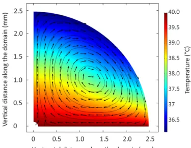
Figure 3 shows the results for Tw= 40◦C. The hot liquid
entering the domain moves to the apex of the droplet. In the close proximity of interface, the liquid cools due to heat trans-fer to ambient via convection and evaporation, and temperatures continue to drop as the colder fluid moves along the interface to-wards the heated surface under the effect of favorable buoyancy.
(a) TEMPERATURE FIELD, STREAMLINES AND VELOCITY VECTORS
(b) TEMPERATURE AND HEAT FLUX ON THE SURFACE
FIGURE 3. SIMULATION RESULTS (Tw= 40◦C)
Near the wall, particles are heated due to the heat transfer from the wall, and move towards the inlet where hot liquid enters the domain. The two hot liquid streams merge and move to the apex of the droplet resulting a clockwise vortex pattern. Distribution of the heat flux and temperature at the liquid-gas interface is il-lustrated in 3–(b). Both the heat flux and surface temperature have similar behavior, remaining almost constant near the apex of the droplet. Both the heat flux and temperature increase grad-ually, and a rapid increase is observed near the wall such that the surface temperature matches the wall temperature, and the surface heat flux reaches its maximum value at the contact line.
Figure 4 shows the results for Tw = 55◦C. Although the
predicted flow pattern is similar, temperature distribution in the droplet is quite different than the previous case. The
simula-(a) TEMPERATURE FIELD, STREAMLINES AND VELOCITY VECTORS
(b) TEMPERATURE AND HEAT FLUX ON THE SURFACE
FIGURE 4. SIMULATION RESULTS (Tw= 55◦C)
tion yields an intermediate cooler zone near the interface. This temperature well is more recognizable at approximately 60◦ po-lar angle. Distribution pattern of the surface heat flux is simipo-lar to the surface temperature, yielding a minima for the heat flux around the same location.
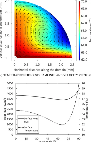
Figure 5 shows the results for Tw= 70◦C. The flow pattern
is similar to the previous cases. The temperature and heat flux distributions on the surface are similar to Case-2, but the location of the minimum is shifted to the wall side as seen in Fig. 5–(b).
Simulation results show that temperature distribution pat-terns inside the droplet is different for the low (40◦C) and rel-atively higher (55◦C, 70◦C) wall temperatures. The hot liquid migrating from bottom of the droplet starts to cool near the
in-(a) TEMPERATURE FIELD, STREAMLINES AND VELOCITY VECTORS
(b) TEMPERATURE AND HEAT FLUX ON THE SURFACE
FIGURE 5. SIMULATION RESULTS (Tw= 70◦C)
terface and moves to the bottom of the droplet cooling due to evaporation and heat transfer to surroundings. For the higher temperature cases, when the liquid approaches the wall, it expe-riences heating due to the conduction from the wall. These two adverse effects lead to the formation of a temperature minima on the surface.
The applicability of the assumptions and the validity of the evaporative mass flux calculation require further investigation. The assumption regarding the physical shape of the droplet also needs validation. Simulations reveal that liquid pressure at the top of the droplet is 24 Pa smaller than the one at the bottom of the droplet. Assuming a uniform distribution of pressure within the gas phase and negligible change in the surface tension, higher radius of curvature values are expected near the top of the droplet
given by Young-Laplace equation. Therefore, a flattening is ex-pected near the top region of the droplet which renders the ge-ometry of the problem and may lead to a flow pattern different than what is observed, albeit, only marginally. Another physi-cal phenomenon currently not included is the thermo-capillary effect. The change in the surface tension due to the temperature gradient may affect the flow pattern. Therefore, a more compre-hensive approach including Marangoni effect needs to be imple-mented in order to estimate the significance of thermo-capillarity on the flow field.
CONCLUSIONS
In the current study, evaporation from a sessile liquid droplet is modeled. The simulations show that the flow inside the droplet is dominated by buoyancy when the effect of the thermo-capillarity is neglected. The injected fluid remains at the core, isolated from the colder external atmosphere, resulting in an up-ward motion along the line of symmetry. Once near the surface, the cooling effect at the boundary results in a downward motion and a drop in surface temperature. Close to the heated wall, the surface temperature of the fluid is high, resulting in the charac-teristic minimum temperature observed at approximately 60◦and 65◦polar angles for the wall temperatures; 55◦C and 70◦C, re-spectively. This temperature minima, however, is not apparent in the lowest wall temperature case, 40◦C. For all cases, on the other hand, the resulting flow circulates from the entrance to the apex, along the surface to the bottom heated wall and back to the entrance, resulting a CW rotation. The implementation of the current computational model to predict the experimental results of the study by Mahmud and MacDonald [11] will be the content of future research.
ACKNOWLEDGMENT
Authors would like to acknowledge Dr. Brendan MacDon-ald for bringing this problem to the authors’ attention.
REFERENCES
[1] Kokalj, T., Cho, H., Jenko, M., and Lee, L., 2010. “Bio-logically inspired porous cooling membrane using arrayed-droplets evaporation”. Applied Physics Letters, 96(16), p. 163703.
[2] Talbot, E., Berson, A., Brown, P., and Bain, C., 2012. “Evaporation of picoliter droplets on surfaces with a range of wettabilities and thermal conductivities”. Physical Re-view E, 85(6), p. 061604.
[3] Smalyukh, I. I., Zribi, O. V., Butler, J. C., Lavrentovich, O. D., and Wong, G. C., 2006. “Structure and dynamics of liquid crystalline pattern formation in drying droplets of dna”. Physical review letters, 96(17), p. 177801.
[4] Sefiane, K., 2010. “On the formation of regular patterns from drying droplets and their potential use for bio-medical applications”. Journal of Bionic Engineering, 7, pp. S82– S93.
[5] Paria, S., Chaudhuri, R. G., and Jason, N. N., 2014. “Self-assembly of colloidal sulfur particles on a glass surface from evaporating sessile drops: influence of different salts”. New Journal of Chemistry, 38(12), pp. 5943–5951. [6] Deegan, R. D., Bakajin, O., Dupont, T. F., Huber, G.,
Nagel, S. R., and Witten, T. A., 1997. “Capillary flow as the cause of ring stains from dried liquid drops”. Nature, 389(6653), pp. 827–829.
[7] Hu, H., and Larson, R. G., 2002. “Evaporation of a sessile droplet on a substrate”. The Journal of Physical Chemistry B, 106(6), pp. 1334–1344.
[8] Dunn, G., Wilson, S., Duffy, B., David, S., and Sefiane, K., 2009. “The strong influence of substrate conductivity on droplet evaporation”. Journal of Fluid Mechanics, 623, pp. 329–351.
[9] Duan, F., and Ward, C., 2009. “Investigation of local evaporation flux and vapor-phase pressure at an evaporative droplet interface”. Langmuir, 25(13), pp. 7424–7431. [10] Duan, F., 2009. “Local evaporation flux affected by
thermo-capillary convection transition at an evaporating droplet”. Journal of Physics D: Applied Physics, 42(10), p. 102004. [11] Mahmud, M. A., and MacDonald, B. D., 2017. “Exper-imental investigation of interfacial energy transport in an evaporating sessile droplet for evaporative cooling applica-tions”. Phys. Rev. E, 95.
[12] Ruiz, O. E., and Black, W. Z., 2002. “Evaporation of water droplets placed on a heated horizontal surface”. J. Heat Transfer, 124.
[13] Incropera, F. P., and DeWitt, D. P., 1990. Fundamentals of Heat and Mass Transfer. John Wiley & Sons, New York. [14] Churchill, S. W., 2002. Free convection around immersed
bodies. in G. F. Hewitt, Exec. Ed., Heat Exchanger Design Handbook, Section 2.5.7, Begell House, New York.