Multichannel optical diode with unidirectional
diffraction relevant total transmission
Andriy E. Serebryannikov,1,* A. Ozgur Cakmak,2 and Ekmel Ozbay2
1Hamburg University of Technology, E-3, D-21071 Hamburg, Germany
2Department of Electrical and Electronics Engineering, Nanotechnology Research Center, Bilkent University, 06800 Ankara, Turkey
Abstract: We will show that broadband unidirectional optical transmission with a total transmission maximum inside the band can be obtained for linearly polarized incident waves in the nonsymmetric photonic crystal gratings made of isotropic linear materials at a fixed nonzero or zero angle of incidence. Being based on the merging of diffraction and dispersion effects, the basic physical mechanism studied exploits the transmission channels associated with higher orders, for which asymmetry in the coupling conditions at the two grating interfaces appears when spatial inversion symmetry is broken. Total transmission in one direction and zero transmission in the opposite direction can be obtained due to hybridization of Fabry-Perot type resonances with a diffraction anomaly that yields a diode-like operation regime. Single-beam deflection and two-beam splitting can be obtained, for which transmission can be (nearly) total, if the corrugated side is illuminated. In contrast to the previous studies, it is also shown that unidirectional transmission can appear only at a fixed frequency and only due to diffractions, when total transmission occurs at the noncorrugated-side illumination, being in agreement with the Lorentz Lemma.
©2012 Optical Society of America
OCIS codes: (050.1950) Diffraction gratings; (050.1960) Diffraction theory; (050.2230)
Fabry-Perot; (050.5298) Photonic crystals; (120.7000) Transmission
References and links
1. Z. Wang, Y. D. Chong, J. D. Joannopoulos, and M. Soljacić, “Reflection-free one-way edge modes in a gyromagnetic photonic crystal,” Phys. Rev. Lett. 100(1), 013905 (2008).
2. F. D. M. Haldane and S. Raghu, “Possible realization of directional optical waveguides in photonic crystals with broken time-reversal symmetry,” Phys. Rev. Lett. 100(1), 013904 (2008).
3. A. Figotin and I. Vitebskiy, “Electromagnetic unidirectionality and frozen modes in magnetic photonic crystals,” J. Magn. Magn. Mater. 300(1), 117–121 (2006).
4. C. He, X.-L. Chen, M.-H. Lu, X.-F. Li, W.-W. Wan, X.-S. Qian, R.-C. Yin, and Y.-F. Chen, “Tunable one-way cross-waveguide splitter based on gyromagnetic photonic crystal,” Appl. Phys. Lett. 96(11), 111111 (2010). 5. M. Scalora, J. P. Dowling, C. M. Bowden, and M. J. Bloemer, “The photonic band edge optical diode,” J. Appl.
Phys. 76(4), 2023–2025 (1994).
6. M. Soljacić, C. Luo, J. D. Joannopoulos, and S. Fan, “Nonlinear photonic crystal microdevices for optical integration,” Opt. Lett. 28(8), 637–639 (2003).
7. C. E. Rüter, K. G. Makris, R. El-Ganainy, D. N. Christodoulides, M. Segev, and D. Kip, “Observation of parity– time symmetry in optics,” Nat. Phys. 6(3), 192–195 (2010).
8. C. Menzel, C. Helgert, C. Rockstuhl, E.-B. Kley, A. Tünnermann, T. Pertsch, and F. Lederer, “Asymmetric transmission of linearly polarized light at optical metamaterilas,” Phys. Rev. Lett. 104(25), 253902 (2010). 9. J.-Y. Chen and L.-W. Chen, “Color separating with integrated photonic band-gap optical diodes: a numerical
study,” Opt. Express 14(22), 10733–10739 (2006).
10. G. Shvets, “Optical polarizer/isolator based on rectangular waveguide with helical grooves,” Appl. Phys. Lett.
89(14), 141127 (2006).
11. Z. Yu and S. Fan, “Complete optical isolation created by indirect interband photonic transitions,” Nat. Photonics 3(2), 91–94 (2009).
12. S. K. Ibrahim, S. Bhandare, D. Sandel, H. Zhang, and R. Noe, “Non-magnetic 30dB integrated opical isolator in III/Vmaterial,” Electron. Lett. 40(20), 1293–1294 (2004).
13. K. Inoue and K. Ohtaka, Eds., Photonic Crystals. Physics, Fabrication, and Applications (Springer, Berlin, 2004).
14. A. E. Serebryannikov, “One-way diffraction effects in photonic crystal gratings made of isotropic materials,” Phys. Rev. B 80(15), 155117 (2009).
15. A. O. Cakmak, E. Colak, A. E. Serebryannikov, and E. Ozbay, “Unidirectional transmission in photonic-crystal gratings at beam-type illumination,” Opt. Express 18(21), 22283–22298 (2010).
16. X.-F. Li, X. Ni, L. Feng, M.-H. Lu, C. He, and Y. F. Chen, “Tunable unidirectional sound propagation through a sonic-crystal-based acoustic diode,” Phys. Rev. Lett. 106(8), 084301 (2011).
17. C. Lu, X. Hu, H. Yang, and Q. Gong, “Ultrahigh-contrast and wideband nanoscale photonic crystal all-optical diode,” Opt. Lett. 36(23), 4668–4670 (2011).
18. K. Xiu-Bao, T. Wei, W. Zhan-Shan, W. Zhi-Guo, and C. Hong, “High efficiency one-way transmission by one-dimensional photonic crystals with graings on one side,” Chin. Phys. Lett. 27(7), 074204 (2010). 19. M. Beruete, A. E. Serebryannikov, V. Torres, M. Navarro-Cia, and M. Sorolla, “Toward compact
millimeter-wave diode in thin stacked hole array assisted by a dielectric grating,” Appl. Phys. Lett. 99(15), 154101 (2011).
20. S. Cakmakyapan, A. E. Serebryannikov, H. Caglayan, and E. Ozbay, “One-way transmission through the subwavelength slit in nonsymmetric metallic gratings,” Opt. Lett. 35(15), 2597–2599 (2010).
21. S. Cakmakyapan, H. Caglayan, A. E. Serebryannikov, and E. Ozbay, “Experimental validation of strong directional selectivity in nonsymmetric metallic gratings with a subwavelength slit,” Appl. Phys. Lett. 98(5), 051103 (2011).
22. R. Moussa, S. Foteinopoulou, L. Zhang, G. Tuttle, K. Guven, E. Ozbay, and C. M. Soukoulis, “Negative refraction and superlens behavior in a two-dimensional photonic crystal,” Phys. Rev. B 71(8), 085106 (2005). 23. A. E. Serebryannikov, A. Y. Petrov, and E. Ozbay, “Toward photonic crystal based spatial filters with wide
angle ranges of total transmission,” Appl. Phys. Lett. 94(18), 181101 (2009).
24. C. Luo, S. G. Johnson, J. D. Joannopoulos, and J. B. Pendry, “All-angle negative refraction without negative effective index,” Phys. Rev. B 65(20), 201104 (2002).
25. T. Magath and A. E. Serebryannikov, “Fast iterative, coupled-integral-equation technique for inhomogeneous profiled and periodic slabs,” J. Opt. Soc. Am. A 22(11), 2405–2418 (2005).
26. See, www.cst.com.
27. A. E. Serebryannikov and E. Ozbay, “Unidirectional transmission in non-symmetric gratings containing metallic layers,” Opt. Express 17(16), 13335–13345 (2009).
28. J. B. Pendry, A. J. Holden, W. J. Stewart, and I. Youngs, “Extremely low frequency plasmons in metallic mesostructures,” Phys. Rev. Lett. 76(25), 4773–4776 (1996).
29. B. T. Schwartz and R. Piestun, “Total external reflection from metamaterial with ultralow refraction index,” J. Opt. Soc. Am. B 20(12), 2448–2453 (2003).
30. D. Schurig and D. R. Smith, “Spatial filtering using media with indefinite permittivity and permeability tensors,” Appl. Phys. Lett. 82(14), 2215–2217 (2003).
31. J. A. Kong, Electromagnetic Wave Theory (EMW Publishing, Cambridge, MA, USA, 2005).
1. Introduction
Diode-like optical transmission is usually associated with the use of anisotropic [1–4] or nonlinear [5,6] materials. Single-channel diffraction-free unidirectional transmission is expected to require the simultaneous breaking of time-reversal and spatial inversion symmetries [7]. For example, strongly pronounced unidirectional transmission has been observed in a stack of two two-dimensional photonic crystals (PCs) that are made of gyromagnetic materials [1,4]. On the other hand, searching for asymmetric reciprocal (in sense of the Lorentz Lemma) transmission, i.e., that obtainable without breaking time-reversal symmetry has been a focus of interest for a long time. Chiral structures are known to enable a well pronounced asymmetry in transmission [8] and isolation for certain polarization states [9,10]. Complete optical isolation can also be achieved dynamically due to the temporal modulation of the refractive index in a linear photonic system [11]. Nonmagnetic optical isolators can be obtained in the structures that contain two modulators, in which a desired phase shift for co- and counter-propagating waves is achieved due to temporal modulation of bias voltages [12].
On the other hand, PCs made of isotropic linear materials show a rich variety of dispersion types, which are associated with the intriguing phenomena like negative refraction, focusing, superprism, and collimation [13]. Recently, it has been suggested to utilize the combination of some of the dispersion features with the effect of curvilinear interface(s) of the PC in order to obtain one-way transmission regimes [14]. In particular, it has been demonstrated that strong directional selectivity, i.e., strong forward-to-backward transmission contrast can be obtained in the gratings based on square-lattice dielectric PCs, whose spatial
inversion symmetry is broken due to that the corrugations are either different at the two sides, or placed at one of the sides only. It needs a proper combination of the umklapp scattering relevant asymmetry in coupling and dispersion, creating new transmission channels that might be open in a one-way manner. For this mechanism, the forward transmission, i.e., from half space I, which is bounded by the corrugated interface, to half space II, which is bounded by the noncorrugated interface, can be significant (transmittance T→< and reflectance 1
1
R→≤ ), while backward transmission is blocked (T← 0
= and R←= ) at the same angle of 1 incidence, θ θ→ θ←
= = , which is measured in the same, e.g., clockwise direction with respect to the normal to the incidence side. Hence, an extremely strong asymmetry in transmission can be achieved.
According to [14], for this diode-like asymmetric transmission mechanism, the dispersion in the PC has to ensure that the specular (zero) order is not coupled to a Floquet-Bloch (FB) wave of the PC. This is a key condition that is required for its existence. In turn, umklapp scattering is responsible for the multichannel nature of this mechanism. At least one higher order must propagate in air and must be coupled to a FB wave, but only if the corrugated side is illuminated. Hence, at least two propagation channels are required to be open in air half spaces, each being connected with a certain diffraction order. At the same time, all the orders (zero and higher) are uncoupled at the noncorrugated-side illumination. In terms of the nth-order diffraction efficiencies in transmission (partial transmittances), tn
→
and tn
←
, a nonsymmetric dielectric grating allows one obtaining a partially asymmetric transmission, because tn tn
→ ←
≠ at n >0 (asymmetric component) and t0 t0
→ ←
= (symmetric component) at
θ θ→ θ←
= = . However, wideband suppression of the symmetric component cannot be achieved in the general case. Using a PC instead of a dielectric, one can obtain extreme asymmetry in transmission, i.e., unidirectionality with t0 t0 0
→ ←
= = , while tn 0
←
= for all n in wide ranges of variation in frequency and angle of incidence. Thus, T← =0, but T → >0 due to extreme conversion of the incident wave energy into that of higher diffraction orders (n >0), which are efficiently coupled to a FB wave. For the diffraction inspired mechanism of asymmetric transmission, all the waves keep linear polarization.
The first experimental results have been obtained to validate this mechanism in PC gratings in the microwave regime [15]. Later, the same idea has been utilized in sonic crystals at θ ≠0, for which the experimental validation has also been done [16]. Recently, the structures with the diffraction relevant asymmetric transmission have been reported that are designed to operate at optical frequencies [17]. In fact, it does not matter whether one-dimensional, two-one-dimensional, or three-dimensional PC is taken to obtain a PC grating. For example, similar transmission features have been found in the structures that comprise a slab of one-dimensional PC and a dielectric grating placed at one of the interfaces [18]. Unidirectional transmission that exploits the combination of the dispersion and diffraction effects has been demonstrated in the compact (less than one free-space wavelength thick) structure that is based on the stacked hole arrays with one-side corrugations [19]. Similar unidirectional transmission in the beaming regime has been obtained in the nonsymmetric gratings with a single subwavelength slit, where it is connected with the asymmetry in excitation of spoof surface plasmons at the input and exit interfaces [20,21]. The exactly diode regime, i.e., that with total transmission in one direction has not been reported yet.
In this paper, we will show that total unidirectional diode-like transmission, with T →= 1 and T← =0, can be obtained in the nonsymmetric PC gratings owing to the umklapp scattering relevant coupling, for s-polarized incident light at the plane-wave approximation. It can occur at some angles of incidence and frequencies taken from a wide range, for which
1
T →≤ and T← =0, at least in case of (near-)square-shaped isofrequency dispersion contours (IFCs) like those known from the studies of negative refraction, imaging and spatial filtering in PCs [22–24]. A different number of the propagating beams can be involved in the
transmission also at T→ 1
= and T ← 0
= , leading to various regimes of asymmetric transmission, e.g., two-beam unidirectional splitting and single-beam unidirectional deflection. In contrast with the earlier studies, similar regimes but with T←= and 1 T→ =0 will also be demonstrated at some frequencies, at which zero order is coupled to a FB wave at the input side, but zero-order transmission is suppressed in the exit half space due to the peculiar diffractions. Consideration is restricted here to the square-lattice PCs composed of circular dielectric rods. The diffraction angles, φn→
and φn←
, are measured in the counter-clockwise direction with respect to the normal to the incidence side for the reflected waves, and in the clockwise direction with respect to the normal to the exit side for the transmitted waves. Diffraction results have been obtained by using Coupled Integral Equation Technique [25]. CST Microwave Studio [26] has been used for the calculations of the dispersion of FB waves.
2. Dispersion and coupling scenarios
First, let us review the coupling scenarios which are associated with the different coupling conditions at the interfaces of a nonsymmetric grating. The condition of the uncoupled zero order limits the appropriate values of θ and determines PC IFC shapes. One more condition that is required for the unidirectional transmission is that the higher order may be coupled to a Floquet-Bloch wave at one of the interfaces only. Four typical coupling scenarios, which fulfill these conditions, are demonstrated in Fig. 1 by using the repeated zone diagram and construction lines, also see Refs [14,15]. IFCs of PC are assumed to be around (a) Γ point, (b) X point, (c) M point, and (d) Γ and M points. Locations of the construction lines correspond to ( ) ( / ) sin 2 / , n x k = ω c θ+ πn L (1)
where n is the order index and L is the grating period. Coupling occurs when a construction line crosses an IFC, so that kx is conserved. Only those crossing points may contribute to the transmission, which satisfy the causality principle.
Figure 1(a) demonstrates the coupling scenario in the case of circular IFC of PC. In fact, it corresponds to an isotropic material with the refractive index 0<N <1, e.g., a Drude metal above the plasma frequency, or a wire medium above the effective plasma frequency [27–29]. The construction lines are plotted in Figs. 1(a), 1(b), and 1(d) for a value of θ θ→ θ← 0
= = ≠ ,
at which the beam of the order n= −1 is only coupled to a FB wave. In Fig. 1(c), the construction lines correspond to θ θ→ θ← 0
= = = , so that the both beams with n= −1 and 1
n= + are coupled. In turn, there is no coupling at the noncorrugated-side illumination. The IFC shapes, which are similar to but distinguished from those in Fig. 1, e.g., those for anti-cutoff media [30], are also appropriate. This mechanism of unidirectional transmission cannot appear in the nonsymmetric dielectric gratings, since if a higher order (n >0) is coupled to a wave propagating in the grating material, then zero order (n=0) is always coupled, too.
In order to obtain the unidirectional deflection regime at θ ≠0, at least one higher order must propagate in air due to the corrugated interface [14], that can be considered as a compensation for the lack of anisotropic or nonlinear constituents in the proposed performances, see Figs. 1(a), 1(b), and 1(d).
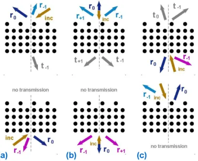
0 -1 0 -1 +1 0-1 0 -1 (a) (b) (c) (d)
-
-
-
--
-
-
-+
+
+
+
+
X X X X X Γ ΓΓ Γ ΧΧΧΧ Μ Μ Μ Μ Γ ΓΓ Γ ΧΧΧΧ Μ Μ Μ Μ Γ ΓΓ Γ ΧΧΧΧ Μ ΜΜ Μ ΜΜΜΜ Χ Χ Χ Χ Γ ΓΓ ΓFig. 1. Coupling scenarios, at which the unidirectional transmission can be obtained: green solid line – IFC of PC; blue dashed circle – IFC in air; dotted lines – construction lines; “0”, “-1” and “+“-1” denote n; “+” and “−“ at the plot top indicate that the corresponding order that propagates in air is coupled or not coupled to a FB wave, if the corrugated side is illuminated; “−“ and “X” at the plot bottom indicate that the corresponding order may propagate in air but is not coupled or evanescent, if the noncorrugated side is illuminated; IFCs of PC are loated around (a) Γ point, (b) X point, (c) M point, and (d) Γ and M points.
Fig. 2. Diffraction scenarios corresponding to unidirectional transmission in nonsymmetric PC gratings: (a) deflection and (b) splitting in the direct (forward) transmission regime, and (c) splitting in the inverse (backward) transmission regime.
If more than two orders may propagate in air, splitting with non-equal transmittances can appear in this regime. At θ =0, deflection occurs in the unidirectional splitting regime, where any pair of the symmetrically deflected higher-order beams shows the equal transmittances, see Fig. 1(c). In order to obtain T ← 0
= , the noncorrugated interface should not allow the unwanted higher orders to propagate in air. Since all the constituents are isotropic and linear, transmission has to be reciprocal according to the Lorentz Lemma [31]. To observe the reciprocity, the PC grating could be illuminated from the noncorrugated side at θ φn
← →
= , where φn
→
is the diffraction angle of the nth-order transmitted beam at the corrugated-side illumination, which is given by
1
sin [sin 2 / ].
n n kL
φ→ − θ→ π
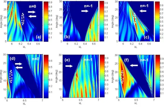
Fig. 3. Transmittance t0 t0 t0 → ← = = (a), t1 → − (b), and t1 ← − (c) at P=12, εr =11.4, and / 0.4 d a= ; t0 t0 t0 → ← = = (d), t1 → − (e), and t 1 ← − (f) at P=12, εr =9.61, d a/ =0.45, and
benchmark corrugations, direct regime.
If T t 1 T
→ →
−
= = ɶ and R→ = − ɶ at 1 T θ θ→
= , single-beam unidirectional deflection should also appear in the inverse regime, i.e., T t 1 T
← ← − = = ɶ and R← 1 T = − ɶ at θ θ φn ← → = = . The beam diagrams are presented in Fig. 2 for the coupling scenarios that correspond to Fig. 1. The following cases are schematically illustrated: single-beam unidirectional deflection (a) and two-beam unidirectional splitting (b) in the direct regime (transmission is nonzero only if the corrugated interface is illuminated), and (c) unidirectional deflection in the inverse regime (transmission is nonzero only if the noncorrugated interface is illuminated). One can see that the scenario presented in Fig. 2(a) needs asymmetry in coupling like that in Figs. 1(a), 1(b), and 1(d). In turn, the scenario in Fig. 2(b) corresponds to Fig. 1(c). Finally, the scenario in Fig. 2(c) cannot be predicted by using IFCs. It is expected to appear as a consequence of the reciprocity, as has been discussed above.
3. Results and discussion
Comparison of the unidirectional transmission efficiency for different IFC shapes (not presented) shows that for the purposes of realizing a single-beam unidirectional total transmission, the (near-)square-shaped IFCs, as in Figs. 1(c) and 1(d), are most appropriate. Figure 3 shows t0, t−1, and t+1 for the two twelve-layer structures (P =12), in the ranges of kL and θ variation, where single-beam unidirectional deflection is observed in the direct regime, i.e., when strong higher-order transmission occurs if the corrugated side is illuminated, while transmission is vanishing if the noncorrugated side is illuminated.
ε
r andd/a denote the relative permittivity of the rods and the ratio of rod diameter to PC lattice constant, respectively. Corrugations are obtained by removing every second rod from one of the interface layers of the noncorrugated P-layer PC, which we refer to as the benchmark
corrugations (L =2a). Such non-deep corrugations are expected to be more preferable than those used in [14], since the transmission features associated with the Fabry-Perot resonances should be better pronounced. Right and left arrows in Fig. 3 and in all the next figures indicate that the corrugated side and the noncorrugated side are illuminated, respectively. At the same time, smaller L/a than in [14] should make the suggested structures less sensitive to the incident beam width.
A broadband diode-like transmission is observed in Fig. 3 within the area that is approximately bounded by a white dashed line. Here, T t 1 1
→ →
−
= ≤ but T← =0, since
0 0 0
t←=t→= . Adjusting lattice parameters, one can vary width and location of the mountain of t−→1, for which the incident plane-wave energy can be entirely converted to that of the first-negative-order transmitted beam, i.e., T t 1 1
→ →
−
= = . This possibility is very important for practical applications. The obtained simulation results show that this regime is realizable while PC lattice parameters are taken from a rather wide range, e.g., 5<εr <12. The range of variation of d/a from 0.25 to 0.55 is recommended to consider first in order to find a unidirectional transmission regime. Usually, P ≥5 is required. However, using an arbitrary combination of εr, d/a, and P does not ensure the existence of the regime with T→ 1
= and 0
T ←
= .
In Fig. 3, the unidirectional transmission can be predicted by the analysis of the IFCs and construction lines, which are similar to those in Fig. 1(d). The single transmitted beam (n= −1) is negatively deflected, i.e., sgnφ−1 ≠sgnφ0. The corresponding transmission
channel is open due to the coupling of the FB wave, for which the IFCs are the near-square shaped and located around Γ point. In our case, they indicate the left handedness (S k⋅ PC<0 where S is Poynting vector and kPC
is wave vector of a FB wave), while positive refraction is
mimicked at the corrugated (here - incidence) interface. In order to estimate the range of φ−1
data in Fig. 3(b), we obtain o 1 26 φ→ − ≈ − at kL=6.2 and o 35 θ = , and o 1 10.3 φ→ − ≈ − at 6.3 kL= and o 55
θ= . For Fig. 3(e), Eq. (2) yields o 1 21 φ→ − ≈ − at kL=6.09 and o 42 θ= , and o 1 12 φ→ − ≈ − at kL =6.12 and o 55
θ= . The alternating mountains and valleys observed in the transmittance maps appear owing to the Fabry-Perot type resonances. Here, the regime of
1
T →
= might be connected with hybridization of one of the resonances and peculiar diffractions.
The Lorentz reciprocity [31] forces the unidirectional transmission to appear at a fixed θ in the inverse regime, e.g., when T ← t←1 1
−
= = and T→ 0
= . Figure 4 presents the transmittance maps obtained at the same parameters as in Fig. 3, except for the used range of θ variation. As expected, the unidirectional transmission in plots (a), (c), (d), and (f) occurs inside the area bounded by white line. The Lorentz reciprocity relevant similarity of the maps of t 1
→
− in Fig. 3(b) and t 1 ←
− in Fig. 4(c) is clearly seen. It is observed also for t 1 → − in Fig. 3(e) and t 1 ← − in Fig. 4(f). In particular, T t 1 1 ← ← − = = is achieved in Fig. 4(c) at θ φ1 ← → − = , where 1 φ→
− is the angle of diffraction of the first negative order at the mountain of T t 1
→ →
−
= in Fig. 3(b), for the kL value at which t 1 1
→
− = . The same remains true for the regimes with t 1 1 → − = in
Fig. 3(e) and t 1 1 ←
− = in Fig. 4(f). It is noteworthy that zero order is coupled now to the FB
wave at the incidence interface in the inverse regime. Then, the corresponding transmission regime can be interpreted in terms of a two-way Fabry-Perot resonance relevant transmission in a single curvilinear (bended) transmission channel. If one has a higher-order transmittance map that corresponds to the direct single-beam transmission regime, the map can immediately be plotted for the same order in the inverse regime by solving Eq. (2) for the values of θ←
. At the same time, the studied PC gratings are nonreciprocal in a wider sense, since forward and backward transmittances are not equal.
According to the obtained results, the effect of the corrugated exit interface manifests itself in the superefficient, i.e., entire transformation of the energy of the wave(s), which propagate in the PC due to the ideal coupling of zero order to a FB wave at the noncorrugated input interface, into the first-order transmitted beam. In contrast with the direct regime of unidirectional transmission where t0 =0 in a rather wide kL range around the kL-value at
which t 1 1 →
− = , now t0 ≠0 around the kL-value at which t 1 1 ←
− = . As a result, the
unidirectional transmission “point” appears in the inverse regime instead of a unidirectional transmission band, as it occurs in the direct regime. Thus, the latter should be preferable to fulfill requirements to the practical devices. The inverse regime may occur but has not yet been studied in various structures with the broken spatial inversion symmetry, which are suggested to operate at the frequencies from acoustic to optical ones, e.g., see [15–19]. One should note in Figs. 3 and 4 that t 1
←
− can be substantially larger than t0 and t 1 →
− beyond the
unidirectional transmission range.
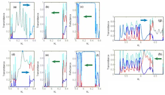
To better illustrate the basic transmission features of the single-beam unidirectional
deflection regime, Fig. 5 presents the transmittance as a function of kL for the corrugated-side [plots (a), (d), (g)] and noncorrugated-side [plots (b), (e), (h)] illumination, and reflectance for the noncorrugated-side illumination [plots (c),(f)], at fixed θ. Here, the lattice and corrugation parameters are the same as in Figs. 3 and 4. In Figs. 5(a) and 5(b), the unidirectional transmission is observed in the vicinity of kL=6.25, i.e., when ka≈π . At kL=6.25,
1 1
T →=t−→= and T← =0 in the direct regime, while the angle between the incident and outgoing beams is π θ φ1 118o
→ → →
−
Ω = − + ≈ . In Figs. 5(d) and 5(e), it occurs in the vicinity of kL=6.1, i.e., when ka<π. At kL=6.11, T t 1 1
→ →
−
= = and T← =0 in the direct regime, while Ω→ ≈116o. Figures 5(g) and 5(h) demonstrate unidirectional deflection in the
inverse regime at θ θ→ θ← = = , where o 17.3 θ← = − is the same as φ1 → − at kL=6.11 in Fig.
5(d). The Lorentz reciprocity [31] results in that T t 1 1
← ←
−
= = and T→ 0
= at kL =6.11, but
0
t remains quite large in the vicinity of this unidirectional “point”.
Fig. 5. Transmittances tn → and T→ (a,d,g), tn ← and T←
(b,e,h), and reflectances rn
←
and
R← (c,f) at P=12 and benchmark corrugations; (a)-(c): εr =11.4, d a/ =0.4, and
o 43 = θ ; (d)-(f): εr =9.61, d a/ =0.45, and o 47 = θ ; (g,h): εr =9.61, d a/ =0.45, and o 17.3 = −
θ ; blue solid line – n=0, red dashed line – n= − , cyan dotted line – 1 T→
(a,d,g), T← (b,e,h), and R← (c,f); asterisk denotes the cases of T→= (a,d) and 1 T←=1 (h).
Fig. 6. Diffraction scenario with the two beams that are simultaneously incident from the corrugated and noncorrugated sides in the opposite directions; fw and bw stand for the forward and backward cases, respectively.
In addition to the unidirectional transmission, the isolation takes place here, which is understood in the sense of the lack of interference between the two diffraction processes that is observed at the simultaneous illumination of the PC grating from the two sides being opposite to each other. The existence of this regime is clearly seen from the comparison of Figs. 5(a) and 5(c), and Figs. 5(d) and 5(f). In the former case, this occurs at
6.09<kL<6.49, where T t 1 → → − = , R r0 1 ← = = , and R r0 r1 → → −
transmitted and reflected beams propagate in different directions. In Figs. 5(d) and 5(f), this occurs at 5.94<kL<6.29. Inside this range, i.e., at kL =6.11, there are only two outgoing beams – one transmitted and one reflected, while the angle between them is 30°. Similarly, there are only two beams at kL=6.25 in Figs. 5(a) and 5(c). To demonstrate the main idea of the isolation regime, Fig. 6 presents a diagram that schematically shows the corresponding diffraction scenario.
High transmittance can be obtained in the direct and inverse regimes also for the
two-beam unidirectional splitting which occurs at θ =0. Three examples are presented in Fig. 7. In Fig. 7(a), T t 1 t 1 → → → − + = + at 8.44<kL<9.38, while 3 5 10 T← − < × Here, maxT→ 0.95 = at 9.15 kL= where o 1 43 φ→
± ≈ ± . In this case, the IFCs and construction lines are similar to those
in Fig. 1(c), and diffraction scenario is the same as in Fig. 2(b). Although T→= is not 1 achieved, the unidirectional transmission with T →≥0.9 is now more broadband and, thus, the PC grating should be weaker sensitive to the possible nanofabrication inaccuracies than those in Figs. 3 and 4. Unidirectional transmission with T→= and 1 T← ≈0 can be obtained in the direct regime at the edge of the range of T→ ≠0, as shown in Fig. 7(b). Here,
1 1 0 T → t→ t→ − + = + ≠ at 11.3<kL<12.4, while 4 4.5 10 T ← −
< × However, there is no wide unidirectional range with high transmission, e.g., with T→ 0.75
> . Thus, a compromise between the maximum value of T→ and unidirectional range width is required, being dependent on the peculiarities of a certain application. In the inverse regime, one can obtain
1 1 1
T ←=t−←+t+←= and T→ ≈0 at a certain kL value (unidirectional “point”), while zero-order transmission is well suppressed around this kL value, see Fig. 7(c). For this performance, the total-transmission peak is even wider than in the direct regime in Fig. 7(b), making it a promising candidate for practical applications.
8 9 10 0 0.2 0.4 0.6 0.8 1 kL T ra n s m it ta n c e 11 11.5 12 12.5 0 0.2 0.4 0.6 0.8 1 kL 9.8 10 10.2 0 0.2 0.4 0.6 0.8 1 kL (a)
*
(b)*
(c)*
Fig. 7. Transmittances tn→ and T→[plots (a),(b)], and tn←
and T←
[plot (c)] for the PC grating with corrugations obtained by removing every second rod from all of the eight layers (a) and one layer (b) that are adjacent to the corrugated (here - illuminated) interface, and (c) from all of the four layers that are adjacent to the corrugated (here - exit) interface, L=2a;
5.8 r=
ε , P=12, θ=0, (a,c) d a/ =0.4, (b) d a/ =0.31; blue solid line – n=0, red dashed line – n= − , cyan dotted line – T1 → [plots (a),(b)] and T← [plot (c)]; asterisk denotes (a) maxT→>0.9, (b) T→= , and (c) 1 T←= . 1
4. Conclusions
To summarize, strongly asymmetric transmission with a high forward-to-backward transmission contrast can be obtained by using conventional linear isotropic materials, provided that at least one additional transmission channel is open that differs from that is directly associated with the incident wave. In this paper, we demonstrated that the unidirectional diffraction relevant total optical transmission can be obtained in the PC
gratings with the broken spatial inversion symmetry that are made of linear isotropic materials. The basic mechanism of the strongly asymmetric transmission, which is studied here, is connected with the umklapp scattering at the corrugated input interface that can result in the appearance of one-way transmission channel(s). In contrast with the earlier studies, it was shown that the total transmission can be achieved at the corrugated-side illumination in both diode-like regimes, which we focused on, i.e., single-beam unidirectional deflection and two-beam unidirectional splitting. For the both regimes, total transmission is obtainable also at the noncorrugated-side illumination, provided that the single (in fact, two-way) transmission channel in the PC is connected with zero order, but zero-order transmission is suppressed in the exit half space. For the second regime mentioned, a higher transmittance with a relatively wide maximum occurs at the noncorrugated-side illumination, while a broader band was obtained at the corrugated-side illumination. Studies are in progress, which are aimed to infer the dominant physics of the unidirectional total transmission in order to develop a design oriented semi-analytical model. Finding PC grating performances with a broadband unidirectional total transmission will be a subject of future studies. The suggested operation regimes are promising for the design of new diode-type devices in a wide frequency range that includes not only optical but also microwave and acoustic frequencies.
Acknowledgments
This work has been supported by the projects DPT-HAMIT, ESF-EPIGRAT, EU-N4E, NATO-SET-181, and by DFG under Project Nos., SE1409/2-1 and SE1409/2-2, and by TUBITAK under Project Nos., 107A004, 107A012, 109E301. E.O. also acknowledges partial support from the Turkish Academy of Sciences.
![Fig. 7. Transmittances t n → and T → [plots (a),(b)], and t n ← and T ← [plot (c)] for the PC grating with corrugations obtained by removing every second rod from all of the eight layers (a) and one layer (b) that are adjacent to the](https://thumb-eu.123doks.com/thumbv2/9libnet/5891535.121803/10.918.181.727.572.724/transmittances-grating-corrugations-obtained-removing-second-layers-adjacent.webp)
