•2 Щ - ·» ϋ-ΐ: .,*■;: :."«.!íi-i?.í t-·;·« ■;+ ¿-к E- :.ί· : • *«·' · ·» ■·»· «» « «t 'Wl< Q A 7 6 £ ¿ l
I99S
FOR
A IR P O R T TR A F F IC
CON TROL
A THESIS
SU B M ITTE D TO THE DEPARTM ENT OF INDUSTRIAL ENGINEERING
A N D TH E IN ST IT U T E OF ENGINEERING AND SCIENCE OF BILKENT U N IVER SITY
IN PARTIAL FULFILLMENT OF THE REQUIREM ENTS FOR THE DEGREE OF
M A STE R OF SCIENCE
by
İnanç Yıldırım January 1995
•У 5 5
1995
I certify that I have read this thesis and that in my opinion it is fully adequate, in scope and in quality, as a thesis for the degree of Master of Science.
Prof. M. Akif EylerEyler (Advisor)
I certify that I have read this thesis and that in my opinion it is fully adequate, in scope and in quality, as a thesis for the degree of Master of Science.
1 n
Assoc. Prof. Varol Akman
I certify that I have read this thesis and that in my opinion it is fully adequate, in scope and in quality, as a thesis for the degree of Master of Science.
S L '■•'i ·^·
Asst. Prof. İhsan Sabuncuoglu
Approved for the Institute of Engineering and Science:
Prof. Mehmet Baray / Director of the Instituii
A N O B J E C T -O R IE N T E D S IM U L A T IO N M O D E L F O R A IR P O R T T R A F F IC C O N T R O L inanç Yıldırım M .S . in Industrial Engineering Advisor: Prof. M . A k if Eyler
January 1995
In recent years airport congestion and delay problems have received a great deal of attention due to the rapid growth of air transportation services. Of all the elements contributing to the air terminal congestion, the Air Traffic Control problem is the best understood. In this thesis we present an object-oriented model for simulating air traffic flow at an airport. The application of object- oriented design to the simulation model construction process is identified as a need, particularly for modeling large and complex systems. Object-oriented paradigm has already demonstrated that it can help to manage the growing complexity and increasing costs of the software development. The model we present here, has been implemented on a personal computer by illustrating a major metropolitan airport.
Keywords: Object-Oriented Simulation, Air Traffic Control, Object-Oriented Design, Discrete Event Simulation, Airport Systems.
H A V A A L A N I T R A F İK K O N T R O L Ü İÇİN
N E S N E Y E Y Ö N E L İK B E N Z E Ş İM M O D E L İ
İnanç Yıldırım
Endüstri Mühendisliği, Yüksek Lisans Danışm an: Prof. Dr. M . A k if Eyler
Ocak 1995
Hava taşımacılığı hizmetlerinin son yıllardaki artışı dolayısıyla, havaalanı tıkanıklığı ve gecikme sorunları daha da önemli hale gelmiştir. Hava termi nali tıkanıklığına neden olan öğeler arasında Hava Trafiği Kontrolü sorunu en anlaşılabilir olanıdır. Bu tezde, bir havaalanında hava trafiği akışı benzeşimi için nesneye-yönelik bir model sunuyoruz. Nesneye-yönelik tasarımın, benzeşim modeli kurma işlemine uygulanması, özellikle büyük ve karmaşık sistemlerin modellenmesi için, bir gereksinim olarak belirlenmiştir. Buna ek olarak, nesneye- yönelik paradigma yazılım geliştirmenin büyüyen karmaşıklığı ve artan giderini düzenleyebilir olduğunu göstermiştir. Burada sunduğumuz model, kişisel bil gisayar üzerinde büyük bir metropol havaalanı benzetimi ile oluşmuştur.
A n a h ta r S ö z cü k le r : Nesneye-Yönelik Benzetim, Hava Trafik Kontrolü, Nesneye-Yönelik Tasarım, Kesikli-Olay Benzetimi, Havaalanı Sistemleri.
I would like to thank my advisor Prof. M. Akif Eyler who has provided moti vating support during my M.S. study.
I would also like to thank Asst. Prof. Ihsan Sabuncuoğlu and Assoc. Prof. Varol Akman for their valuable comments on this thesis.
Finally, I would like to address everybody who has in some way supported me, particularly Yusuf Sinan Hûsrevoğlu, B.S., Okan Yılmaz, M .Sc., and especially Mr. Kayihan Kabadayioglu, M.Sc., Director General of Civil Aviation, for his encouraging technical and intellectual support.
1 Introduction
1.1 Air Traffic System
1.2 Air Congestion Problem
1.3 Introduction to S im ulation... 4 1.4 Outline of the T h e s is ... 5 2 Object-Oriented Programming 6 2.1 The Object-Oriented P a r a d ig m ... 6 2.1.1 Object and C l a s s ... 8 2.1.2 In h e r ita n c e ... 9 2.1.3 Polymorphism 10 2.1.4 Encapsulation... 11 2.1.5 Data A b s tr a c tio n ... 12 2.2 Object-Oriented Software ... 12 2.3 Simulation Software... 14 VI
2.3.1 Choice of Simulation S oftw a re... 14
2.3.2 Object-Oriented S im u la tio n ... 18
2.3.3 Object-Oriented Simulation S o ftw a re ... 20
3 Air Traffic Control System 23 3.1 A irp ort... 23
3.2 Air Traffic M a n a g e m e n t... 26
3.2.1 Sectors 28 3.2.2 Air Traffic Control Services 28 3.3 Simulation Modeling of АТС S y s t e m ... 31
3.3.1 Istanbul Atatürk Airport АТС S y s t e m ... 32
3.3.2 Initial Approach 37 3.3.3 Final Approach 39 3.3.4 T u r n -A r o u n d ... 41
3.3.5 The Modeling A p p r o a c h ... 43
3.3.6 Modeling V i e w ... 50
3.3.7 The Model Input D a t a ... 53
4 Implementation of the Model 58 4.1 General Object Type Design I s s u e s ... 58
4.2 Design of the Airport System Components 60
4.3.1 Initialization... 67
4.3.2 Model Run ... 68
4.3.3 Report G e n e ra tio n ... 73
4.4 Verification and Validation of the P r o g r a m ... 77
4.4.1 V e r ific a tio n ... 78
4.4.2 V a lid a tio n ... 79
5 Simulation Results and Interpretation 81 5.1 Results of the Simulation Program ... 81
5.1.1 Performance Measure Outputs of the P ro g ra m ... 90
5.2 Interpretation of the Simulation Results 91 5.2.1 The Initial Approach Arrival S e c to r ... 92
5.2.2 The Final Approach Arrival S e c t o r ... 93
5.2.3 The Final Approach Departure Sector 93 5.2.4 The Initial Approach Departure S e c t o r ... 94
6 Conclusion 96
A Apsim.pas Program 101
B Object-Oriented Turbo Pascal 106
3.1 The classification of delays around an airport, showing the
cause-effect relationships... 25
3.2 Flight path for an IFR-flight-aircraft in a controlled airspace. . . 29
3.3 Air traffic control centers and their relations with each other. . . 29
3.4 A simulated example terminal airspace in sector controller’s radar screen... 33
3.5 Istanbul Atatürk airport layout plan (not to scale)...34
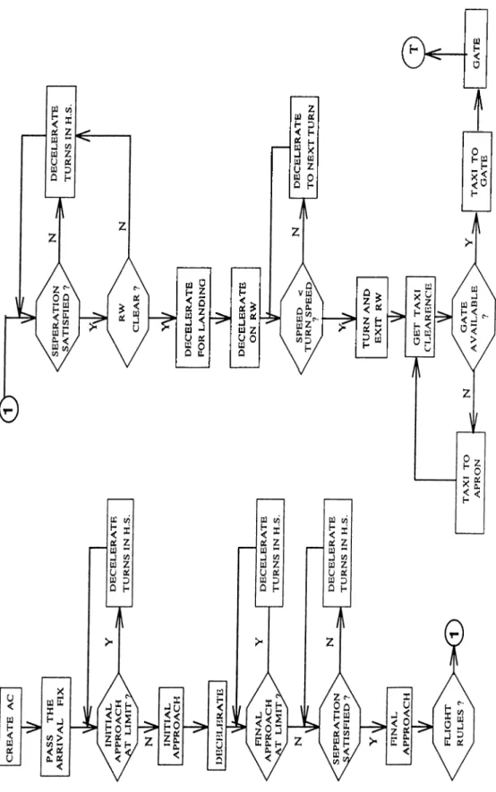
3.6 Arrival segment flow diagram... 44
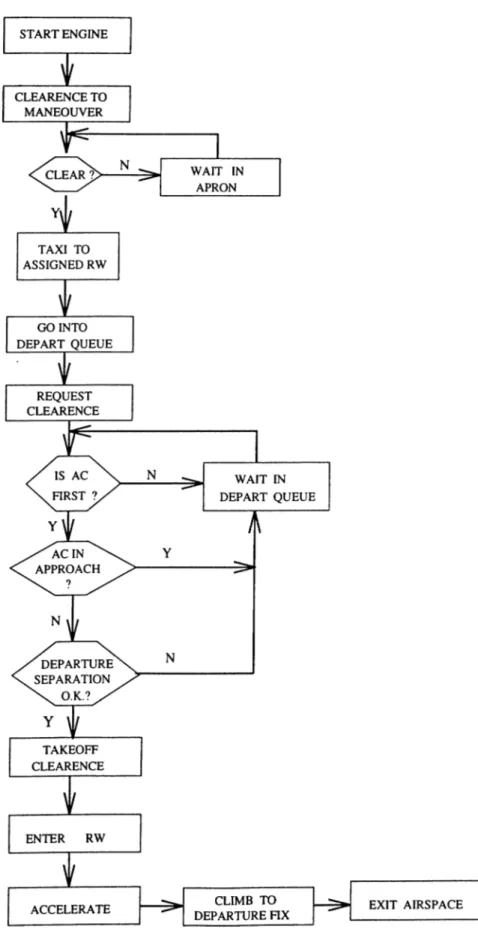
3.7 Departure segment flow diagram... 45
3.8 Turn-around segment flow diagram... 46
3.9 A sample page from the raw data f i l e ... 56
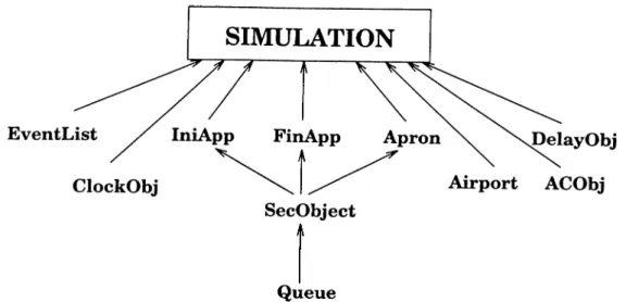
4.1 The hierarchy of the object types that are used in the airport simulation program... 62
4.2 The type declaration of object type Ev e n tLis t... 62
4.3 The type declaration for the object type CLOCK OBJECT... 63
4.4 The type declaration for the De l a yOb j e c t... 63
4.5 The type declaration for the ACOBJECT object... 63
4.6 The type declaration for the AIRPORT object... 63
4.7 The type declaration for the QUEUE object... 64
4.8 The type declaration for the QUEUE object... 64
4.9 The type declaration for the In iApp object... 65
4.10 The type declaration for the FinApp object... 65
4.11 The type declaration for the Apro n object... 65
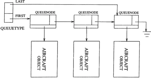
4.12 The structure of QUEUE object that uses dynamical allocation. . 66
4.13 The main program source code of the simulation model... 66
4.14 A sample page from processed input data file of the simulation p r o g r a m ... 67
4.15 A bound event flow d ia g r a m ... 70
4.16 A conditional event flow d ia g r a m ... 71
4.17 A sample output page of the simulation program ... 75
4.18 A sample output page of the simulation program (continued) . . 76
4.19 A sample page of the simulation program when the TRACE op tion is on ... 77
5.1 Average waiting times in the Initial Approach Arrival sector. . . 82
5.2 Maximum waiting times in the Initial Arrival Approach sector. . 83
5.3 Average number of aircrafts in the arrival segment of the Initial Approach sector... 83
5.4 Maximum waiting times in the Final Arrival Approach sector. . 84
5.5 Average number of aircrafts in the Arrival segment of the Final approach sector... 84
5.6 Average waiting times in the Final Arrival Approach sector. . . 85
5.7 Average waiting time in the departure segment of the Final Ap proach sector... 85
5.8 Maximum waiting time in the departure segment of the Final Approach sector... 86
5.9 Average number of aircrafts in the departure segment of the Final approach sector... 86
5.10 Average waiting times in the departure segment of the Initial Approach sector... 87
5.11 Maximum waiting times in the departure segment of the Initial Approach sector... 87
5.12 Average number of aircrafts in the departure segment of the Initial Approach sector... 88
1.1 The air-carrier crash statistics for the years between 1959-1989 . 2
3.1 Passenger traffic and increase rate in the Istanbul Airport for the last 3 years... 34
3.2 Aircraft traffic and increase rate for aircraft traffic in the Istanbul Airport for the last 3 years... 35
4.1 The objects of the program... 61
4.2 Descriptions of the data fields of the sectors in the output file of the simulation progra m ... 74
5.1 The input parameter values for the sample plottings... 82
Introduction
1.1 Air Traffic System
The demand for air transportation is growing rapidly. The growth is increasing faster than the improvements and modifications that are being made to keep the air traffic control (АТС) system properly responsive. Of all the elements contributing to the air terminal airspace congestion, the АТС problem is the best understood [22].
Each year, around 20 air-carrier crashes are detected in the world. Top causes of general aviation accidents are recorded as below [Ij:
• loss of directional control during takeoff,
• loss of control in gusty-crosswind conditions,
• failure to maintain speed,
• attempted takeoff over-weight,
• malfunctioning components,
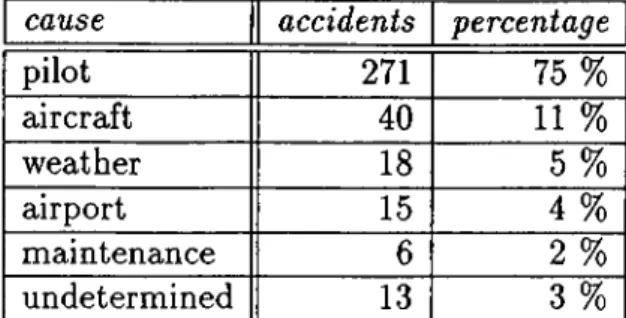
cause accidents percentage pilot 271 75 % aircraft 40 11 % weather 18 5 % airport 15 4 % maintenance 6 2 % undetermined 13 3 %
Table 1.1. 1959-1989 air-carrier crash statistics, classified by the causes of accidents.
For the years between 1959-1989, a total of 363 jet air-carrier crashes were recorded, by the International Civil Aviation Organization (ICAO). Their cat egories are given in the table 1.1.
The implications deduced from these statistics show that:
• 28 % of all accidents occured in the first 5 minutes of flight, i.e. take-off and climbing.
• 41 % of all accidents occured in the last 10 minutes of flight, i.e. final approach and landing.
These results show the great danger in aerodrome control areas, and hence the importance of the Air Traffic Control (АТС) Systems, functioning in those areas.
Beside this danger, there is another important issue created by the heavy air traffic on the airports: The proportion of flights delayed by more than 15 minutes almost doubled between 1986 and 1989. The cost of these delays to airlines and the traveling community has been estimated by the researchers at $1.5 billion annually. The total loss due to delays, inefficient routings arising from poor route structure and military airspace restrictions, non-optimal flight profiles, low air traffic control system productivity, and other inefficiencies has been estimated at $5 billion.
Lufthansa, for example, reported 5,200 hours in holding patterns over Frankfurt, Miinich, and Düsseldorf in 1987 with an increase 90 % from the preceding year. The resulting delays cost the airline more than $30 million for just these three airports alone.
Forecasts indicate that the number of passengers enplaned and deplaned will nearly double by the year 2000 and triple by 2010.
It is reported by the researchers that, sufficient capacity exists to accom o date likely growth to the year 2010, if it is efficiently organized. A commitment to timely implementation of existing airport development plans and adoption of procedural changes available in the next decade will postpone worsening air port congestion until 2010. In many cases, the cost of improvements is small with respect to continuing losses from inadequate capacity [2].
1.2
Air Congestion Problem
While present efforts to increase controller staffing, flow management, advanced radar installation and system harmonizations are essential to address the im mediate problems of the air traffic control systems, the fundamental solution to the capacity deficiencies identified will be airspace rerouting and resector- ization. For an airport system, most of the problems are caused by congested traffic. Congestion results in air crashes and huge delays; even those delays cause accidents. Therefore, the first aim of airport traffic controllers is to reduce the delays maintaining fast and safe flights.
An immediate solution to this aim can be achieved by reducing the con trollers’ workloads (e.g., resectorization of terminal airspace), and by reducing the spacing between flights which is enforced by the controllers. No simple description of the behaviour of the АТС system is available from which deduc tions could be drawn covering the effect of changes in the system parameters on the system performance.
develop a simulation model to study the complex terminal АТС system, to discover congested air traffic delays in a terminal airspace, by illustrating with a typical airport scenario. Later, we decided to extend the model to be gen eral enough to cover various airport system configurations. Several simulation studies were found in the literature; however, these studies, in general, have examined only specific subsystems of the АТС system.
1.3
Introduction to Simulation
Simulation is the process of designing a model of a real system and conducting the behaviour of the system and/or evaluating various strategies for the oper ation of the system. It is a powerful tool for the planning, design and control of systems [14].
Although simulation is very robust tool to analize systems, simulation pro grammers must be very careful about the effectiveness of their effort. Modeling is often difficult and time-consuming, and hence the modeling effort is usually much for a specific model.
Object-oriented paradigm in simulation responds to many of the questions above. It makes model building easier; objects are the natural way to describe many of the entities in a simulation study. It promotes reusability, by its in heritance principle, hence the created models can be extended to apply various similar systems (extendibility). By these two features, this paradigm increases the speed of software production. Encapsulating the code and data into an object type declaration in object-oriented design, allows modularity with the advantages of readability and maintainability. After having designed object types of the simulated system, the model can be constructed by combining these objects properly. Obviously, the objects can be combined in alternating ways to simulate similar, but different models.
The purpose of our thesis is to develop an extendible and generalizable “air traffic control system” model, by using an object-oriented approach.
1.4
Outline of the Thesis
The outline of the thesis is as follows:
• Chapter 2 introduces the object-oriented programming and describes its terminology. The issue of choice of simulation software and object- oriented simulation software are analyzed in this chapter. It shows the necessity and appropriateness of the object-oriented approach to simula tion.
• Chapter 3 describes the Air Traffic Control System that we model. It introduces the basic air traffic procedures enforced in the airports, and analyzes the Istanbul Atatürk Airport System as a particular case. The chapter gives the design and the modeling approach for that airport.
• Chapter 4 deals with the design and implementation of the airport com ponents that we used in our study. It gives the declarations of the object data types and their hierarchy. It describes the execution and outputs o f the program. Then the verification and the validation issues of the simulation program are considered.
• Chapter 5 gives the results and the interpretation of these results. The simulation program was run with different parameters and input data files, to analyze the sensitivity of the model to these parameters, and to illustrate the applicability of the model to different air traffic control configurations. In this chapter, the results are shown numerically and graphically, then interpretations of these results are given.
• Chapter 6 concludes the research. It discusses the research and combines the ideas of the study. Finally, ideas and suggestions related to future work to extend the research study are stated in this chapter.
• Appendices provide with the object type declarations that are used in our program and a brief discussion of object-oriented Turbo Pascal lan guage. A small glossary for the aviation terminology is also supplied as an appendix.
Object-Oriented Programming
This chapter gives a brief introduction to object-oriented paradigm. The funda mental object-oriented concepts, which include data abstraction, encapsulation, inheritance, and polymorphism, will be explained in this chapter. The chap ter also provides an overview of object-oriented languages and their evolution. Then object-oriented simulation will be introduced.
Object-oriented design and programming represent a major paradigm shift in software engineering during the 1980s. End-users, systems programmers, and application developers, in particular, simulation programmers, are all ben efiting from object-oriented modeling and programming techniques.
2.1
The Object-Oriented Paradigm
A programming paradigm provides the system designer with techniques that guide problem solution. With the increasing demand in computer applica tions in all areas of science and business, software products have to satisfy more sophisticated requirements. Programmers must use more complex data structures and intelligent algorithms.
Program developers have long been educated mainly in the procedural paradigm. This is traditional, function-oriented approach to programming and
in this paradigm, subprograms (e.g.,functions, subroutines or procedures) are the most important part of the programs.
All code in a program is designed around the subroutines. Data are exe cuted by the subroutines, they are passive in this process. It means that data are only passed to or from these subprograms.
For many years, programming languages and tools have been designed to take advantage of the concepts of structured design. Structured languages help software developers to write more organized code. However, in many respects these languages and tools haven’t provided enough flexibility to handle the complexities of modern software requirements. Recently, by these motivations, there has been growing interest in utilizing some of the alternative paradigms to the procedural paradigm to facilitate the solution of certain types of problems 121].
1950s 1970s 1990s
Assembler Structured Object-Oriented
gotos blocks objects
jumps subroutines messages
variables recursion classes
Object-orientation is a newly accepted and important paradigm for im proving software construction, maintainance and use. Object-oriented pro gramming has changed the programming strategies and increased the speed of software production. In fact, it is not a new concept. The main ideas behind object-orientation occured in the late 1960s, but not widely used till 1990s.
Object-oriented paradigm has already demonstrated that it can help to manage the growing complexity and increasing costs of software development.
Object-oriented programming enables a program to be written with a fo cus on the description of the problem rather than algorithms for solving the problem. According to Meyer [17]:
” ...object-oriented design may he defined as a technique which, unlike clas sical ^fiunctzonalj design, bases the modular decomposition o f a software system on the classes o f objects the system manipulates, not on the functions the sys tem performs. ”
Coding an application program in this paradigm involves creating a set of objects with the proper methods that will be invoked at the appropriate time through message passing among these objects.
Object-oriented programming has its roots in simulation. The first object- oriented programming language, SIMULA, was developed to provide simula tion facilities within a general purpose programming language.
Object-oriented programming embodies four key concepts which result in making software systems more understandable, modifiable, and reusable. These concepts are: encapsulation, data abstraction, late binding, and inheritance. The definitions of these new terms will be explained in the following subsec tions.
2.1.1
Object and Class
In the object-oriented paradigm, objects and classes are the basic elements of the programs. A class is that software module which provides a complete definition of the capabilities of members of the class. An object is an instance of a class. In other words, a class is a template that is used to define an object. Rather than describing each object, objects of similar data content and behaviour are grouped together into a super-entity, called a class.
A class contains two types of components: data and procedures; so that it keeps both the characteristics of an entity (its data) and its behaviour (its procedures). By melding these characteristics and behaviors, a class, and hence its instances, know everything they need to do their work.
the ‘class inheritance’, new classes can be derived using the existing classes. This new classes, called subclasses or childs of the existing one, which is called, superclass or parent, have now their own code plus that of their parent.
Besides providing a brilliant mechanism for organizing information, the most important contribution of class inheritance is code sharing or code reusabil ity.
2.1.2
Inheritance
Inheritance is a powerful object-oriented concept that provides software reusabil ity and software extensibility. It ‘ taxonomizes’ objects into well-defined inher itance hierarchies, by its natural organizing mechanism.
Inheritance is the ability to define new types of object which have some of the properties of old types, and some new properties of their own. New classes can be constructed from existing ones by extending, reducing, or otherwise modifying their functionality. New classes are specializations, or extensions of their superclass.
An inheritance hierarchy results from successive uses of this specialization principle. The inheritance hierarchy makes the definition of new classes more economical, since they can be derived from existing classes. Obviously, the deeper the hierarchy, the more functionality is inherited by the new class.
Inheritance provides a flexible programming environment that is organized in a hierarchical structure of object classes with reusable programs. This also leads to extensibility.
A base class may have multiple derived classes, and a derived class maj^ in turn serve as the base class for other derived classes, producing a tree- structured organization of classes. In single inheritance, no more than one class can be base class for any derived class. However, in multiple inheritance, this can happen. Multiple inheritance permits a class to have multiple parent
classes. It is useful in building composite behaviour from more than one branch of a class hierarchy. When a class inherits from more than one parent class, there is the possibility of conflict of methods or variables with the same name but different, and unrelated semantics that are inherited from different super classes. Furthermore, this feature violates the tree-structured organization of class hierarchies. Because of the reasons stated above, the multiple inheritance concept is not implemented by some of the object-oriented softwares [16].
2.1.3
Polymorphism
Polymorphism is Greek word for ‘many shapes’ . It is the method for changing the behaviour of a component that is shared by different objects.
As inheritance concept highlights, a derived class distinguishes itself from its base class by adding member variables, adding member functions, or re defining inherited member functions. In the last case, a member function declared in a base class may have several definitions since it may be redefined in multiple derived classes. When the function is called to perform an op eration on an object, the definition actually used is determined at execution time based on the class of the object. This strategy is called dynamic or late binding. Binding in programming refers to the time at which values are asso ciated with variables. In contrast to early or static binding (e.g., binding at the time of code construction) in traditional procedural languages, late binding provided in object-oriented programming languages delays the binding process until the software is actually running. Dynamic binding encourages placing the code that deals with a particular class of object in the implementation of the object’s class, rather than in the client program, thereby making the client program more general.
By the dynamic binding feature, polymorphism places the responsibility for correct action on the object; the same message sent to many objects will illicit different, but appropriate behaviors.
a message can be sent to an object requesting it to perform some action, with out having to know what type of object it is, until run-time. Often the method for handling a message is stored high up in a class hierarchy. The method is located dynamically when it is needed. Binding then occurs as the connections are made between the method and the data local to the object. That is binding occurs at the last possible moment.
2.1.4
Encapsulation
Encapsulation is an object-oriented property that a software object is a com pletely self-contained entity, possessing all the data and code needed to perform a set of standard operations which form its only interface to other objects [17].
Generally, encapsulation serves three purposes:
• It protects an o b ject’s data from getting too much exposure,
• It makes it easier to use an object's data through the object’s own inter face,
• It is used to hide the details.
Encapsulation means that an object’s data and procedures are enclosed within a tight boundary, one which can not be penetrated by other objects. Data stored within an object is directly accessible only by the procedures that have been defined as part of the class to which the object belongs. The use of objects therefore improves the reliability and maintainability of sj'^stem code.
According to concept of information hiding, each software unit encapsulates its data and procedures and permits access to its internals only through a well specified interface. In object-oriented programming, objects communicate with each other by sending messages requesting them to perform their behaviors {message passing). Objects can query other objects to find the value of an internal state variable, but they can not directly change its value.
For many applications, it is desirable to decompose the program into a set o f smaller parts which can be managed separately. There are two primary advantages of decomposing a problem into smaller parts: first, all elements and facets of the task can be seen more clearly; second, the parts can be developed and tested incrementally. The result of decomposition should be a set of modules which can be executed independently or combined to execute as an integrated whole. This programming technique is called as modularity and provides an important idea for structured programming. By the encapsulation concept in object-orientation, modularity is automatically reflected, since each class in an object-oriented program is treated as a module.
2.1.5
Data Abstraction
Data abstraction is the ability to treat the definition of a single object as an abstract entity which can then be used to define many further objects of the same type, all with independent data.
Data abstraction is implemented in a language as the ability to create new types o f which variables are declared. In object-oriented languages, this is the ability to declare an object to be of a certain class. Class corresponds to an abstract data type and object corresponds to a variable of that abstract type. Data abstraction provides the ability to focus on what is relevant in modeling the problem. It makes the programming easier because there is more reusable code available.
2.2
Object-Oriented Software
Programming based on objects was first developed in SIMULA 67 language, evolved from SIMULA I, which is a simulation extension to the ALGOL-60 programming language. In the 1970s SMALLTALK was created as the first pure object-oriented language. It has evolved from the artificial intelligence
applications. SMALLTALK was influenced by SIMULA’S model of com pu tation and added the message passing paradigm, creating the object-oriented programming style [14] [21].
They are widely used in the academic area, but not so popular in commer cial environment until the 1980s. At that time, C programming language was accepted as one o f the best program development languages, by many software engineers. Bjarne Stroustrup introduced object-oriented paradigm to C to cre ate C-b-f language. Because of its roots in C, C-|-+ language introduced the object-oriented programming concept to many programmers without having to learn new and unfamiliar programming languages [11].
Authors state the fact that the choice of language is primarily based upon the availability of the language to the user and the user’s knowledge of the lan guage. This reason rather than the appropriateness or performance capability of the language is the overriding criteria.
Object-oriented programming usually requires less coding and its programs are easier to modify. However, the use of object-oriented programming was not likely to gain widespread use for simulations unless the language used is widely available and is familiar to a large number of simulation developers. Consequently, it appears that simulation through C-I-+ or Turbo Pascal is more likely to be successful in this regard than other alternatives such as SIMULA, SMALLTALK, etc. Latter languages suffer from limited availability and a more restricted user base.
In addition, for the distributed simulation environments, object-oriented paradigm shows more promise, by assigning each object to different parallel processors.
Finally, it is important to emphasize that the use of object-oriented tech niques is not dependent on any particular programming language. Rather it is an approach to organizing and planning computer programs which can be ap plied to a greater or lesser extent in all software development. Object-oriented programming is a paradigm, not a programming language. Therefore it can
be implemented in many languages, whether these languages are said to be an object-oriented programming language, or not. For example, object-oriented toolkits in ADA and FORTRAN , which are not object-oriented programming languages, can be found in [16].
2.3 Simulation Software
Recent improvements in computer hardware and software technology has brought wide horizons to simulation. Advanced technology provides with common and effective utilization of simulation models in the industry. This also resulted in the issue of selection o f an appropriate simulation software for a particular application, among the wide variety of products.
2.3.1
Choice of Simulation Software
One of the most important decisions a simulation analyst has to make in the development of a simulation study is the choice of a particular language. A wrong decision may yield undesired results for the study.
For the selection of an appropriate simulation software, a simple m ethod ology must be followed:
• detection of simulation software market,
• understanding of software classification and features,
• identification of the modeler and the proposed end-users of the simulation model and determination of their experience and skills.
Following the above approach, the main decision to be made occurs for deciding whether a general-purpose or special-simulation language to use.
For most of the applications, the features that are needed in programming discrete-event simulation models are common. Some of these common features may include:
• a reliable random number generator,
• probability distribution functions,
• future event list,
• simulation clock,
• abstract data structures such as queues,
• functions for data collection and database management,
• functions to generate reports,
• functions to handle erroneous cases,
• interfaces.
To build a simulation model by using a particular simulation software, the software is expected to have some more features;
• M o d e lin g fle x ib ility : Simulation software must have enough capabili ties to handle variety of applications, to promote reusability.
• U se r -fr ie n d ly : Simulation software must be easy to use and develop applications. Interactive debuggers and on-line help facilities are the two basic elements to improve model development time and model credibility. •
• E x e c u tio n sp e e d : Since simulation models usually require multiple replications or multiple cases to be run, or both simultaneously, they use a lot o f computer time. Even when computational resources do not present a direct cost to project, calendar time itself may limit the scope of the study.
• M a in ta in a b ility : Experiences have shown that simulation projects are evolutionary in nature. Requirements change, the system being simulated changes, and the goals of the project change throughout the life of the study. Maintainability extends the life-time of the study.
• Size: Long code of an application means, difficulty for debugging and maintaining.
• P o rta b ility : If the simulation product is to be delivered to outside, or if there is a possibility of change of computer resources, usually this is the case; software is expected to be portable, that is, it can be run on various computing environments.
• C u sto m e r s u p p o r t: Good documentation and technical support assis tance satisfy the simulation model developers’ requirements.
After having discussed the desirable features of a simulation software, we can turn back to the question of selection among a general-purpose or simula tion language. Now we can see some guidelines by the light of above discussion.
A simulation language, automatically allows the programmer to create m od els with the features listed above. This decreases the programming effort and development time. Studies result with smaller program codes, and hence the chance of making errors is reduced and debugging process is improved.
On the other hand, with the general-purpose programming languages, gen erally faster programs can be coded, since these programs are written for spe cific applications, ignoring the modeling flexibility. These languages are likely to be used widespread!}', known by many people. They support dupHcabil- ity, that is more flexible to model any real-world system. General-purpose languages are available in most of the computing environments, with cheaper prices.
When we look at the history of simulation, we see that language of choice changes as the software technology evolves. Early simulation modeling was
performed using custom programs written in general-purpose computer lan guages, such as FORTRAN. Although this approach proved the viability o f simulation modeling, the models were typically expensive and time consuming to design and maintain. Usually, the work done on a specific modeling project could not be easily utilized during subsequent modeling efforts. This resulted in simulation being used primarily on large, expensive projects.
In the early 1960s, as the field of simulation developed further, discrete event simulation languages such as GPSS, GASP and SIMULA were intro duced. These languages were primarily written in general purpose languages but provided generic functions and subroutines to perform many o f the tasks routinely required in simulation. At that time, the bulk of the simulation model development effort was still spent in developing problem specific code that had little reusability in future problems. In the late 1960s a second gener ation of simulation languages emerged. In most cases (e.g., GPSS V, SIMULA 67 and GASP IIA), these languages were more powerful replacements o f their predecessors.
In the 1970s, as the use of simulation modeling grew, developments in simulation languages were driven toward the extension of simulation specific languages to facilitate easier and more efficient methods of model translation and representation. Many of the languages which evolved from these devel opments, GPSS, SLAM, and SIMAN, are still widely and actively used today [14].
In terms of continuing the growth of simulation modeling and expanding the use of simulation in general, construction of new simulation models and m od ification of existing models still provide formidable challenges to researchers. Also, the time required to construct and validate simulation models must con tinue to decrease through the use of concepts such as rapid prototyping and model reusability. Object-oriented programming appears to have the potential to be a major contributor to these areas of research.
2.3.2
Object-Oriented Simulation
Recent searches for better approaches for implementing simulation models is the recognition of the compatibility between simulations and recent develop ments in the area of expert systems; In particular, it seems that the object- oriented programming approach of expert systems is appropriate for imple menting simulation models. Object-oriented design presents a more natural way of describing the problem with a one-to-one relationship between real- world objects and modules.
In general, modeling a real-world system can be viewed as identifying the components of the system and defining the interactions of these components with each other.
The guidelines of object-oriented simulation code development can be stated as follows [13]:
1. Identify the components and processes of the system that is under study (entities).
2. Define an object class to represent each entity of the system along with its interface.
3. Characterize the conditions that lead to changes in the system state, treat these as events and specify the actions of scheduling, occurence and results o f these events in the object classes they are related.
4. Develop the main program which creates the entities of the system.
Consider the design of the discrete event simulation. Using a procedural design paradigm, the focus would be on an overall command loop which would be decomposed into subtasks as the design progressed. Data structures such as queues would be introduced as needed to support the algorithm. Using the object-oriented paradigm the main focus is on the entities in the simulation domain such as queues, servers and customers.
Each entity is defined abstractly in terms of a class. The actual entities in a problem solution are then represented as instances of these abstract classes. The instances are implemented as objects, independent regions of memory. For the discrete event simulation, classes would be defined for queues, servers, and customers. An instance of class customer would be created for each customer introduced into the simulation. In addition to identifying entities, object- oriented design also identifies relationships between these entities. These rela tionships help define the structure of the application design.
Once one accepts the principles of object-oriented program design, one must address the problem of decomposing the problem at hand into a suitable set o f objects. This is usually not too difficult, if one can view the the proposed program as a model of some aspect of the real world. Then there is a natural correspondence between the objects being modeled and their program counter parts. This is most certainly true in the case of simulation where the specific intent is to represent objects from real life with a computer program. Nothing could be more natural than to organize the program structure around the ob jects being simulated. This aspect of the object-oriented paradigm is perhaps most significant to simulation.
Issues of modularity, maintainability, reusability, extendibility and the quite natural relation between real-world objects and their simulated counterparts all argue in favor of object-oriented programming technique. Object-oriented programming languages provide these advantages through such mechanisms as inheritance, dynamic binding, polymorphism, and automatic garbage collec tion, generally at the expense of execution time overhead.
As explained in the previous sections, inheritance mechanism of object- oriented paradigm reinforces reusability. By the class libraries, (e.g., tool boxes), frequently used classes are kept in separate program units. Subclasses of the classes in these libra;ries can be created by inheritance mechanism, with out redefining their superclasses. Libraries provide modularity. If class libraries
are carefully designed, then these libraries do not contain any application- specific classes; rather, they have general classes to handle varieties of ap plications, so that flexibility is promoted. This approach also allow to build extendible models by the polymorphism principle; by which we can overwrite a member function of a class.
The key concepts of object-oriented paradigm reduce programming effort and increase project development speed. Carefully-designed simulation class libraries supports less sophisticated programmers, who are to assemble appli cations quickly from the prefabricated parts to model a system.
2.3.3
Object-Oriented Simulation Software
As stated above, object-oriented programming has its roots in simulation. SIM ULA 67 was developed by Kristen Nygaard and Ole-Johan Dahl, to provide simulation facilities within a general purpose programming language. However, it has not gained widespread use for commercial simulations. This perhaps is due at least, in part to fact that it is an ALGOL based language and in many instances requires the writing of ALGOL subroutines in order to simulate a complete system. While SIMULA embodies some of the concepts of object- oriented paradigm, it is not a pure object-oriented programming language. One recent language based on the object-oriented approach is the SMALLT.'\LK language, which added message passing paradigm to SIMULA.
SIMULA and SMALLTALK have found popular academic use, but have never gained widespread use in the commercial environment [13].
Until the 1980s, object-oriented simulation software is limited to academic research applications. At that time, C programming language was accepted as one of the best program development languages, by the authors. Bjarne Stroustrup introduced object-oriented paradigm to C to extend it to C -f + lan guage. The first implementation o f C-|--(-, was developed as a preprocessor for C compilers at AT&T laboratories. Because of its roots in C, C + + language introduced the object-oriented programming concept to many programmers
without having to learn new and unfamiliar object-oriented programming lan guages. The availability of the language to the user and the user’s knowledge o f the language, makes the C-|-+, the leading object-oriented language [11].
After the success of C -f+ , some other general-purpose languages released their object-oriented versions. Object Pascal, Turbo Pascal 5.5, Objective-C, and COBOL are most popular ones among these compilers. They are not pure object-oriented languages, but provide more efficient and strongly type-checked implementations.
C-b-1- features “in-line” function declarations, use of which can produce very efficient code. Another feature of C-b-f is useful in general and for simulation purposes in particular is the “friend” relation. A class can declare another class to be a friend, the second class then has free access to all of the inter nals of the first class. Currently, there are various simulation languages and packages based on C-b+, providing with the initial libraries to ease the model development. SIM-b-b is such a package for writing distributed simulations to run on multiprocessors, and DISC-b+ is a well-known discrete-event simulation library supporting event-scheduling and process interaction world-views.
With the version 5.5, that is released in 1988, Turbo Pascal had the object- oriented extensions. The “unit” feature, from previous versions, provides en capsulation of procedures with data and hiding. The object-oriented exten sions provide single inheritance and virtual functions, hence pol3miorphism. The Borland integrated development environment facilities program develop ment. It would be an acceptable medium in which to develop simulations. On the negative side is the fact that, at least at present, it is restricted to the PC world.
SMALLTALK-80 is a prototypical pure object-oriented language; every thing without exception, is an object and all operations are accomplished by message passing. Automatic garbage collection is provided. It has a graphi cal interface that includes editor, class browser, debugger and object inspector. On the other hand, SMALLTALK programmers spend a substantial amount of time, familiarizing themselves with the workings of the initial class hierarchies
o f the programming environment. SMALLTALK-80 has built-in support to facilitate the use of objects and classes of objects to model entities and events that occur in discrete-event simulations. The objects within such an environ ment, however, exist only for the duration of the simulation run. They must be created at the outset and saved (or destroyed) at the end. SMALLTALK pro vides the feature that automatic management storage reclamation of objects that are no longer needed. This mechanism is called automatic garbage col lection in object-orientation. Recently, object-oriented methodology has been applied to data base technology. With the advent of object-oriented data, bases it is possible to extend the life of objects beyond the run-time of a program.
Air Traffic Control System
In recent years, airport congestion and delay problems have received a great deal of attention due to the rapid growth of air transportation services. The de lay in an airport system increases rapidly when the air transportation demand approaches the maximum capacity of that system.
“ Crowded sky syndrome” limits the development of air transportation. But, the fact is that the potential of the airspace have not been used completely as a transportation medium. It is the system that is crowded, not the sky.
In this chapter, we describe the general standard air traffic control system procedures and airport operations; and then look at a particular aerodrome to identify the practical use of these procedures to construct a model for air traffic control system.
3.1
Airport
Since all traffic originates and terminates at some point on the earth’s surface, the overall efficiency of the air traffic control system is directly affected by the adequacy of the landing/takeoff areas, or “airports” .
Improvements in airports thus must be undertaken constantly as part of
Aerodrome Passenger (million) O ’ Hare 64.44 Dallas 51.9 Los Angeles 46.9 London 45 Tokyo 42
overall improvements in the air traffic control system, and in keeping with the development of new aircraft and expanding air traffic volume. Unless airport progress keeps pace with all of the technological advances in aviation, airports can become one of the most serious bottlenecks in the path o f efficient and safe air transportation.
An airport system can be divided into six components :
1. Airspace, 2. Runway, 3. Taxi way, 4. Apron-gate, 5. Terminal building, 6. Ground-access facility.
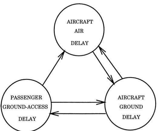
The first four items in the above list are involved in the air traffic system, while the last two items, theoretically, must not affect the air traffic. The layout of the airport terminal buildings and location of the airport have no influence on the aircraft movements, but they are likely to impose delays for the passengers ( Figure 3.1 ).
Among the components of an airport system, the airspace and the runway are usually the critical components which limit the airport capacity.
Figure 3.1. The classification of delays around an airport, showing the cause-effect relationships.
There are two major factors restricting the capacities of airspace and run way components; minimum separation criteria for two consecutive landing or departing aircraft and runway occupancy time. Limitation of the capacity re sults in delays. The delays which are imposed on airport traffic can roughly be classified into two categories; first is the delays due to the composition of the traffic, and second is that due to runway non-availability [20] [19].
The delays due to the composition of the traffic have been identified where the delay imposed was not due to runway non-availability, but due to the order of each aircraft in being sequenced by the air traffic controllers. Thus the same set of aircraft may require very different delays because of a slight change in their order. The minimum separation criteria are imposed on the landing and takeoff procedure to prevent aircraft mishap due to inadequacies in the air traffic control system, and due to the wake vortices generated by the leading aircraft. These criteria however, expected to decrease as a result of ongoing research efforts that address the reduction of wake vortex and the improvement of air traffic control system [5] [12].
The delays due to runway non-availability are affected by the number of runwa}'^s in use, and separation minimum criteria, that is used similarly, to avoid collisions and wake vortex. Unfortunately, for the sake of safety, an aircraft is not allowed to use runway if another aircraft remains on the same runway, or in the final approaching phase of landing. Hence, the capacit}' of an airport would not increase proportionally as the minimum separation criteria decrease, unless the runway occupancy time decreases too; where the runway occupancy time is defined as the time interval from the instant the landing aircraft passes over the runway threshold until it completely clears the runway [7] [6].
3.2
Air Traffic Management
An easy solution to the delay problem is to limit the volume of air traffic which can use the airport under specified conditions or periods of time; but this is
not a cure for the problem.
In order to meet public demand in a total transportation concept is to apply more effective methods to achieve the highest possible degree of efficienc}'^ in the use o f airspace and airports. This objective depends to a large extent on the capability of the overall Air Traffic Control System. The objectives o f an air traffic control service, as defined by the International Civil Aviation Organization (ICAO), are to [1]:
• Prevent collisions between aircraft in flight
• Prevent collisions between aircraft on the maneuvering area of an airport and obstructions on that area
• Expedite and maintain an orderly flow of air traffic
• Provide advice and information useful for the safe and efficient conduct of flights and notify appropriate organizations regarding aircraft in need of search and rescue aid, and assist such organizations as required.
The degree of air traffic control exercised by this system depends basically on the meteorological conditions in which an aircraft is flown. When an aircraft can be flown clear of clouds and the pilot has good visibilitj'^, the flight is conducted in accordance with “visual flight rules” and is referred to as a VFR Flight. V F R flights are subject to little or no control by the ground facilities. It is up to the pilot, to watch out for the safety of his/her flight in the “see and be seen” environment. If a flight can not be conducted in accordance with VFR, it must be conducted under “instrument flights rules” , or IFR Flight., and the ground facilities exercise positive separation control over all such flights. Traffic control procedures and parameters differ for the two types of flight conditions.
Long-range radars which provide position information, and computers which performs many of the routine functions of the controller, are utilized to assist the controller to achieve desired separation between aircraft.
3.2.1
Sectors
In order to maintain a controller’s workload at a level which is within his capability to handle, the center’s airspace is divided into sectors. This airspace is a defined geographical area which encompasses a number of airways or routes, airports, and navigation aids, and is also defined vertically [1]. Each such sector is assigned an appropriate number of controllers and assistants who are responsible for all aircraft in their designated airspace. In effect, the center’s airspace is divided into small portions of the whole airspace, each of which will normally contain a small number of aircraft. Provision is made to combine sectors during periods of low traffic densit}^ and to further subdivide certain sectors when the volume of traffic reaches the point where a single controller can no longer handle the traffic.
Each sector has a controller who is directly responsible for the control of air traffic within his/her assigned airspace. The radar and communications equipment provide, in general, the means by which controllers receive position data on aircraft and through which air traffic center instructions are conveyed to pilots. In order to determine the correct instructions, it is essentia] that the controller be fully cognizant of the position and future plan of every aircraft within his/her sector.
3.2.2
Air Traffic Control Services
Air traffic control services are provided by area control centre, approach control office and aerodrome control tower. These services are provided to all IFR and V F R flights in controlled airspace and to all aerodrome traffic at controlled aerodromes.
1. Area control service : the provision of air traffic control service for con trolled flights, except for those parts of such flight described in sub- paragraphs 2 and 3 below, in order to accomplish objectives of preventing collisions between aircraft; and expedite and maintain an orderly flow of
Figure 3.2. Flight path for an IFR-flight-aircraft in a controlled airspace.
air traflSc. This service is provided by an area control centre or approach control service unit, if no area control centerA is established. They are also called, air route traffic control center, since they provide enroute traffic separation to IFR flight aircraft in controlled air space. They are responsible for large areas of controlled airspace. This facility is divided into several sectors, each of which use its own frequency and responsible for radar coverage of a particular area.
2. Approach control service : the provision of air traffic control service for those parts of controlled flights associated with arrival or departure, in order to accomplish the same objectives as listed above. This service can be provided by an aerodrome control tower or area control centre ; or by an approach control office when it is necessary or desirable to establish a separate unit.
These facilities control an area of from 25 to 60 nautical miles from their airport. Arriving traffic is passed from the cognizant center to the approach control sector, and the reverse process takes place for departing traffic. In certain cases, the approach or departure control sectors may be subdivided into smaller sectors to reduce the controller workload.
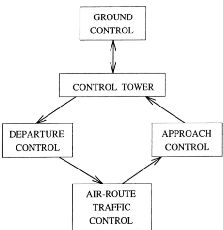
3. Aerodrome control service : the provision of air traffic control service for aerodrome traffic, except for those parts of flights described in sub- paragraph 2 above, in order to accomplish the objectives stated before, plus for preventing collisions between aircraft on the manoeuvring area, and obstructions on that area. This service is provided by an aerodrome control tower. The tower normally accepts air traffic from approach con trol service at about the point where the aircraft can be visually identified. The control of air traffic on or in the vicinity of an airport is provided by this facility.
Departing aircraft are given instructions regarding when and how they may taxi from loading ramp to the runway in use, followed by takeoff clearance when the pilot is ready and the traffic permits. Arriving air craft are handled by the control tower in a similar manner, by “clearing” the aircraft to land when airborne and ground traffic permits, and then
by issuing appropriate taxi instructions to guide the aircraft to its un loading point. There may be an additional unit to help the tower, called ground control or ramp control. This unit governs the movement of air craft and other vehicles on the airport, excluded the active runways. It takes aircraft from apron to runways or vice versa.
Figure 3.3 gives the direction of control of an aircraft using an airport. Figure 3.2 shows a typical flight path of an aircraft through the air traffic control centers.
Under the present air traffic control system, when an aircraft reaches its destination, the approach control provides the necessary directive to maneu ver aircraft and aline each with the desired runway for landing. Aircrafts are permitted to land on a first-come first-served basis, under the normal condi tions; in approach sector, a separation minima between aircrafts is enforced. A normal landing will ensue if tower controller give the clearance, and if the pilot, in approach maneuver, is able to stabilize his/her aircraft in a landing configuration by the time the minimum decision altitude of 200 feet is reached. After exiting the runway, landing aircraft is directed to its assigned gate, if it is available, or to a parking place on the apron, using the taxiways. Departing aircrafts are similarly, put into a depart queue, and cleared to roll on the run way; if the aircraft is in the first place, and if there is no other aircraft on the same runway and in the final approach sector. Departure controller maintains the flow of air traffic till the departure fix, which is the exit point of aerodrome control area, on the air-route.
3.3
Simulation Modeling of A T C System
In this thesis, our objective is to study and analyze the effects of different parameters and strategies, that are applied by the air traffic control system, on the total delay of aircrafts in that airspace. In order to achieve this ob jec tive, we select a crowded airport, which has suffered from the critical capacity problems in recent j-ears, to study on. We decided to use the Istanbul Atatürk
Airport for our modeling purpose. This was the biggest one with the most serious delay problems, among the total of 22 airports in Turkey.
We tried to build a model that can be applicable to any air traffic control system configurations. We also tried to be as realistic as possible, since the ICAO procedures mentioned earlier are subject to change by the particular countries, with their own responsibility. During our observations, we saw that, no one of the АТС systems, applies the ICAO rules strictly. The limits, that are imposed parameters by ICAO, can be implemented in a flexible way, to ease the job of air traffic controllers.
3.3.1
Istanbul Atatürk Airport А Т С System
Istanbul Atatürk airport is the biggest one of the five international airports that accept scheduled flights, in Turkey. In fact, 47 % of total air traffic and 45 % of total passenger traffic of Turkey, are handled by this airport. For the last few years, the increment rate of aircraft and passenger traffic in this airport is beyond the all forecasts, that are made by international АТС authorities. The growth brings on the capacity problems; for both of passenger terminal buildings and aircraft maneuvering spaces.
The Atatürk Airport
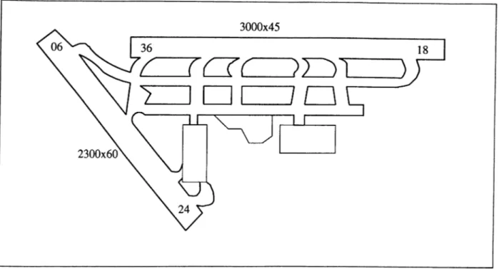
The Atatürk airport has two converging runways, (36/18 and 24/06), that is, extension of centerlines are intersecting each other. The dimensions are: 3000 X 45 meters for runway 36/18 and 2300 x 60 meters for runway 24/06.
The former runway has seven turn-off points to exit, and the latter has six. The current runway capacity is 40 movements (take-off or landing) per hour, and under adverse conditions (4 to 5 months per year), operations are limited to single runway use with the capacity of 24 aircraft movements per hour.
The only capacity enhancement for the runway, that is planned, is an ex tension of 700 meters to runway 24/06 is under study. By the implementation
a (D i-, o 00 ' - a ca o E— <2: CO CD U C3 CIO
Figure 3.5. Istanbul Atatürk airport layout plan (not to scale).
year capacity passenger % increase peak day peak hour
1991 7,500,000 5,204,500 _ 21,188 1,674
1992 7,500,000 7,371,600 42 37,936 2,751
1993 8,500,000 9,396,230 27 47,675 3,215
Table 3.1. Passenger traffic and increase rate in the Istanbul Airport for the last 3 years.
of this project, runway performance capabilities will be enhanced.
The tables 3.1 and 3.2 reflects the growing traffic capacit}'^ problems in the Istanbul airport.
There are 11 apron areas for parking, and these areas can hold 64 aircrafts. Nevertheless, inadequacy of parking places imposes a constraint on the traffic of the airport. For the emplane/deplane processes, there are 9 gates at the international terminal building, and the rest is performed by mobile ramps.