OBJECT-ORIENTED ΜΟΊΊΟΝ ABSTRACTION
î‘S2S ί'αΒΜ ΪΤΤϊΏ - T í y if С О Ы Р о І З Н S K чЗXiîE 31İ2ii ϊιΙιΟ'ϋΖτίτΙίΝίΙϊΐ:T R
837.7
• £75
7393
OBJECT-ORIENTED MOTION ABSTRACTION
A THESIS SUBMITTED TO
THE DEPARTMENT OF COMPUTER ENGINEERING AND INFORMATION SCIENCE
AND THE INSTITUTE OF ENGINEERING AND SCIENCE OF BILKENT UNIVERSITY
IN PARTIAL FULFILLMENT OF THE REQUIREMENTS FOR THE DEGREE OF
MASTER OF SCIENCE
by
Bilge Erkan
September 1993
τ ( ^
II
I certify that I have read this thesis and that in my opinion it is fully adequate, in scope and in quality, as a thesis for the degree of Master of Science.
Prof. Bülent Özgûç (Principal Advisor)
I certify that I have read this thesis and that in my opinion it is fully adequate, in scope and in quality, as a thesis for the degree
I certify that I have read this thesis and that in my opinion it is fully adequate, in scope and in quality, as a thesis for the degree
Approved by the Institute of Engineering and Science:
Prof. Mehmet Baray,
ABSTRACT
OBJECT-ORIENTED MOTION ABSTRACTION
Bilge Erkan
M.S. in Computer Engineering and Information Science
Supervisor: Prof. Bülent Ozgüç
September 1993
An important problem in the production of an animation sequence is the great amount of information necessary to control and specify the motion. Specification of complex animation sequences with less amount of information is possible if they are built over some abstracted sequences. Abstraction supports dealing with complexity by structuring, so that the necessary features are made available while those that are not necessary are hidden. In our work, motion abstraction is used to build complex animation sequences by the help of object oriented concepts. Parametric key-frame interpolation method is used for producing the in-between frames of an animation sequence. In this technique, the parameters of the model are interpolated for smooth in-betweens. The parameters that define the motion of a model, in our work, are position, orientation, size, shape and color. Orientation transformations are implemented by unit quaternions. Sufficient and good kinetic control provides a good illusion of dynamics, so timing, slow-in and slow-out controls are being supported.
Keywords: Object-oriented animation, parametric key-frame interpolation, motion abstraction, quaternions
ÖZET
NESNEYE
y ö n e l i kHAREKET SOYUTLAMASI
Bilge Erkan
Bilgisayar Mühendisliği ve Enformatik Bilimleri Bölümü
Yüksek Lisans
Tez Yöneticisi: Prof. Bülent Özgüç
Eylül 1993
Bir animasyon dizisi üretiminde önemli bir problem hareketi tanımlamak ve denetlemek için verilmesi gereken çok yoğun bilgidir. Karma.§ık animasyon dizilerinin üretimi, bu dizilerin bazı soyutlanmış diziler üzerine kurulmasıyla, daha az miktarda bilgi vererek olasıdır. Soyutlama, önemli özelliklerin ön plana çıkartılıp önemli olmayanların gizlenmesi şeklinde bir yapılaşma ile karmaşıklıkla başa çıkılmasını sağlar. Bizim çalışmanuzda, nesneye yönelik kavramlar yardımıyla, karmaşık animasyon dizileri hazırlanması için hareket soyutlaması yapılmıştır. Bir animasyon dizisinin ara çerçevelerinin üretiminde parametrik anahtar-çerçeve interpolasyon tekniği kullanılmıştır. Bu teknikte, akıcı ara çerçeveler üretilmesi için modelin parametreleri interpole edilir. Çalışmamızda, bir modelin hareketini ifade eden parametreler, yer, yön, büyüklük, şekil ve renk tir. Yön değişimleri birim quatemion\a.r ile gerçekleştirilmektedir. Yeterli ve iyi bir kinetik denetim sayesinde dinamik hareketin iyi bir hayali görünümü ver ilebilir. Bu nedenle zamanlama ve yavaş giriş, yavaş çıkış denetimleri sağlanmışır.
Anahtar kelimeler: Nesneye yönelik animasyon, parametrik anahtar-çerçeve interpolasyonu, hareket soyutlaması, quatemion\гir
ACKNOWLEDGEMENT
I am grateful to my advisor Prof. Bülent Özgüç for his guidance and support during the development of this thesis. I would like to thank Prof. Erol Arkun and Dr. Aral Ege for their remarks and comments on the thesis and Prof. Yılmaz Tokad for his valuable contributions to the mathematical aspects.
I would also thank Aydın Ramгızanoğlu and Müjdat Pakkan for their efforts in taking and printing the photographs and slides, and all my friends for their valuable discussions and morale support.
I am grateful to dear Cem Yuceer for his sentimental and morale support and the Yüceer family for their morale support. I have deep gratitude to my parents and my brothers for everything they did to bring me here.
C o n ten ts
1 Introduction
2 Animation
2.1 An Overview of Traditional and Computer A nim ation... 4
2.1.1 Key-Frame Animation
2.1.2 Parametric Key-Frame I n te r p o la tio n ... 5
2.1.3 Procedural or Script Based Methods ... g
2.1.4 Dynamic S im u la tio n ... g
2.2 Motion Abstraction
2.3 Object-Oriented Animation .
3 Motion Abstraction System: Low Level Controls 15
3.1 The Classes in the Motion Abstraction S y stem ... 16
3.2 Transformable O b j e c t s ... 23
3.2.1 A c to r s ... 23
3.2.2 C a m e ra s... 27
3.3 Animation Parameters and Their In-betw eening... 29
3.3.1 Interpolation S ch em e... 29
3.3.2 Representation and Interpolation of the Orientations by . Q u atern io n s... 34
3.3.3 Interpolation of S h a p e ... 38
3.3.4 Interpolation of C olor... 42
3.4 Kinetic C o n tr o l... 44
4 Motion Abstraction System: High Level Controls 47 4.1 Simple Sequence ... 49
4.1.1 Combined Sequence... 50
4.2 Compound Sequences... 51
4.2.1 Temporally Dependent Sequences... 52
CONTENTS 111
4.2.2 Spatially Dependent Sequences ... 57
5 Conclusion 61
A Derivations 64
A.l Conversion from a rotation matrix to a unit quaternion 64
A.2 Conversion from a unit quaternion to a rotation m a tr ix ... 65
A.3 Derivation of the spherical linear interpolation f o r m u la ... 66
A.4 Rotation of a vector by a quaternion 67
List o f F igures
3.1 Structure of the system 16
3.2 Lowest level c la sse s... 17
3.3 Spliue class 18
3.4 Curve class 18
3.5 Transformable object class and its subclasses 19
3.6 Frames and animation parameters classes 20
3.7 Sequence class and its subclasses ... 21
3.8 Relations among some of the classes ... 22
3.9 A volume of swinging 26
3.10 A volume of sweeping 26
3.11 World and viewing coordinate systems... 27
3.12 The specification of vector n ... 34
3.13 Shape interpolation by changing the weights of the control points 39
LIST OF FIGURES
3.14 Shape interpolation by changing the control points 39
3.15 Mapping of three curves and their in-betweening 40
3.16 Determination of the angle of a control point ... 41
3.17 Algorithm for mapping two curves 42
3.18 Varying number of in -b etw e en s... 44
3.19 Constant number of in-betweens . 45
4.1 Visual representations of sequences 48
4.2 Spatially dependent sequences 59
A.l Derivation of the slerp formula 66
B.l Frames from the animation Jellybon 69
B.2 Frames from the animation Spin 70
B.3 Frames from the animation Sunny ... 71
B.4 Frames from the animation G l a s s ... 72
C h ap ter 1
In tro d u ctio n
Animation is generating a series of frames of a scene, where each frame is an incremental alteration of the previous frame. Three-dimensional computer ani mation is the process of generating and displaying transformed images through tim e to give the illusion of motion. While the other areas in computer graphics deal with static images, computer animation conveys information in the form of motion or more generally, in the form of transformations through time.
Three dimensional computer animation involves three main phases [26]:
• Modeling; creating a three-dimensional computer model of the scene and the characters in it,
• Motion specification and synchronization; describing how a model will transform through time, and
• Rendering; producing realistic images by removing hidden surftices and adding effects like shading, shadows, transparency and texture for each
t:
Generally, modeling and the rendering phases have taken the most attention and proportionally, less research has been done on the motion itself. Both tradi tional and computer animation require great amount of human labour to generate an animated sequence. The main purpose in many of the computer animation systems developed so far is to decre<ise the amount of human labour used during the generation of the animation while still giving good enough control to the animator so that he can translate his artistic vision to the product.
An important problem in the production of an animation sequence is the great amount of information necessary to control and specify the motion. Many de pendable systems need lots of specification even for a short animation sequence. If the scene gets more complicated and more realistic, the user has more trouble because of the great amount of information he has to provide for the system. A good approach to this kind of problem is the use of abstraction mechanism [10]. Different levels of abstractions can be used to decre<ise the amount of informa tion to generate complicated animation sequences. In higher levels, the details decrecise because the most useful features are abstracted while the features that are not needed are hidden, hence less information that is built over lower levels in a step-wise manner will suffice for complex ideas.
In fact, if motion is considered as a building block and abstractions are made on motion, then many different kinds of motion can be obtained and this makes the animation richer and more complicated.
CHAPTER 1. INTRODUCTION 2
A very helpful idea for computer animation and motion abstraction is the object orientation. Many implementations have been done for computer anima tion using object oriented paradigm as in [6, 9, 10, 12, 14, 17, 33]. Some of those authors implemented scripting languages for the description of animation
t
sequences [10, 12], while in [6, 9, 14] both interactive and scripting facilities have been supplied. Our approach is not to use any scripting language that is hard to use for naive users, but instead, provide an interactive environment for the
specification of motion. The object oriented idea facilitates both the implemen tation of an animation program and the generation of animation sequences. It is thus advantageous, useful and natural to use object orientation in computer ani mation. Our work mainly deals with motion abstraction through object oriented paradigm to decrease the amount of information needed to specify a complicated animation sequence. The system is implemented in C-|—1- [25] under Unix and XView.
The organization of the text is as follows. Chapter 2 presents a short overview of traditional animation and the evolution of computer animation. The methods of computer animation, an explanation of motion abstraction and related work done in object-oriented animation are given in respective sections in this chapter.
In Chapter 3, the low level details and controls on sequences are introduced. The classes designed for the problem, the creation of the geometric objects and their characteristics, the animation parameters and their interpolation schemes are explained.
In Chapter 4, the high level control mechanism and the abstractions on motion are presented. Different sequence types and their characteristics are explained in detail.
CHAPTER 1. INTRODUCTION 3
Chapter 5 gives a conclusion of the work. Appendix A presents some conver sions and derivations about quaternions and Appendix B presents some colored images of the animations generated by the motion abstraction system imple mented.
C h a p ter 2
A n im a tio n
2.1
A n O verview o f T raditional and Com puter
A n im a tio n
Early computer animation techniques were based on traditional animation. Two- dimensional animation techniques were used such as story-boarding, key-framing, in-betweening, painting and multi-plane backgrounds which are some steps of line and cel animation [3]. Line and cel animation is the traditional cartoon or char acter animation. Traditional animation production is a complex and elaborate process. It passes through a complicated sequence of production steps. A film usually starts with a script which is followed by its graphical form, the storyboard. It identifies key moments, specifies the sound, movement, composition and color aspects. Animators draw key-frames for each foreground character on paper, and specify general timing and movement on the exposure sheet. Exposure sheet is the essential book-keeping device of the process. It records all timing and sequencing information in tabular form. Assistant animators prepare the in-between frames based on the key-frames created by the animators. This step is the most time
and labour intensive part of the production process. Before the post-production,
line test can be made which is the quick shooting of uncolored sketched frames,
to verify the animation.
Computer animation has been developed for years to accomplish and speed up the process of the in-between frames generation. There are basically four methods for producing computer animation. These are key-frame animation, parametric key-frame interpolation, procedural or script based methods and dynamic simu lation [31].
CHAPTER 2. ANIMATION 5
2 .1 .1
K ey-F ram e A n im a tio n
Based on the traditional animation, this method uses the shape and form of the scene at a number of fixed times, and generates the rest of the frames at other times by means of point-wise interpolation. This technique is the same as that is used in traditional character animation where the in-betweening is done by assistant animators. This can be done in a mechanical way by the assistants since it is a less artistically demanding task than the creation of the key frames. Besides the lack of smoothness and loss of depth and joint information in the in-between frames produced by this method, one more essential drawbau:k is that every detail of the motion can only be defined to depend on one single global tim e param eter and there is no way to assign autonomous behavior to an object or define other dependencies between motions of the objects.
2 .1 .2
P aram etric K ey-F ram e In terp olation
A scene can be parameterized in terms of a set of parameters, and the variations
r
of these parameters generate the motion. Like key-frame animation, again some key-frames are given at key times, but this time in terms of some parameters that
are called key values. The intermediate values of the parameters are calculated to generate each frame. Typically the parameter values are interpolated by spline techniques to generate smooth animation. The advantages of this method over key-frame animation are, the compact representation of motion by the key values of the parameters, the implicit interactivity that comes during the specification of those key values, and the smoothness in the motion generated. The smoothness is achieved by the interpolation being based on spatial or physical parameters of the model [24]. However, this method also lacks the definition of dependencies between motions as key-frame animation.
CHAPTER 2. ANIMATION 6
2.1.3
P roced u ral or Script B ased M eth od s
Script based methods offer a better way to specify kinematic behavior, enables to describe autonomous motion and if the script language is powerful enough then dependencies between motions can be introduced as well. However, script based systems are single-shot systems where the animator writes down a script in a language interpreted by the system and does not see the result and get any feedback until he compiles and runs the script. If the script needs modification, he duplicates the same steps once more. Though the script based methods are more expressive than the previous two methods, the advantage of direct control that comes by the interactive methods is laeking. A second disadvantage is the obstacle of the scripting language while nontechnically trained animators are using it. Using a scripting language generally requires the knowledge and experience of programming.
2.1.4
D yn am ic S im u lation
Sometimes motions rely on constraint based dynamics, like the motions of falling and tumbling articulated rigid bodies which cannot be generated exactly by script
based methods. Therefore there has been research on dynamic simulation, how ever this method is again a single-shot method and needs many trials for the adaptation of the initial conditions until the desired motion is obtained.
CHAPTER 2. ANIMATION 7
2.2
M o tio n A b straction
Computer animation is an art and like any art form, it requires artistic ability and creativity to reach an acceptable final product. An animator using a computer animation system must be able to translate his artistic vision to the animation he is creating. For this purpose the system must be easy to use, interactive, flexible and fast. It can be thought that giving the animator the ability to control every single polygon or pixel in every single frame gives a great flexibility. But this does not provide any power to the animator other than pushing him into a bunch of cumbersome utilities during the production phcise of the animation. However, main purpose of a computer animation system should be to give users high-level controls, but also provide them ability to command on the system in the lower levels. The great amount of specification information necessary to produce an animation sequence is an important problem in computer animation. A technique widely used in computer community to manage such problems is the use of abstraction [22].
Abstraction is a fundamental human capability that permits to deal with com
plexity. It is the selective examination of certain aspects of a problem. The goal of abstraction is to isolate those aspects that are important and useful for some pur pose and suppress those that are unimportant and conceptually unnecessary [21].
Our system supports motion abstraction to decrease the effort the animator spends for the creation of a complex animation sequence which may consist of several different models and motion classes. The abstraction mechanism allows the user, both to command on many low level details of the animation and to
control it with increasingly higher levels of control mechanisms. The main idea in this kind of abstraction is that once an animation sequence is defined, its spec ification can be viewed as a unit sequence and it can be used as a building block for the definition of more complex animation sequences [7]. A sequence created in lowest abstraction level, with good and detailed control of the animator can be used later, whenever it is needed, as a building block for a new sequence, hence helps the creation of the new sequence by letting it be defined at a higher level of abstraction. If thought recursively and repeatedly, this abstraction mechanism lets the creation of complex and detailed motions with dependencies among them, easily and without much detailed information except those in the lowest level.
As a result, with motion abstraction, the animator has high level controls but he can also command on the animation he is producing whenever he wants to, by controlling the lowest level sequences in detail. In this way, the system is easy to use, powerful, interactive and flexible. It gives the user the opportunity to re-use previously generated productions, in conjunction and relation with newer ones, in a well defined abstraction.
CHAPTER 2. ANIMATION 8
2.3
O b ject-O rien ted A n im ation
Many implementations have been done for computer animation using object- oriented paradigm as in Clockworks [6, 14], SOLAR [10], Pinocchio [17], and in others like [9, 12, 33]. Some of these have been influenced by earlier systems that carry object-oriented ideas. The important ones among these earlier systems are ASAS (Actor/Scriptor Animation System) [20] and Mira [27].
ASAS is a high level animation language, an extension of a Lisp based actor system and essentially object-oriented. It supports abstractions and a form of adaptive motion control. Actors pass messages to others for synchronization and this facilitates the awiaptive motion.
Mira system is based on structured programming and data types. It consists of some data types like animated bcisic types, actor types and camera types. It provides some abstraction levels similar to ASAS but does not support message passing, however, synchronization can be provided through the use of common parameters. A preprocessor called Miranim which is a command-driven and director-oriented interface was developed for creating CINEMIRA code. CINEI- MIRA is an extension in MIRA system.
These two systems carry the initial ideas of abstraction and object orientation for computer animation. The later systems are obviously more object-oriented. Fiume et al. have developed a temporal scripting language for object-oriented animation [12]. In their work, an object is an encapsulation of activities and data, and the basic properties of an object are inherited from its prototype. With their own words, “the object-oriented approach favors viewing an application as a set of communicating capsules of activity, perhaps executing concurrently, rather than a large single piece of code”. They have provided an environment in which animated objects are fashioned into complex animations using a concise, directly executable specification language. They support the idea that computer anima tion is inherently object-oriented. Their language facilitates to specify a global temporal behavior and constrain local temporal behavior to meet the specifica tion. It carries the idea from BGRAF2 [4] that time is a quantity that can be directly sampled and can be used to drive animation so that it is possible to sep arate the static representation of a graphical object from how it is animated. The motion specification is encapsulated also, so that the complex motion generated by the language is concise, re-usable and open-ended. The similarities of our sys tem to this one is in motion abstraction, specification of complex animation with global temporal behavior based on local temporal behaviored animations, and the discrimination of static representation of graphical objects from how they are animated so that an animation sequence can be assigned to any graphical object.
CHAPTER 2. ANIMATION 9
The language SOLAR (Structured Object-oriented Language for AnimatoRs) provides high level abstractions and adaptive motion through class inheritance
CHAPTER 2. ANIMATION 10
and message passing mechanisms of object-oriented paradigm [10]. They make five levels of abstractions which are structural, motion, functional, character and world modeling. These abstractions enable an animation sequence to be defined in steps as, starting from the simple object structure and motion descriptions to a more complex level of functional definition, object character building with adap tive skills, and world modeling of interacting objects. As apparent, structural abstraction supports the definition of the graphical objects, motional abstraction defines motion independent from the graphical objects, functional abstraction supports the grouping of a set of motions with a structural element, called skill, character abstraction associates skills with a class of object structures and sup ports adaptive motion, and world modeling abstraction defines the environment with all the objects in it.
Clockworks is an object-oriented computer animation system with integrated capabilities like modeling, image synthesis, animation, programming and simu lation [6, 14]. It has been implemented in portable C under Unix with object- oriented features like objects with methods, instances, class hierarchies, inher itance, instantiation and message passing. Clockworks is made up of simple basic tools that can be combined. They provide both a scripting language and an interactive environment where the user can get direct feedback by sending messages to the objects. With their own words about object orientation in ani mation “We have found the object-oriented paradigm an extremely useful one for computer animation. It offers <idvantages both in software engineering and ani mation itself.. . . Overall the object-oriented paradigm is an advantageous, useful and natural concept for computer animation”. They say that object-oriented programming results in maintainable and extensible code and hierarchies of the animation system directly map into the hierarchies in geometric modeling. In Clockworks an actor-director model with autonomous objects communicating through messages is implemented by the scene and cue objects. Scene and cue objects constitute the basic building blocks of a script. A cue object represents a set of actions performed by a single object, over a specified span of time. Scene
CHAPTER 2. ANIMATION 11
object coordinates cues. Scene is a subclass of cue and ais cue hcis a clock, it inherits this. At every clock tick, the scene sends a message to all of its cues to update their clocks and a message to the cameras to render the scene. Scenes and cues offer a low level time-based control. Because of writing scripts directly using scenes and cues is difficult, the system provides keyframe, keypoint and chronos objects th at allow the user to interactively generate a script. Chronos object supports the time relations between a scene and its cues and actions. Keyframe provides the user to script an object interactively and generate cues automat ically. Keypoints represent values for a particular object attribute pair over a period of time in a cue.
Pinocchio is an animation system that controls human motion with some sequencing facilities [17]. Movements performed by real actors are digitized by a 3D vision system called Elite. A general movement dictionary has been developed to classify movements and sequences of movements are described by an animation script where the characters themselves take care of their coordinations in the scene before display. Tokens in the motion dictionary are elementary movements that are not decomposable into submovements. Elementary movements are building blocks and can be combined to describe complex motions. An object-oriented mechanism is associated to the movements retrieved from the motion database for synchronizing the characters in the scene. This mechanism provides the animator with high level control. The transitions between sequences of movements are controlled by this object-oriented environment. Every entity in this system is an object and all the objects operate independently and concurrently. The time constraints in a sequence are relative times, the actual starting time of a scene is set by a director object and hence absolute times are generated. In our system this is done in a similar way where sequences have their own local times and the absolute times are generated according to their combinations controlled by a controller object.
Chmilar et al. have built a software architecture integrating the data struc tures for 3D modeling and animation so that time-based models that can change
CHAPTER 2. ANIMATION 12
shape during animation can be described [9]. They have implemented the sys tem in They designate the modular animation systems that isolate the modeling, animation and rendering phases as reductionist approaches, and sig nify that in these systems, éis the geometry and structure of the models are given before motion control is specified, animation is limited to the basic transforma tions like scaling, rotation and translation, and it is difficult to animate changes in geometry. However in their approach which they call holistic approach, they use the powerful mechanism, object-oriented programming, that provides data and function encapsulation and multidirectional communication scheme between modules. In their approach, they integrate modeling and animation processes which makes an orthogonal system where anything: position, orientation, size, shape and structure, can be animated. They supply both an interactive environ ment and a scripting facility. Our system supports shape and geometric structure change during motion as well. The geometric structure change is accomplished by the motion abstractions on sequences where hierarchically dependent sequences can be constructed and, as this dependence is done on the motion level, it can be changed through time.
Zeleznik et al. have presented an interactive modeling and animation sys tem that facilitates the integration of a variety of simulation and animation paradigms [33]. Their system extends modeling tools to include animation con trols and provides the modeling of objects that change in shape, appearance and behavior over time. The system has an object-oriented architecture with objects like displayable objects, controllers, cameras, lights, renderers and user interfaces. Objects send and receive messages, and inquire information from each other. Through messages, objects can be transformed, deformed, colored, shaded, texture mapped, dynamically moved and volumetrically carved. Mes sages are functions of tim e and an object’s list of messages describes the object’s time varying structure and behavior and this list can be edited to alter the struc ture and behavior over time. Their system is a delegation system rather than a class-instance system, where in a class-instance system an object heis two sorts of
CHAPTER 2. ANIMATION 13
associations which are «issociation of an instance with its class, and association of a class with its super-class and these are static relations. However, a delegation system has only one relation which is between an object and its prototype. An object in a delegation system interprets a message by using one of its prototype’s techniques. In this style an object called extension is created from another object called its prototype. Their system provides indications that next generation of graphics .systems is headed towards an environment with time and behavior as first class notions rather than shape description and rendering as in the earlier systems.
2.4
O b ject-O rien ted D esign
Object-oriented modeling and design is a way of thinking, using the real world concepts and model of the problem [21]. In this style of programming the soft ware is constructed as a collection of discrete objects that incorporate both data structure and behavior, which is in contrast with conventional programming style where data structure and behavior are loosely connected. Generally four basic characteristics are required in an object-oriented approach. These are: identity,
classification, polymorphism, and inheritance. Identity is quantization of data into
discrete, distinguishable entities called objects. Each object has its own inherent identity and every object is distinct and unique. Classification is grouping ob jects that have the same data structure (attributes) and behavior (operations), into a class. Etich class describes a possibly infinite set of individual objects and each object is an instance of its class. Polymorphism means that the same op eration may behave differently on different classes. A specific implementation of an operation by a certain class is called a method. An object-oriented language automatically selects the correct method to implement an operation, based on the name of the operation and the class being operated on. Therefore, the user of the operator need not be aware of how many methods exist to implement a
CHAPTER 2. ANIMATION 14
polymorphic operation. Hence new classes can easily be added without changing the existing code, providing the methods for each applicable operation on the new class. Thus polymorphism facilitates the extendibility in designs. Inheritance is the sharing of attributes and operations among classes bcised on a hierarchical relationship. A subclass inherits all of the properties of its superclass and adds its own unique properties. The factorization out of common properties of some classes into a common superclass and inheritance of them reduces the repeti tion within designs. As a result, the characteristics in object oriented approach facilitates extensible, re-usable and well designed softwares.
C h a p ter 3
M o tio n A b straction S ystem :
Low L evel Controls
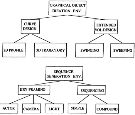
There are two major environments in our system. These are graphical object creation environment and sequence generation environment as seen in Figure 3.1. Graphical object creation environment has two subparts which are curve design and extended volume creation, and sequence generation environment also has two subparts which are key-framing and sequencing environments. There is a close relation between the key-framing and extended volume creation environments. During the key-framing phase the extended volume creation environment sup ports the creation of other transformable objects as well, like camera and light. Hence a transformable object created in this environment can be easily used in the key-framing environment as these two environments are closely related.
There is no need to switch from one environment to another because these four environments can all be active simultaneously. Hence, there is no restric tion for separating modeling and animation steps. As all environments can be active at the same time, the animator can easily go back to the object creation environment while he is dealing with sequencing, so that no work is lost because
CHAPTER 3. LOW LEVEL CONTROLS 16
Figure 3.1: Structure of the system
of things forgotten during modeling or key-framing, etc. The interactive editing facility provided in the key-framing environment supports editing key values of the parameters easily. In this manner, the system provides a flexible, extensible and modular environment in which the user can work comfortably.
3.1
The C lasses in th e M otion A b stra ctio n
System
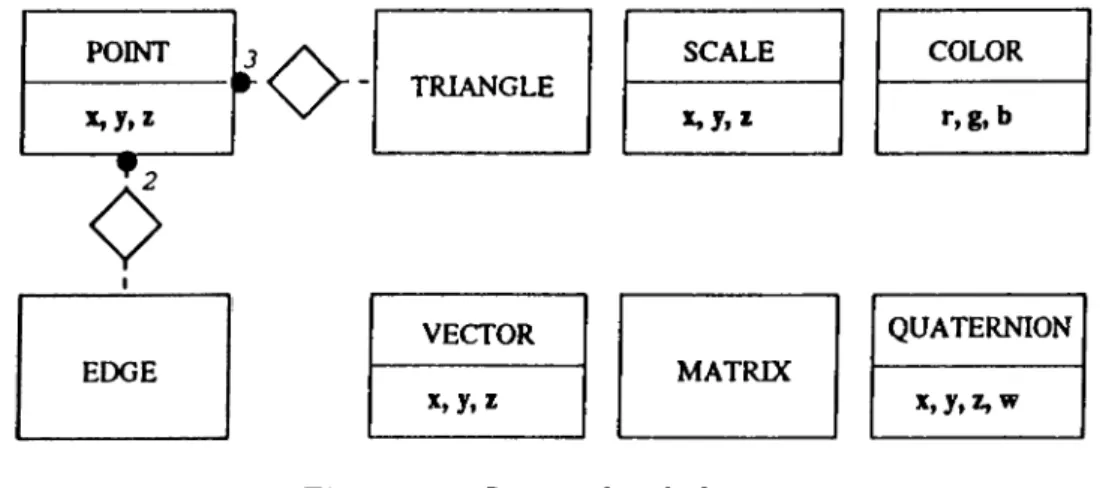
In this section the triangle sign denotes inheritance, the diamond sign denotes aggregation and the dot sign denotes multiplicity in associations. This style is taken from the Object Modeling Technique (OMT) by Rumbaugh et al [21].
CHAPTER 3. LOW LEVEL CONTROLS 17 POINT l / \ - TRIANGLE SCALE COLOR r ,g ,b VECTOR x,y,2 MATRIX QUATERNION X . y . A W
Figure 3.2: Lowest level cleisses
concepts used in any graphics subject like points, edges, vectors, etc. An edge is made up of two and a triangle is made up of three point objects. Conversion methods from a quaternion object to a matrix object and from a point object to a vector object and vice versa exist. All these classes have their own methods of their behavior on their own data. Although matrix class is implemented, it is not used for applying any transformations to any graphical object, instead quaternion is used for rotations, scale is used for scalings and point is used for translations.
Matrix objects are used in some cases for representing and concatenating trans
formations but their quaternion and point conversions are used for applying those transformations.
Generic linked lists and arrays are implemented as classes which can keep any kind of object in them and generic mesh class is implemented which keeps points, doubles or integers. The advantage of genericity is that it enables parameterized modules so that it provides re-usability in code.
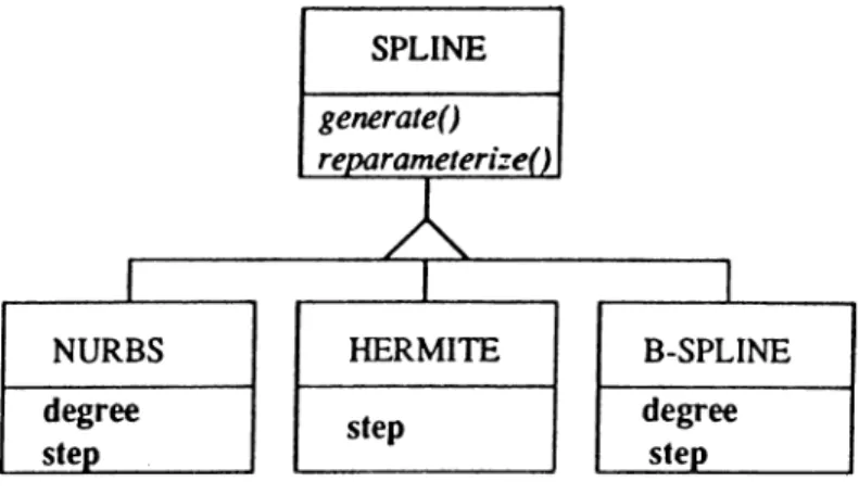
There is a spline clгıss that has three subclasses namely, nurbs, hermite and
b-spline as seen in Figure 3.3. This class provides the Hermite spline interpola
tion on the key values of the animation parameters and NURBS (Non-Uniform Rational B-Splines) approximation on the curves and meshes that the graphical objects are made of.
CHAPTER 3. LOW LEVEL CONTROLS 18
Figure 3.3: Spline class
CHAPTER 3. LOW LEVEL CONTROLS 19
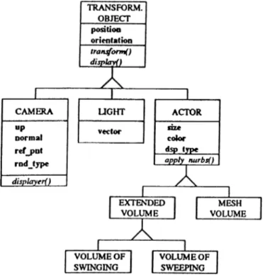
Figure 3.5: Transformable object clciss and its subclasses
There are two subclasses of curve class, Figure 3.4, which are profile and
trajectory. Curve objects are used for the creation of the extended volumes which
are volumes of swinging and volumes of sweeping. Swinging is a generalization of revolution. One profile and one trajectory curve is needed for an extended volume. Curve class has attributes like, v ertices which are arrays of points th at make up the curve and w eights which exist for each point in the vertices. These weights are used when NURBS approximation is applied onto the curve. The most im portant methods in the curve class are apply.nurhsQ, transformQ, and mapQ. The last one is for comparing two curves and generating a map for shape interpolation on curves. This shape interpolation is a base for the shape interpolation on the extended volumes explained in Section 3.3.3.
The transformable object class is one of the biggest classes in the system, and has an important role because it is the highest abstraction of the animating elements. It has the subclasses actor, camera and light as seen in Figure 3.5.
CHAPTER 3. LOW LEVEL CONTROLS 20
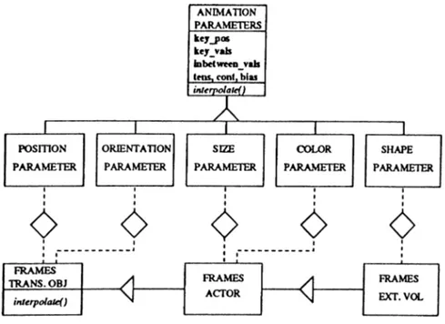
Figure 3.6: Frames and animation parameters classes
Some im portant methods in this cl£iss are transformQ and displayQ, and like almost all of the other methods of this class, these methods are virtual. Vir tual methods support overloading by run-time resolution of methods. This class has the attributes p o sitio n and o rie n ta tio n because size has no meaning for its subclasses camera and light. The subclass camera has attributes like up and n o rm a l which are vectors. Obviously, n o rm al shows the viewing direction and u p shows the inclination of the camera. The other attributes are ref_pnt, speci fying the position and rn d .ty p e , specifying the rendering type that the camera will use. The other important subclass of transformable object, actor, is the par ent class of the graphical objects. It has two subclasses, extended volume and
mesh volume and the subclass extended volume has two more subclasses, volume o f swinging and volume of sweeping. Actor class has the attributes, size, color
and dsp _ ty p e. The last one denotes the display type of the actor, which can be smoothed (NURBS applied), unsmoothed (as its control points), box (as its bounding box) or triangulated (for exporting information of a scene to external renderers like radiosity).
CHAPTER 3. LOW LEVEL CONTROLS 21
Figure 3.7: Sequence class and its subclasses
There are three levels of hierarchy in frames class as seen in Figure 3.6. The upper most class is for the transformable objects so it has the two animation parameters, position and orientation, its subclass is for iictors and has the extra animation parameters, size and color, and finally the lowest subclass is for ex tended volumes, so as the extended volumes can change shape, it has an extra
shape parameter.
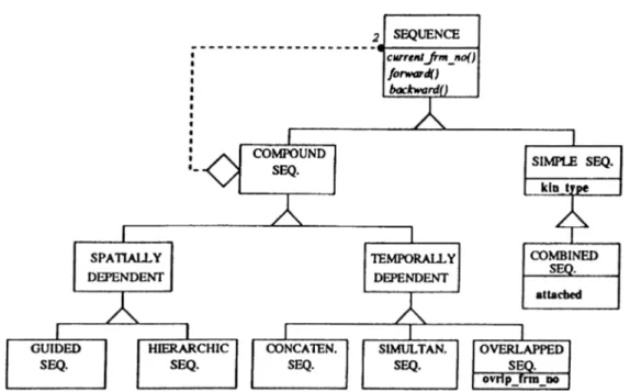
The most important class of our system is the sequence class because it is the highest abstraction of the animation sequences. As seen in Figure 3.7, the
sequence class has two major subclasses, simple sequence and compound sequence. Simple sequence has an attribute kin_type that denotes the kinetic information
type of the sequence. Simple sequence has a subclass combined sequence which has an attribute, a tta c h e d , denoting that the sequences combined will be at tached into each other providing a smooth transition. Compound sequence class has more varieties. It has two subclasses, temporally and spatially dependent sequences. A compound sequence is made of two sequences that is denoted by
CHAPTER 3. LOW LEVEL CONTROLS 22 EXTENDED has VOLUME CURVE FRAMES
o-
ANIMATION PARAMETERS SIMPLE SEQ. o TRANSFORM. OBJECT ---coatrali. ______________________________________________basj-£feceji£(.tû___________ ___________________________basj-efeujictLlû________________________ ^ _-bass^eaoaJa _, [CAMERA LIGHT BACKGROUND SEQUENCE
Figure 3.8: Relations among some of the classes
the recursive aggregation in the Figure 3.7. There are three subclasses of tempo
ral dependent sequence^ concatenated, simultaneous and overlapped sequences and
two subclasses of spatial dependent sequence, guided and hierarchic sequences. Sequences will be explained in detail in Chapter 4.
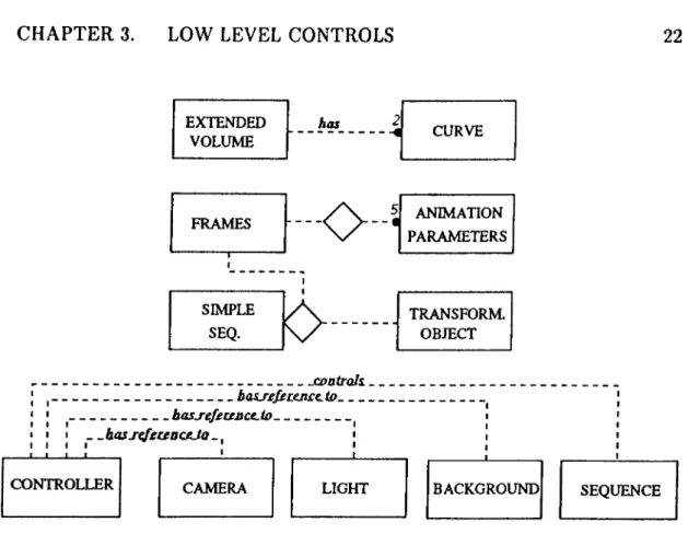
In Figure 3.8, some important associations and aggregations between some classes are presented. Aggregation is a special form of association, it is not an independent concept. If two objects are tightly bound by a part-whole relation ship then it is an aggregation but if they are considered independent even though they may be often linked then it is an association [21]. An extended volume hcis two curves, a profile and a trajectory, animation parameters are parts of a frames object, a frames object and a transformable object are parts of a simple sequence and finally, controller controls the sequences and has references to the current camera, light and background objects through the sequence.
CHAPTER 3. LOW LEVEL CONTROLS 23
3.2
Transform able O bjects
Transformable objects are actors, cameras or lights. Two kinds of light objects are designed, one is a transformable object which hcis the same properties as an actor and the other one is a point light source, again a transformable object but has no geometry. The light source which has a geometry just as an ordinary actor, is for the purpose of rendering by radiosity methods, while the other one is for the other shading techniques like constant, Gouraud and Phong shading that are provided by our system. By sending the frames to the radiosity renderer developed on the IPSC/2 Hypercube in Bilkent University, more realistically rendered images can be obtained [8]. An animation sequence rendered in this way can be seen in Figure B.5.
3.2.1 A ctors
An actor can be defined either as a network of 3D data, a mesh volume, available by some other means, such as a data file containing the 3D network data of an object, or it can be defined as a 3D volume extended from 2D, such as a volume of swinging or volume of sweeping. If preferred the 3D geometry of an aw:tor can be smoothed by fitting a NURBS on it.
There are a number of general advantages of NURBS [18] among which the following are especially useful in our application: •
• manipulation of the control points and the weights provide the ease and flexibility to design different kinds of shapes with local control,
• the evaluation of NURBS is reasonably f<ist and computationally stable, and
CHAPTER 3. LOW LEVEL CONTROLS 24
• they are invariant under affine* transformations, and perspective and par allel projections.
These are some useful properties of NURBS that become advantageous in ani mation.
The definition of a NURBS curve is as follows:
r'fu) = ^«’=0 (3.1)
where u),· are the weights, Pi are the control points and A',,p(u) are the normalized B-spline basis functions of degree p, the definition of which can be found in [18].
A NURBS surface can be defined as:
(3.2)
where Wij are the weights, Pij form a control net, and Ni,p(u) and Nj,q(v) are the normalized B-spline basis functions of degree p and q in the u and v directions respectively.
The definition of the NURBS curve can be rewritten in a simplified form as follows : C(u) = E « « ·> (“) t= 0 ^.p(«) = (3.3) (3.4) E ”=0 *"i^J.p(«)
where Ri,p(u) are rational basis functions and their analytic properties determine the geometric behavior of curves. These geometric behaviors are as follows:
some special cases of NURBS curve are Bezier and B-spline curves. *
* Affine transformations are the linear transformations such as scaling, rotation and shearing followed by a translation.
CHAPTER 3. LOW LEVEL CONTROLS 25
• a NURBS curve can be locally^ approximated, • it lies within the convex hull of the control points,
• it is invariant under affine and perspective transformations,
• it has the same differentiability properties as with the basis functions, • if a weight is set to zero, then th at control point hcis no effect on the curve, • if a weight diverges to infinity, then the curve, at the related parameter
values, converges to that point.
Extended Volume Generation
An actor may be an extended volume obtained from surfaces of swinging or surfaces of sweeping [1]. For obtaining a surface of sweeping, a profile curve must be swept through a trajectory curve, and for obtaining a surfгıce of revolution, a profile curve must be rotated around an axis of the plane it lies on. Revolution can be generalized under the word swinging. If there is a profile curve P(u) on the xj/ plane and a trajectory curve T(v) on the xz plane defined as NURBS curves as follows: F (u ) = t= 0 m T(v) = ^ T iR i„ ( v ) j - o (3.5) (3.6)
swinging the profile curve through the trajectory curve gives the following surfaw:e as seen in Figure 3.9:
5(« ,.,) = (Fx(u)r.(t,),F ,(u).F .(ti)r.(t.)) (3.7)
^Local approximation is that, if a control point or the weight of a control point is modified, this modification affects the shape of the curve only in p + 1 knot spans where p is the degree
CHAPTER 3. LOW LEVEL CONTROLS
26
Figure 3.9: A volume of swinging
Figure 3.10: A volume of sweeping
where the control points for this surfcice are
and the weights are
U7.J = WiWj
(3.8)
(3.9) Sweeping the profile curve through the trajectory curve gives the following faice as seen in Figure 3.10:
CHAPTER 3. LOW LEVEL CONTROLS 27
Figure 3.11: World and viewing coordinate systems,
where the control points for this surface are
QiJ — i,Pix d" 'I'jxi + Tjyy + Tjf) (3.11)
and the weights are obtained as in the sweeping case. Here, the P- is the rotated version of the control point Pi according to the inclinations of the trajectory curve. So both for swinging and sweeping cases, we can use a profile curve and a trajectory curve, hence swinging volumes are generated giving more flexibility than revolutions volumes.
The network of control points for extended volumes are obtained in this way and NURBS is applied over it by equation 3.2.
3 ,2 .2
C am eras
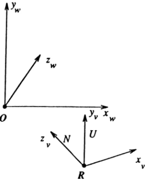
Both the world and the viewing coordinate systems are defined as left handed coordinate systems. Figure 3.11 shows the world and viewing coordinate systems according to each other. Xw, Vw, are the unit vectors on the positive x, y, z
CHAPTER 3. LOW LEVEL CONTROLS 28
axes of the world coordinate system. 0 is the origin, ((0,0,0) point) of the
world. x„, y„, are the unit vectors on the positive x, y, z axes of the viewing coordinate system. is the N (normal) and y„ is the U (up) vector of the camera. R is the reference point of the camera in world coordinates.
In order to obtain what is seen from the camera, everything defined in the world coordinate system must be redefined in the viewing coordinate system. For this purpose, the origin (O) of the world system is translated to R, then the world system is rotated to fit on the viewing system exactly. For the rotation transformation in this process, the following method as explained in [28] has been used. In this method, the transformation matrix from one coordinate system to another that has the same origin is obtained in the following way.
rpv _
f l l f l 2 ¿13 ¿21 ¿22 ¿23 ¿31 ¿32 ¿33
where T" is the transformation matrix from world coordinate system to viewing coordinate system. The i^s are as follows:
¿11 ” ¿12 ““ y w ^ v ¿13 ” ¿21 ~ ^ w V v ¿22 ~ y w V v ¿23 “ ¿31 — ¿32 = y w ^ v ¿33 = Zy,Z^,
where ¿¿xj is the dot product of the two unit vectors and gives the cosine of the angle between them. A vector p in the world coordinate system can be redefined in the viewing coordinate system as
nr*v
Pv = T^Pti (3.12)
where and are the representations of the vector p in the viewing and world coordinate systems respectively. Hence, T” is the transformation matrix that maps a vector represented in the world coordinate system to a vector represented in the viewing coordinate system. After this matrix is calculated once for a par ticular orientation of a camera, it is converted to a unit quaternion that represents
CHAPTER 3. LOW LEVEL CONTROLS 29
this rotation, and this quaternion is used for the rotation purposes. Quaternions will be explained later in detail in Section 3.3.2, and the conversions from a rotation matrix to a unit quaternion and vice versa are shown in Appendix A.
3.3
A n im ation Param eters and Their In-
b etw een in g
An animation sequence, must have a frame data where the key values for the animation parameters and their key frame numbers (times) are defined.
There are some differences on the parameters applied to the transformable objects. The parameters applicable to a camera are position and orientation parameters, and to an actor are size and color parameters as well as position and orientation ones. Position, orientation and size parameters are defined as triples
X, y, z. Color parameters are reflectivity and emission values defined as triples of /?, (7, H, where these parameters are used in rendering by radiosity.
For actors, if they are created as volumes of swinging or sweeping, then morph ing (shape change) is also possible and the shape of the actor is also a parameter of the animation.
The key values of these parameters are interpolated to generate the in-between values and resultantly, the in-between frames.
3 .3 .1 In terp olation Schem e
A very common technique used in computer animation is the key frame anima tion where the in-between frames are generated automatically based on a series of key frames supplied by the animator. If linear interpolation is used during
CHAPTER 3. LOW LEVEL CONTROLS 30
the generation of the in-between frames then undesirable side effects occur giv ing the animation a mechanical look. These problems are lack of smoothness, discontinuities in speed of motion, and distortion during rotations.
The most important advantage of an interpolation technique compared to an approximation technique is that in an interpolation scheme, the interpolated values for the parameters pass exactly through the key values, while an approxi mation scheme only approximates the key values but the approximated values do not necessarily pass through them. This property of the interpolation techniques is mostly preferred in animation because it guarantees that the the key-frames given by the animator are respected.
The best approach is to use a non-linear interpolation technique for the gener ation of the in-between values, both to avoid the problems of linear interpolation and the inadequacy of the approximation techniques.
Polynomial interpolation is the most fundamental of all interpolation concepts.
It is mostly of theoretical value because nowadays, faster and more accurate methods have been developed. These methods are piecewise polynomial methods which rely on the polynomial methods. Polynomial interpolation is not restricted to interpolation on point data; derivative data can also be interpolated. This leads to an interpolation scheme called Hermite interpolation. The piecewise polynomial scheme constructs curves that consist of polynomial pieces of the same degree and that have an overall smoothness.
piecewise cubic Hermite interpolation is one of these schemes [11]. It is a
simple interpolation technique although not the most practical one, but has some advantages for the purposes of animation. It solves the following problem:
Given some data points xo,...,XL·, their corresponding parameter values «o> · . . , and tangent vectors mo,. . . , m¿, find a C* piecewise cubic polynomial
S that interpolates to these data points, i.e, d
S{ui) = Xi
CHAPTER 3. LOW LEVEL CONTROLS 31
Over interval t € [u,, u,+i] the representation of the interpolant S in terms of the cubic Hermite polynomials h^{t) is
S{t) = Xihl(t) + m,Aj(i) + tni+ihl(t) + Xi+ihl(t) 0 < i < 1
where t is the local parameter of the interval [u,·, u,+j] [2].
The Hermite basis polynomials are defined as
(3.14) hiit) *2(0 *^(0 - 3<^ + 1 - 2Û + t = - 2i^ + 3<^ (3.15)
As the low level motion in our system is supplied by parametric key-frame interpolation method, the key values for the position, size, color and shape param eters given at the key frames are interpolated through this interpolation which provides the respection of the key values. The orientation parameter is inter polated through a special interpolation scheme for quaternions explained in the next section.
Each of the component polynomials of the animation parameters are inter polated by piecewise cubic Hermite interpolation. Two constraints are given by the interpolation conditions and other two constraints are given by specifying tangent vectors at i = 0 and < = 1. Thus Qi{t) is completely determined by the data points, and the tangent vectors at them, m,-,m,+i.
The tangent vectors at the key positions can be calculated purely from local geometry information as
— 2 i]
~ 2 ^^^'···* “ ^«) d" (^* ~ ®«-i)]
CHAPTER 3. LOW LEVEL CONTROLS 32
which is simply the average of the source chord x, — x,_i and the destination chord x,+i — X,.
A smooth animation through a given set of key values does not always pro duce the desired effect that the animator expects. Sometimes a wider, more exaggerated motion, or a motion that overshoots a key value may be desired [16]. For these purposes, adjustments on tension, bias and continuity are very helpful and generate good and challenging results for the animation. Especially, bias control easily simulates the traditional animation effects “following through af ter an action” by overshooting the key value or “exaggerating a movement” by
undershooting a key value. These adjustments are introduced to the piecewise
cubic Hermite interpolation process by means of some parameters that are used in the calculation of the resultant values of the tangent vectors that are put into the calculation of the interpolant as values m,·, m,+i, at the key positions [2]. These parameters bring the advantage of this interpolation scheme for animation purposes. They are introduced to the interpolation process by separating each tangent vector into two parts, an incoming part, from source chord and an out going part, to destination chord. The single value for tangent vector m,· in the default interpolant at each x,· is replaced by these two parts.
The complete values of tangent vectors of source chord ms,· and destination chord mdi are as follows with the use of the continuity(c), bias(b) and tension(t) parameters. ms,· = mdi = (x,· - X,_i) ( l - t , ) ( l - b c , ) ( l - 6,) (1 — ii)(l + c,)(l + hj) (®i+l (x,· X|_x) (3.17) (3.18) ( l - l i ) ( l - c i ) ( l - M
CHAPTER 3. LOW LEVEL CONTROLS 33
• ti 1, reduces the length of the tangent vector to zero and tightens the curve to a corner,
• i,· —> — 1, increases the tangent vector to twice its default length and pro duces more slack in the curve,
• t,· > 1, produces loops.
• c ,= 0, tangent continuity,
• increasing |c,| results in two tangent vectors becoming increasingly distinct, • c,· = — 1, msi reduces to the source chord, md, reduces to the destination
chord, producing a pronounced corner in the curve, • c,· —> —oo, corner more acute and curve buckles inward,
• c,· —» oo, corner pointing opposite direction.
• bi — 0, two chords are weighted equally,
• 6,· = — 1, tangent vector is determined by the destination chord,
• 6,· = 1, tangent vector is determined by the source chord,
• bi —» —oo, more the trajectory bends to one side of
• bi —» oo, more the trajectory bends to the other side of Pi,
The composite formulas, ms, and mdi provide a considerable flexibility in the construction of the resultant interpolant.
CHAPTER 3. LOW LEVEL CONTROLS 34
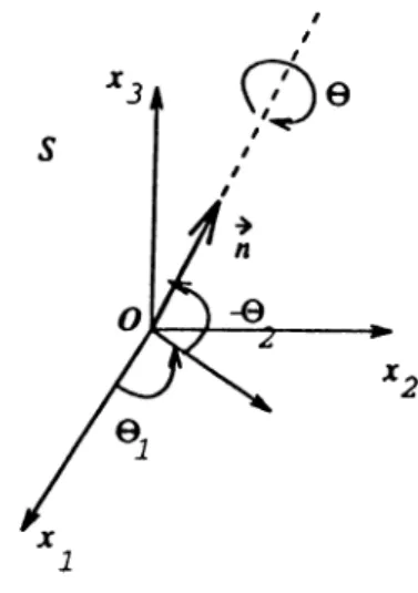
Figure 3.12: The specification of vector n
3.3.2
R e p r e se n ta tio n and In terp olation o f th e O rienta
tio n s by Q u a tern io n s
Quaternions were discovered by Sir William R. Hamilton in October, 1843, while he was trying to extend the complex plane to three dimensional space. He was trying to find a way to multiply triples so that the norm was preserved for 14 years, and finally realized th at quadruples would work. By an odd quirk of mathematics, only 2, 4 or 8 components are norm preserving as Sir Hamilton desired [23].
The common solution to the problem of representing general rotations and in-betweening them is using the Euler’s angles interpolated independently. This is not an ideal solution because the Euler angles given for rotations around dif ferent axes must be used in the given order as rotations do not commute. In stead, quaternions with interpolation on the unit sphere is better for representing and in-betweening rotations [19, 23]. Quaternions are compact and require less number of calculations for concatenating and applying rotations than the ma trix representation. An homogeneous transformation matrix in three dimensions representing a rotation is 4 x 4, hence requires 16 floating point numbers, while
CHAPTER 3. LOW LEVEL CONTROLS 35
a quaternion requires only 4 of them. Quaternions are not widely known, but conversion from Euler angles to quaternions and vice versa are well defined [23].
E u le r ’s T h eo rem : If two coordinate systems S and S have the same origin O, then the system S can be fitted on the system E by a rotation a around a line S which is the axis of rotation passing from the origin [32]. The line ex plicitly the vector that determines the line S and lies over it, can be determined by two angles (6i and $2) in the system S as seen in Figure 3.12. Therefore, the
orientation of the system E according to S can be determined by three angles, ^1, 6 2 and the amount of rotation a. These three independent angles that pro
vide the transformation from S to E are called Euler’s angles. The matrix that transforms 5” to E can be obtained by the concatenation of the rotations by these angles. In literature, different groups of Euler’s angles are used that provide this transformation. In [28], it can be found that the transformation matrix Tg that transforms E to S, is as follows for the group of 313 Euler’s angles with rotations of (ft around X3, 6 around Xi and rft around X3 again.
cos ^ cos ^ — sin ^ cos 0 sin ^ — sin V· cos ^ — cos 0008 0 sin ^ sin 0 sin 0 cos 0 sin 0 -f-sin 0 cos 0 cos 0 — sin 0 cos 0 -f cos 0 cos 0 cos 0 — sin0cos0
sin 0 sin 0 cos iftsinO cos 0
(3.19)
Again in [28], it is found that the transformation matrix can also be shown as T(n, O') = cos a l + ( 1 — cos a)nn^ -f sin a N (3.20)
where n is the unit vector that determines the axis of rotation, a is the angle of rotation as explained in Euler’s theorem, I is the identity matrix, and N is the skew symmetric matrix generated from vector n.
Therefore, these two expressions can be solved to obtain the axis and angle of rotation in terms of Euler’s angles. Instead of using the Euler’s angles in these expressions, which are very complicated, the Euler’s parameters can be used, which are much more compact [32]. Now, the axis and angle of rotation can be
CHAPTER 3. LOW LEVEL CONTROLS 36
defined in terms of four parameters called Euler’s parameters as follows.
, X = cos(a/2) (3.21)
Uj
V = V = sin (a /2) «2
.C.
. ” 3 . As the vector of rotation n is unit, then= 1 (3.22)
When 3.20 is rewritten in terms of Euler’s parameters, it is obtained that
T(u, a) = (2x^ - v ^ v )I + 2vv'^ + 2x V (3.23)
When this matrix is written explicitly and compared with the matrix in 3.19 the Euler’s parameters can be found in terms of Euler’s angles. These are
6 0 - 0 ( = ± s i n 2 C O S 2 (3.24) . 0 . 0 - 0 n = ± s m „ s i n ' 2 2 (3.25) ^ , 0 . 0 + 0 C = ± C O S 2 S i n 2 (3.26) , 0 0 + 0 ^ 2 2 (3.27)
and the signs must be taken the same for all the Euler’s parameters.
When the Euler’s parameters are used in a quadruple, it is seen that this quadruple is a quaternion and it is unit because of the relation in equation 3.22. Hence, a unit quaternion represents a rotation.
9 = V
C
X J
CHAPTER 3. LOW LEVEL CONTROLS 37
The key values for orientation which are quaternions, are interpolated by
slcrp (spherical linear interpolation) which is an interpolation scheme for quater
nions [23]. It generates in-between quaternions of two unit key quaternions by the method of great arc in-betweening on the unit sphere where unit quaternions lie.
As a brief summary of quaternions; a quaternion has four components, three of them give the axis of rotation and the fourth is obtained by the angle rotated about that axis. So, q = [s, (x, y, z ) Y is a quaternion, where the vector v = (x, is the axis of rotation and s = cos | where 0 is the angle of rotation. The multiplication of two quaternions is as follows:
[si, vi][s2, V2] = [(51S2 - v{V2), (SlUl + S2V1 -I- iTi X ^2)] (3.29)
A vector, u, can be rotated by a quaternion, q, as follows, which is shown in detail in Appendix A.
^ = Rot{v) = q[0,i^q-^ (3.30)
assuming that the vector can be represented as a quaternion of [0, w] of which the rotational part is eliminated. The inverse of a quaternion is obtained as follows
q = [S,ut 9-^ = 1 h r h f = s^ + v.v (s, -v]^ (3.31) (3.32)
The quaternion that transforms qi into q2 by analogy to the vector translation is
^ 7 = 9i” V2 (3-33)
and spherical linear interpolation in the unit quaternion space is
I
q = slerp{qi,q2,u) 0 < u < l = 9i(<7r*92)“
sin (l —u)0 sinuö = --- --- il H— r - 7Tİ2
sin 6 sin 9
(3.34) (3.35)